S.I. No. 87/2006 - European Communities (Merchant Shipping) (Ro-Ro Passenger Ship Survivability) (Amendment) Rules 2006
STATUTORY INSTRUMENTS | |||||||||||||
EUROPEAN COMMUNITIES (MERCHANT SHIPPING) (RO-RO PASSENGER SHIP SURVIVABILITY) (AMENDMENT) RULES 2006 | |||||||||||||
European Communities (Merchant Shipping) (Ro-Ro Passenger Ship Survivability) (Amendment) Rules 2006 | |||||||||||||
I, Martin Cullen, Minister for Transport, in exercise of the powers conferred on me by section 3 of the European Communities Act 1972 (No. 27 of 1972), and for the purpose of giving effect to Commission Directive 2005/12/EC of 18 February 20051 as adapted by the Maritime Transport, Safety and Security (Transfer of Departmental Administration and Ministerial Functions) Order 2005 ( S.I. No 842 of 2005 ) hereby make the following rules: | |||||||||||||
|
Citation | 1. (1) These Rules may be cited as the European Communities (Merchant Shipping) (Ro-Ro Passenger Ship Survivability) (Amendment) Rules 2006. | ||||||||||||
(2) These Rules and the Merchant Shipping Ro-Ro Passenger Ship Survivability Rules 1998 may be cited together as the Merchant Shipping (Ro-Ro Passenger Ship Survivability) Rules 1998 to 2006. | |||||||||||||
|
Interpretation | 2. In these Rules the “Principal Rules” mean the Merchant Shipping (Ro-Ro Passenger Ship Survivability) Rules 1998 ( S.I. No. 429 of 1998 ). | ||||||||||||
|
Amendment | 3. The Principal Rules are amended by: | ||||||||||||
(a) substituting for paragraph 2.3 of Annex 2 to Schedule 1 the following: | |||||||||||||
“2.3. the tightness of transverse or longitudinal bulkhead which are taken into account as effective to confine the assumed accumulated sea water in the compartment concerned in the damaged ro-ro deck shall be commensurate with the drainage system, and shall withstand hydrostatic pressure in accordance with the results of the damage calculation. Such bulkheads shall be at least 4m in height unless the height of water is less than 0.5 m. In such cases the height of the bulkhead may be calculated in accordance with the following: | |||||||||||||
Bh = 8hw | |||||||||||||
where: | |||||||||||||
Bh is the bulkhead height; | |||||||||||||
And hw is the height of water. | |||||||||||||
The minimum height shall not be less than 2.2m except in the case of a ship with hanging car decks where the minimum height of the bulkhead shall not be less than the height to the underside of the hanging deck when in its lowered position. | |||||||||||||
(b) in the Appendix entitled “MODEL TEST METHOD” | |||||||||||||
(i) by inserting “Part I” before “MODEL TEST METHOD” | |||||||||||||
(ii) by inserting “for ships tested prior to the coming into force of these rules” after “MODEL TEST METHOD” | |||||||||||||
(iii) by inserting the Schedule to these Rules after paragraph 5.2 | |||||||||||||
|
SCHEDULE | |||||||||||||
PART II | |||||||||||||
MODEL TEST METHOD FOR SHIPS TESTED ON OR AFTER THE COMING INTO FORCE OF THESE RULES | |||||||||||||
1. Objectives | |||||||||||||
This revised model test method is a revision of the method contained in the Appendix to the Annex to resolution 14 of the 1995 SOLAS Conference. Since the entry into force of the Stockholm Agreement a number of model tests has been carried out in accordance with the test method previously in force. During these tests a number of refinements in the procedures have been identified. This new model test method aims to include these refinements and, together with the Model Testing Guidance Notes attached to this Schedule, provide a more robust procedure for the assessment of survivability of a damaged ro-ro passenger ship in a seaway. In the tests provided for in paragraph 1.4. of the stability requirements pertaining to the agreement, the ship should be capable of withstanding a seaway as defined in paragraph 4 hereunder in the worst-damage-case scenario. | |||||||||||||
2. Definitions | |||||||||||||
| |||||||||||||
3. Ship model | |||||||||||||
3.1. The model should copy the actual ship for both outer configuration and internal arrangement, in particular all damaged spaces having an effect on the process of flooding and shipping of water. Intact draught, trim, heel and limiting operational KG corresponding to the worst damage case should be used. Furthermore, the test case(s) to be considered should represent the worst damage case(s) defined in accordance with SOLAS regulations II-1/8.2.3.2 (SOLAS 90) with regard to the total area under the positive GZ curve and the centreline of the damage opening should be located within the following range: | |||||||||||||
3.1.1. ± 35% LBP from midship; | |||||||||||||
3.1.2. an additional test will be required for the worst damage within ± 10% LBP from midship if the damage case referred to in .1 is outside of ± 10% LBP from midship. | |||||||||||||
3.2. The model should comply with the following: | |||||||||||||
3.2.1. length between perpendiculars (LBP) is to be at lease 3m or a length corresponding to a model scale of 1:40, whichever is greater, and the vertical extent up to at lease three superstructure standard heights above the bulkhead (freeboard) deck; | |||||||||||||
3.2.2. hull thickness of flooded spaces should not exceed 4mm; | |||||||||||||
3.2.3. in both intact and damaged conditions, the model should satisfy the correct displacement and draught marks (TA, TM, TF, port and starboard) with a maximum tolerance in any draught mark of + 2mm. Draught marks forward and aft should be located at near FP and AP as practicable; | |||||||||||||
3.2.4. all damaged compartments and ro-ro spaces should be modelled with the correct surface and volume permeabilities (actual values and distributions) ensuring that floodwater mass and mass distribution are correctly represented; | |||||||||||||
3.2.5. the characteristics of motion of the actual ship should be modelled properly, paying particular attention to the intact GM tolerance and radii of gyration in roll and pitch motion. Both radii should be measured in air and be in the range of 0.35B to 0.4B for roll motion, and 0.2LOA to 0.25LOA for pitch motion; | |||||||||||||
3.2.6. main design features such as watertight bulkheads, air escapes, etc., above and below the bulkhead deck that can result in asymmetric flooding should be modelled properly as far as practicable to represent the real situation; Ventilating and cross-flooding arrangements should be constructed to a minimum cross section of 500 mm2; | |||||||||||||
3.2.7. the shape of the damage opening should be as follows: | |||||||||||||
1. trapezoidal profile with side at 15° slope to the vertical and the width at the design waterline defined according to SOLAS regulation II-1/8.4.1; | |||||||||||||
2. isosceles triangular profile in the horizontal plane with the height equal to B/5 according to SOLAS regulation II-1/8.4.2. If side casings are fitted within B/5, the damaged length in way of the side casings should not be less than 25 mm; | |||||||||||||
3. notwithstanding the provisions of subparagraphs 3.2.7.1 and 3.2.7.2 above, all compartments taken as damaged in calculating the worst damage case(s) referred to in paragraph 3.1 should be flooded in the model tests; | |||||||||||||
3.3. The model in the flooded equilibrium condition should be heeled by an additional angle corresponding to that induced by the heeling moment Mh = max (Mpass; Mlaunch) − Mwind, but in no case should the final heel be less than 1° towards damage. Mpass; Mlaunch, and Mwind are specified in SOLAS regulation II-1/8.2.3.4. For existing ships this angle may be taken as 1°. | |||||||||||||
4. Procedures for experiments | |||||||||||||
4.1. The model should be tested in a long-crested irregular seaway defined by the JONSWAP spectrum with significant wave height HS, a peak enhancement factor Y=3.3 and a peak period TP= 4√Hs (TZ=TP/1.285). HS is the significant wave height for the area of operation, which is not exceeded by a probability of more than 10% on a yearly basis, but limited to a maximum of 4m. | |||||||||||||
Furthermore, | |||||||||||||
4.1.1. the basin width should be sufficient to avoid contact or other interaction with the sides of the basin and is recommended not to be less than LBP + 2 m; | |||||||||||||
4.1.2. the basin depth should be sufficient for proper wave modelling but should not be less than 1 m; | |||||||||||||
4.1.3. for a representative wave realisation to be used, measurements should be performed prior to the test at three different locations within the drift range; | |||||||||||||
4.1.4. the wave probe closer to the wave maker should be located at the position where the model is placed when the tests starts; | |||||||||||||
4.1.5. variation in Hs and Tp should be within ± 5% for the three locations; and | |||||||||||||
4.1.6. during the tests, for approval purposes, a tolerance of + 2.5% in Hs, ± 2.5% in Tp and ± 5% in Tz should be allowed with reference to the probe closer to the wave maker. | |||||||||||||
4.2. The model should be free to drift and placed in beam seas (90° heading) with the damage hole facing the oncoming waves, with no mooring system permanently attached to the model used. To maintain a beam sea heading of approximately 90° during the model test the following requirements should be satisfied: | |||||||||||||
4.2.1. heading control lines, intended for minor adjustment, should be located at the centre line of the stem and sterm, in a symmetrical fashion and at a level between the position of KG and the damaged waterline; and | |||||||||||||
4.2.2. the carriage speed should be equal to the actual drift speed of the model with speed adjustment made when necessary. | |||||||||||||
4.3. At least 10 experiments should be carried out. The test period for each experiment should be of a duration such that a stationary state is reached, but not less than 30 min in full-scale. A different wave realisation train should be used for each experiment. | |||||||||||||
5. Survival criteria | |||||||||||||
The model should be considered as surviving if a stationary state is reached for the successive test runs as required in paragraph 4.3. The model should be considered as capsized if angles of roll of more than 30° to the vertical axis or steady (average) heel greater than 20° for a period longer than three minutes full-scale occur, even if a stationary state is reached. | |||||||||||||
6. Test documentation | |||||||||||||
6.1. The model test programme should be approved by the Minister in advance. | |||||||||||||
6.2. Tests should be documented by means of a report and a video or other visual records containing all relevant information on the model and the test results, which are to be approved by the Minister. These should include, as a minimum, the theoretical and measured wave sprectra and statistics (Hs, Tp, TZ) of the wave elevation at the three different locations in the basin for a representative realisation, and for the tests with the model, the time series of main statistics of the measured wave elevation close to the wave maker and records of model roll, heave and pitch motions, and of the drift speed. | |||||||||||||
MODEL TEST GUIDANCE NOTES | |||||||||||||
The purpose of these guidelines is to ensure uniformity in the methods employed in the construction and verification of the model as well as in the undertaking and analyses of the model tests. | |||||||||||||
The contents of paragraphs 1 and 2 of the Appendix to Annex I are considered self-explanatory. | |||||||||||||
Paragraph 3 — Ship model | |||||||||||||
3.1 The material of which the model is made is not important in itself, provided that the model both in the intact and damaged condition is sufficiently rigid to ensure that its hydrostatic properties are the same as those of the actual ship and also that the flexural response of the hull in waves is negligible. | |||||||||||||
It is also important to ensure that the damaged compartments are modelled as accurately as practicably possible to ensure that the correct volume of flood water is represented. | |||||||||||||
Since ingress of water (even small amounts) into the intact parts of the model will affect its behaviour, measures must be taken to ensure that this ingress does not occur. | |||||||||||||
In model tests involving worst SOLAS damages near the ship ends, it has been observed that progressive flooding was not possible because of the tendency of the water on deck to accumulate near the damage opening and hence flow out. As such models were able to survive very high sea states, while they capsized in lesser sea states with less onerous SOLAS damages, away from the ends, the limit ± 35% was introduced to prevent this. | |||||||||||||
Extensive research carried out for the purpose of developing appropriate criteria for new vessels has clearly shown that in addition to the GM and freeboard being important parameters in the survivability of passenger ships, the area under the residual stability curve is also another major factor. Consequently in choosing the worst SOLAS damage for compliance with the requirement of paragraph 3.1 the worst damage is to be taken as that which gives the least area under the residual stability curve. | |||||||||||||
3.2 Model particulars | |||||||||||||
3.2.1 In recognising that scale effects play an important role in the behaviour of the model during tests, it is important to ensure that these effects are minimised as much as practically possible. The model should be as large as possible since details of damaged compartments are easier constructed in larger models and the scale effects are reduced. It is therefore required that the model length is not less than that corresponding to 1:40 scale or 3m, whichever is greater. It has been found during tests that the vertical extent of the model can affect the results when tested dynamically. It is therefore required that the ship is modelled to at least three super structure standard heights above the bulkhead (freeboard) deck so that the large waves of the wave train do not break over the model. | |||||||||||||
3.2.2 The model in way of the assumed damages must be as thin as practically possible to ensure that the amount of flood water and its centre of gravity is adequately represented. The hull thickness should not exceed 4 mm. It is recognised that it may not be possible for the model hull and the elements of primary and secondary subdivision in way of the damage to be constructed with sufficient detail and due to these constructional limitations it may not be possible to calculate accurately the assumed permeability of the space. | |||||||||||||
3.2.3 It is important that not only the draughts in the intact condition are verified, but also that the draughts of the damaged model are accurately measured for correlation with those derived from the damaged stability calculation. For practical reasons a tolerance of + 2mm in any draught is accepted. | |||||||||||||
3.2.4 After measuring the damaged draughts it may be found necessary to make adjustments to the permeability of the damaged compartment by either introducing intact volumes or by adding weights. However it is also important to ensure that the centre of gravity of the flood water is accurately represented. In this case any adjustments made must err on the side of safety. | |||||||||||||
If the model is required to be fitted with barriers on deck and the barriers are less than the bulkhead height indicated below, the model is to be fitted with CCTV so that any “splashing over” and any accumulation of water on the undamaged area of the deck can be monitored. In this case a video recording of the event is to form part of the test records. | |||||||||||||
The height of transverse or longitudinal bulkheads which are taken into account as effective to confine the assumed accumulated sea water in the compartment concerned in the damaged ro-ro deck should be at least 4m in height unless the height of water is less than 0,5 m. In such cases the height of the bulkhead may be calculated in accordance with the following: | |||||||||||||
Bh = 8hw | |||||||||||||
where Bh is the bulkhead height; and | |||||||||||||
hw is the height of water. | |||||||||||||
In any event, the minimum height of the bulkhead should be not less than 2,2 m. However, in the case of a ship with hanging car decks, the minimum height of the bulkhead should be not less than the height to the underside of the hanging car deck when in its lowered position. | |||||||||||||
3.2.5 In order to ensure that the model motion characteristics represent those of the actual ship it is important that the model is both inclined and rolled in the intact condition so that the intact GM and the mass distribution are verified. The mass distribution should be measured in air. The transverse radius of gyration of the actual ship should be in the range 0,35B to 0,4B and the longitudinal radius of gyration should be in the range 0,2L to 0,25L. | |||||||||||||
Note: While inclining and rolling the model in the damaged condition may be accepted as a check for the purpose of verifying the residual stability curve, such tests should not be accepted in lieu of the intact tests. | |||||||||||||
3.2.6 It is assumed that the ventilators of the damage compartment of the actual ship are adequate for unhindered flooding and movement of the flood water. However in trying to scale down the ventilating arrangements of the actual ship undesirable scale effects may be introduced in the model. In order to ensure that no such effects occur it is recommended to construct the ventilating arrangements to a larger scale than that of the model, ensuring that this does not affect the flow of water on the car deck. | |||||||||||||
3.2.7 It is deemed appropriate to consider a damage shape representative of a cross section of the striking ship in the bow region. The 15° angle is based on a study of the cross section at a distance of B/5 from the bow for a representative selection of vessels of different types and sizes. | |||||||||||||
The isosceles triangular profile of the prismatic damage shape is that corresponding to the load waterline. | |||||||||||||
Additionally in cases where side casings of width less than B/5 are fitted and in order to avoid any possible scale effects, the damage length in way of the side casings must not be less than 25 mm. | |||||||||||||
3.3 In the original model test method of resolution 14 of the 1995 SOLAS Conference the effect of heeling induced by the maximum moment deriving from any of passenger crowding, launching of survival craft, wind and turning was not considered even though this effect was part of SOLAS. Results from an investigation have shown, however, that it would be prudent to take these effects into account and to retain the minimum of 1° heel towards the damage for practical purposes. It is to be noted that heeling due to turning was considered not to be relevant. | |||||||||||||
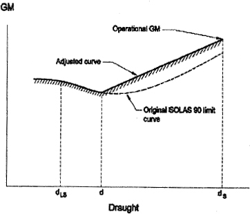
3.4 In cases where there is a margin in GM in the actual loading conditions compared to the GM limiting curve (derived from SOLAS 90), the Administration may accept that this margin is taken advantage of in the model test. In such cases the GM limiting curve should be adjusted. This adjustment can be done as follows: | |||||||||||||
| |||||||||||||
d = ds-0,6 (dS-dLS) | |||||||||||||
where: dS is the subdivision draught; and dLS is the lightship draught. | |||||||||||||
The adjusted curve is a straight line between the GM used in the model test at the subdivision draught and the intersection of the original SOLAS 90 curve and draught d. | |||||||||||||
Paragraph 4 — Procedure for experiments | |||||||||||||
4.1 Wave spectra | |||||||||||||
The JONSWAP spectrum should be used as this describes fetch- and duration-limited seas which correspond to the majority of conditions world wide. In this respect it is important that not only the peak period of the wave train is verified but also that the zero crossing period is correct. | |||||||||||||
It is required that for every test run the wave spectrum is recorded and documented. Measurements for this recording should be taken at the probe closest to the wave-making machine. | |||||||||||||
It is also required that the model is instrumented so that its motions (roll, heave and pitch) as well as its attitude (heel, sinkage and trim) are monitored and recorded through-out the test. | |||||||||||||
It has been found that it is not practical to set absolute limits for significant wave heights, peak periods and zero crossing periods of the model wave spectra. An acceptable margin has therefore been introduced. | |||||||||||||
4.2 To avoid interference of the mooring system with the ship dynamics, the towing carriage (to which the mooring system is attached) should follow the model at its actual drifting speed. In a sea state with irregular waves the drift speed will not be constant; a constant carriage speed would result in low frequency, large amplitude drift oscillations, which may affect the model behaviour. | |||||||||||||
4.3 A sufficient number of tests in different wave trains is necessary to ensure statistical reliability, i.e. the objective is to determine with a high degree of confidence that an unsafe ship will capsize in the selected conditions. A minimum number of 10 runs is considered to provide a reasonable level of reliability. | |||||||||||||
Paragraph 5 — Survival criteria | |||||||||||||
The contents of this paragraph are considered self-explanatory. | |||||||||||||
Paragraph 6 — Test approval | |||||||||||||
The following documents are to be part of the report to the administration: | |||||||||||||
(a) damage stability calculations for worst SOLAS and mid-ship damage (if different); | |||||||||||||
(b) general arrangement drawing of the model together with details of construction and instrumentation; | |||||||||||||
(c) inclining experiment and measurements of radii of gyration; | |||||||||||||
(d) nominal and measured wave spectra (at the three different locations for a representative realisation and for the tests with the model from the probe closest to the wave maker); | |||||||||||||
(e) representative record of model motions, attitude and drift; | |||||||||||||
(f) relevant video recordings. | |||||||||||||
Note: | |||||||||||||
All tests must be witnessed by the administration.’ | |||||||||||||
| |||||||||||||
|
EXPLANATORY NOTE | |||||||||||||
(This note is not part of the instrument and does not purport to be a legal interpretation) | |||||||||||||
These rules implement the provisions of Commission Directive 2005/12/EC of 18 February 2005 amending Annexes I and II to Directive 2003/25/EC of the European Parliament and of the Council on specific stability requirements for ro-ro passenger ships. | |||||||||||||