S.I. No. 98/1967 - Merchant Shipping (Passenger Ship Construction) Rules, 1967.
S.I. No. 98 of 1967. | ||||||||||||||||||||||||||||||||||||||||||||||||||||||||||||||||||||||||||||||||||||||||||||||||||||||||||||||||||||
MERCHANT SHIPPING (PASSENGER SHIP CONSTRUCTION) RULES, 1967. | ||||||||||||||||||||||||||||||||||||||||||||||||||||||||||||||||||||||||||||||||||||||||||||||||||||||||||||||||||||
ARRANGEMENT OF RULES. | ||||||||||||||||||||||||||||||||||||||||||||||||||||||||||||||||||||||||||||||||||||||||||||||||||||||||||||||||||||
PART I. | ||||||||||||||||||||||||||||||||||||||||||||||||||||||||||||||||||||||||||||||||||||||||||||||||||||||||||||||||||||
GENERAL. | ||||||||||||||||||||||||||||||||||||||||||||||||||||||||||||||||||||||||||||||||||||||||||||||||||||||||||||||||||||
Rule | ||||||||||||||||||||||||||||||||||||||||||||||||||||||||||||||||||||||||||||||||||||||||||||||||||||||||||||||||||||
2. Interpretation, application and exemption of certain ships on limited service. | ||||||||||||||||||||||||||||||||||||||||||||||||||||||||||||||||||||||||||||||||||||||||||||||||||||||||||||||||||||
PART II. | ||||||||||||||||||||||||||||||||||||||||||||||||||||||||||||||||||||||||||||||||||||||||||||||||||||||||||||||||||||
WATERTIGHT SUBDIVISION. | ||||||||||||||||||||||||||||||||||||||||||||||||||||||||||||||||||||||||||||||||||||||||||||||||||||||||||||||||||||
PART II(A). | ||||||||||||||||||||||||||||||||||||||||||||||||||||||||||||||||||||||||||||||||||||||||||||||||||||||||||||||||||||
SHIPS NOT REQUIRED TO COMPLY WITH PART II | ||||||||||||||||||||||||||||||||||||||||||||||||||||||||||||||||||||||||||||||||||||||||||||||||||||||||||||||||||||
PART III. | ||||||||||||||||||||||||||||||||||||||||||||||||||||||||||||||||||||||||||||||||||||||||||||||||||||||||||||||||||||
BILGE PUMPING ARRANGEMENTS. | ||||||||||||||||||||||||||||||||||||||||||||||||||||||||||||||||||||||||||||||||||||||||||||||||||||||||||||||||||||
Rule | ||||||||||||||||||||||||||||||||||||||||||||||||||||||||||||||||||||||||||||||||||||||||||||||||||||||||||||||||||||
27. Number and type of bilge pumps : Ships of Classes I and II. | ||||||||||||||||||||||||||||||||||||||||||||||||||||||||||||||||||||||||||||||||||||||||||||||||||||||||||||||||||||
28. Number and type of bilge pumps : Ships of Classes II(A) and III. | ||||||||||||||||||||||||||||||||||||||||||||||||||||||||||||||||||||||||||||||||||||||||||||||||||||||||||||||||||||
29. Number and type of bilge pumps, means for bailing : Ships of Classes IV to VI inclusive. | ||||||||||||||||||||||||||||||||||||||||||||||||||||||||||||||||||||||||||||||||||||||||||||||||||||||||||||||||||||
PART IV. | ||||||||||||||||||||||||||||||||||||||||||||||||||||||||||||||||||||||||||||||||||||||||||||||||||||||||||||||||||||
ELECTRICAL EQUIPMENT AND INSTALLATIONS. | ||||||||||||||||||||||||||||||||||||||||||||||||||||||||||||||||||||||||||||||||||||||||||||||||||||||||||||||||||||
39. Main generating sets : Ships of Classes I to III inclusive. | ||||||||||||||||||||||||||||||||||||||||||||||||||||||||||||||||||||||||||||||||||||||||||||||||||||||||||||||||||||
40. Emergency source of electric power : Ships of Classes I, II and II(A). | ||||||||||||||||||||||||||||||||||||||||||||||||||||||||||||||||||||||||||||||||||||||||||||||||||||||||||||||||||||
41. Emergency source of electric power : Ships of Class III. | ||||||||||||||||||||||||||||||||||||||||||||||||||||||||||||||||||||||||||||||||||||||||||||||||||||||||||||||||||||
PART V. | ||||||||||||||||||||||||||||||||||||||||||||||||||||||||||||||||||||||||||||||||||||||||||||||||||||||||||||||||||||
FIRE PROTECTION: SHIPS OF CLASSES I, II AND II(A). | ||||||||||||||||||||||||||||||||||||||||||||||||||||||||||||||||||||||||||||||||||||||||||||||||||||||||||||||||||||
54. Restriction of combustible material, etc : Methods I and III. | ||||||||||||||||||||||||||||||||||||||||||||||||||||||||||||||||||||||||||||||||||||||||||||||||||||||||||||||||||||
Rule | ||||||||||||||||||||||||||||||||||||||||||||||||||||||||||||||||||||||||||||||||||||||||||||||||||||||||||||||||||||
55. Automatic fire alarm and fire detection systems : Methods I and III. | ||||||||||||||||||||||||||||||||||||||||||||||||||||||||||||||||||||||||||||||||||||||||||||||||||||||||||||||||||||
56. Automatic sprinkler, fire alarm and fire detection systems : Method II. | ||||||||||||||||||||||||||||||||||||||||||||||||||||||||||||||||||||||||||||||||||||||||||||||||||||||||||||||||||||
58. Separation of accommodation spaces from other enclosed spaces. | ||||||||||||||||||||||||||||||||||||||||||||||||||||||||||||||||||||||||||||||||||||||||||||||||||||||||||||||||||||
59. Protection of lifts and vertical trunks for light and air. | ||||||||||||||||||||||||||||||||||||||||||||||||||||||||||||||||||||||||||||||||||||||||||||||||||||||||||||||||||||
PART V(A) | ||||||||||||||||||||||||||||||||||||||||||||||||||||||||||||||||||||||||||||||||||||||||||||||||||||||||||||||||||||
FIRE PROTECTION : SHIPS OF CLASSES I, II AND II(A). | ||||||||||||||||||||||||||||||||||||||||||||||||||||||||||||||||||||||||||||||||||||||||||||||||||||||||||||||||||||
65. Passenger ships carrying not more than 36 passengers to comply with certain Rules. | ||||||||||||||||||||||||||||||||||||||||||||||||||||||||||||||||||||||||||||||||||||||||||||||||||||||||||||||||||||
PART V(B). | ||||||||||||||||||||||||||||||||||||||||||||||||||||||||||||||||||||||||||||||||||||||||||||||||||||||||||||||||||||
FIRE PROTECTION : SHIPS OF CLASSES III TO VI INCLUSIVE. | ||||||||||||||||||||||||||||||||||||||||||||||||||||||||||||||||||||||||||||||||||||||||||||||||||||||||||||||||||||
PART VI. | ||||||||||||||||||||||||||||||||||||||||||||||||||||||||||||||||||||||||||||||||||||||||||||||||||||||||||||||||||||
BOILERS AND MACHINERY. | ||||||||||||||||||||||||||||||||||||||||||||||||||||||||||||||||||||||||||||||||||||||||||||||||||||||||||||||||||||
81. Oil fuel installations : Cooking ranges and other heating appliances. | ||||||||||||||||||||||||||||||||||||||||||||||||||||||||||||||||||||||||||||||||||||||||||||||||||||||||||||||||||||
Rule | ||||||||||||||||||||||||||||||||||||||||||||||||||||||||||||||||||||||||||||||||||||||||||||||||||||||||||||||||||||
PART VII. | ||||||||||||||||||||||||||||||||||||||||||||||||||||||||||||||||||||||||||||||||||||||||||||||||||||||||||||||||||||
MISCELLANEOUS. | ||||||||||||||||||||||||||||||||||||||||||||||||||||||||||||||||||||||||||||||||||||||||||||||||||||||||||||||||||||
FIRST SCHEDULE | ||||||||||||||||||||||||||||||||||||||||||||||||||||||||||||||||||||||||||||||||||||||||||||||||||||||||||||||||||||
Areas of Smooth Waters and Partially Smooth Waters. | ||||||||||||||||||||||||||||||||||||||||||||||||||||||||||||||||||||||||||||||||||||||||||||||||||||||||||||||||||||
SECOND SCHEDULE. | ||||||||||||||||||||||||||||||||||||||||||||||||||||||||||||||||||||||||||||||||||||||||||||||||||||||||||||||||||||
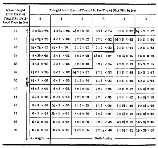
Calculation of Maximum Length of Watertight Compartments. | ||||||||||||||||||||||||||||||||||||||||||||||||||||||||||||||||||||||||||||||||||||||||||||||||||||||||||||||||||||
THIRD SCHEDULE. | ||||||||||||||||||||||||||||||||||||||||||||||||||||||||||||||||||||||||||||||||||||||||||||||||||||||||||||||||||||
Stability in damaged condition. | ||||||||||||||||||||||||||||||||||||||||||||||||||||||||||||||||||||||||||||||||||||||||||||||||||||||||||||||||||||
FOURTH SCHEDULE. | ||||||||||||||||||||||||||||||||||||||||||||||||||||||||||||||||||||||||||||||||||||||||||||||||||||||||||||||||||||
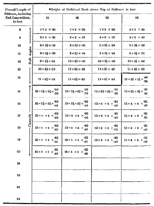
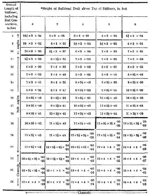
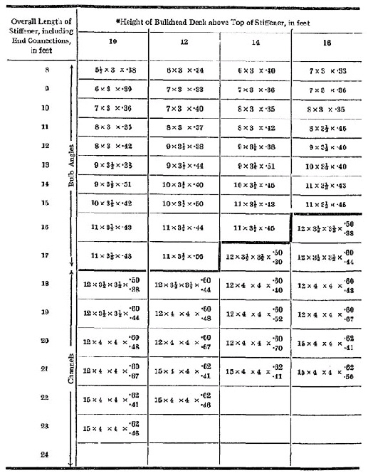
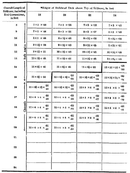
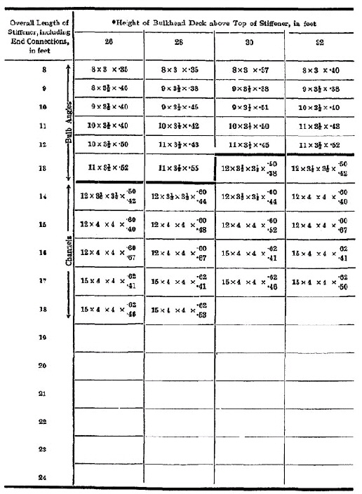
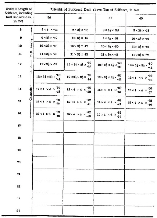
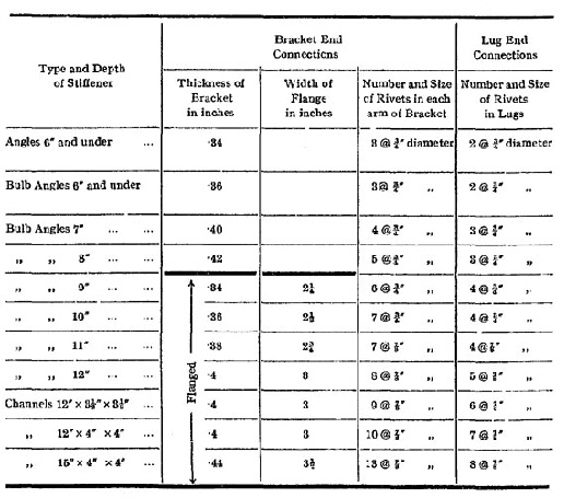
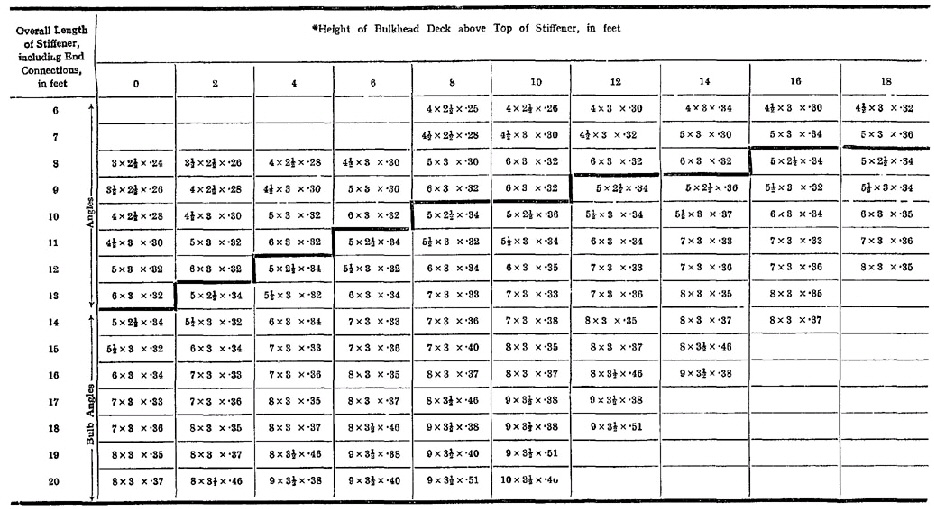
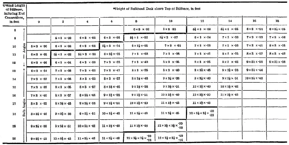
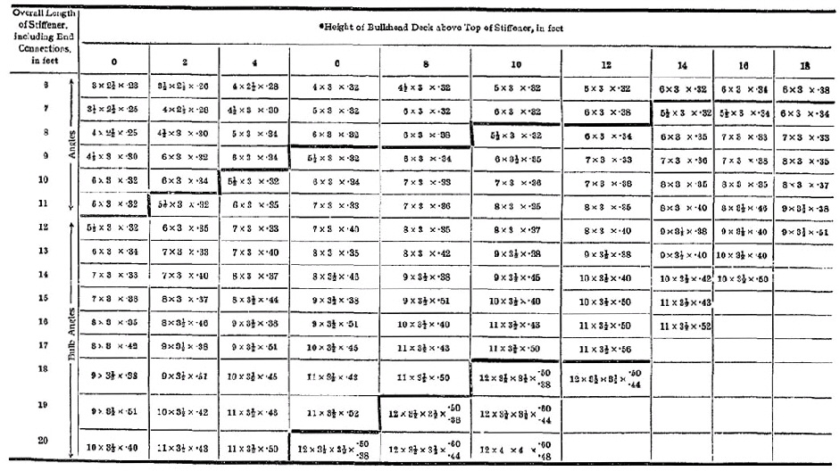
Construction of Watertight Bulkheads, etc. | ||||||||||||||||||||||||||||||||||||||||||||||||||||||||||||||||||||||||||||||||||||||||||||||||||||||||||||||||||||
FIFTH SCHEDULE. | ||||||||||||||||||||||||||||||||||||||||||||||||||||||||||||||||||||||||||||||||||||||||||||||||||||||||||||||||||||
Automatic Sprinkler, Fire Alarm, and Fire Detection system. | ||||||||||||||||||||||||||||||||||||||||||||||||||||||||||||||||||||||||||||||||||||||||||||||||||||||||||||||||||||
S.I. No. 98 of 1967. | ||||||||||||||||||||||||||||||||||||||||||||||||||||||||||||||||||||||||||||||||||||||||||||||||||||||||||||||||||||
MERCHANT SHIPPING (PASSENGER SHIP CONSTRUCTION) RULES, 1967. | ||||||||||||||||||||||||||||||||||||||||||||||||||||||||||||||||||||||||||||||||||||||||||||||||||||||||||||||||||||
I, ERSKINE H. CHILDERS, Minister for Transport and Power, in exercise of the powers conferred on me by section 10 of the Merchant Shipping (Safety Convention) Act, 1952 (No. 29 of 1952), as amended by section 9 of the Merchant Shipping Act, 1966 (No. 20 of 1966) and the Transport, Fuel and Power (Transfer of Departmental Administration and Ministerial Functions) Order, 1959 ( S.I. No. 125 of 1959 ), hereby make the following rules : | ||||||||||||||||||||||||||||||||||||||||||||||||||||||||||||||||||||||||||||||||||||||||||||||||||||||||||||||||||||
|
PART I. GENERAL. | ||||||||||||||||||||||||||||||||||||||||||||||||||||||||||||||||||||||||||||||||||||||||||||||||||||||||||||||||||||
|
1 Short title, commencement and revocation. | 1.—(1) These Rules may be cited as the Merchant Shipping (Passenger Ship Construction) Rules, 1967. | |||||||||||||||||||||||||||||||||||||||||||||||||||||||||||||||||||||||||||||||||||||||||||||||||||||||||||||||||||
(2) These Rules shall come into operation on the 14th day of May, 1967. | ||||||||||||||||||||||||||||||||||||||||||||||||||||||||||||||||||||||||||||||||||||||||||||||||||||||||||||||||||||
(3) The Merchant Shipping (Construction) Rules, 1953 ( S.I. No. 339 of 1953 ), are hereby revoked. | ||||||||||||||||||||||||||||||||||||||||||||||||||||||||||||||||||||||||||||||||||||||||||||||||||||||||||||||||||||
|
2 Interpretation, application and exemption of certain ships on limited service. | 2.—(1) In these Rules— | |||||||||||||||||||||||||||||||||||||||||||||||||||||||||||||||||||||||||||||||||||||||||||||||||||||||||||||||||||
" 'A' class division " means a bulkhead or part of a deck, in either case complying with such of the requirements of Rule 50 as are expressed to apply to "A" class divisions ; | ||||||||||||||||||||||||||||||||||||||||||||||||||||||||||||||||||||||||||||||||||||||||||||||||||||||||||||||||||||
"accommodation space" includes | ||||||||||||||||||||||||||||||||||||||||||||||||||||||||||||||||||||||||||||||||||||||||||||||||||||||||||||||||||||
(a) passenger spaces ; | ||||||||||||||||||||||||||||||||||||||||||||||||||||||||||||||||||||||||||||||||||||||||||||||||||||||||||||||||||||
(b) crew space ; | ||||||||||||||||||||||||||||||||||||||||||||||||||||||||||||||||||||||||||||||||||||||||||||||||||||||||||||||||||||
(c) offices ; | ||||||||||||||||||||||||||||||||||||||||||||||||||||||||||||||||||||||||||||||||||||||||||||||||||||||||||||||||||||
(d) pantries ; and | ||||||||||||||||||||||||||||||||||||||||||||||||||||||||||||||||||||||||||||||||||||||||||||||||||||||||||||||||||||
(e) space similar to any of the foregoing, not being service spaces or open spaces on deck ; | ||||||||||||||||||||||||||||||||||||||||||||||||||||||||||||||||||||||||||||||||||||||||||||||||||||||||||||||||||||
"auxiliary stairway" for the purpose of Rule 57(2) means a stairway of steel or other suitable material, which is not required by Rule 91 to form part of a means of escape and which serves only two decks ; | ||||||||||||||||||||||||||||||||||||||||||||||||||||||||||||||||||||||||||||||||||||||||||||||||||||||||||||||||||||
" 'B' class division" means a bulkhead complying with such of the requirements of Rule 50 as are expressed to apply to "B" class divisions ; | ||||||||||||||||||||||||||||||||||||||||||||||||||||||||||||||||||||||||||||||||||||||||||||||||||||||||||||||||||||
"breadth of the ship" means the greatest moulded breadth at or below the ship's deepest subdivision load water line ; | ||||||||||||||||||||||||||||||||||||||||||||||||||||||||||||||||||||||||||||||||||||||||||||||||||||||||||||||||||||
"bulkhead deck" means the uppermost deck up to which transverse watertight bulkheads are carried ; | ||||||||||||||||||||||||||||||||||||||||||||||||||||||||||||||||||||||||||||||||||||||||||||||||||||||||||||||||||||
"cargo space" in Part V means space appropriated for cargo, other than mail and bullion, and trunks leading to such spaces ; | ||||||||||||||||||||||||||||||||||||||||||||||||||||||||||||||||||||||||||||||||||||||||||||||||||||||||||||||||||||
"control station" includes :— | ||||||||||||||||||||||||||||||||||||||||||||||||||||||||||||||||||||||||||||||||||||||||||||||||||||||||||||||||||||
(a) a radiotelegraph room ; | ||||||||||||||||||||||||||||||||||||||||||||||||||||||||||||||||||||||||||||||||||||||||||||||||||||||||||||||||||||
(b) any other enclosed space which houses | ||||||||||||||||||||||||||||||||||||||||||||||||||||||||||||||||||||||||||||||||||||||||||||||||||||||||||||||||||||
(i) a compass, direction-finder, radar equipment, a steering wheel or other similar equipment used in navigation ; | ||||||||||||||||||||||||||||||||||||||||||||||||||||||||||||||||||||||||||||||||||||||||||||||||||||||||||||||||||||
(ii) a central indicator connected with a system for the detection of fire or smoke ; or | ||||||||||||||||||||||||||||||||||||||||||||||||||||||||||||||||||||||||||||||||||||||||||||||||||||||||||||||||||||
(iii) an emergency generator ; | ||||||||||||||||||||||||||||||||||||||||||||||||||||||||||||||||||||||||||||||||||||||||||||||||||||||||||||||||||||
"crew space" means crew accommodation within the meaning of the Merchant Shipping (Crew Accommodation on Board Ship) Regulations, 1951 ( S.I. No. 95 of 1951 ) ; | ||||||||||||||||||||||||||||||||||||||||||||||||||||||||||||||||||||||||||||||||||||||||||||||||||||||||||||||||||||
"criterion numeral" in relation to any ship means the criterion numeral of the ship determined in accordance with such of the provisions of the Second Schedule to these Rules as apply to that ship ; | ||||||||||||||||||||||||||||||||||||||||||||||||||||||||||||||||||||||||||||||||||||||||||||||||||||||||||||||||||||
"draught" means the vertical distance from the moulded base line amidships to a subdivision load water line ; | ||||||||||||||||||||||||||||||||||||||||||||||||||||||||||||||||||||||||||||||||||||||||||||||||||||||||||||||||||||
"equivalent material" where the words are used in the expression "steel or other equivalent material" means any material which, by itself or due to insulation provided, has structural and integrity properties equivalent to steel at the end of an appropriate fire test ; | ||||||||||||||||||||||||||||||||||||||||||||||||||||||||||||||||||||||||||||||||||||||||||||||||||||||||||||||||||||
"factor of subdivision" in relation to any ship or portion thereof means the factor of subdivision determined in accordance with such of the provisions of the Second Schedule to these Rules as apply to that ship or portion as the case may be ; | ||||||||||||||||||||||||||||||||||||||||||||||||||||||||||||||||||||||||||||||||||||||||||||||||||||||||||||||||||||
"floodable length" in relation to any portion of a ship at any draught means the maximum length of that portion having its centre at a given point in the ship which, at that draught and under such of the assumptions of permeability set forth in the Second Schedule to these Rules as are applicable in the circumstances, can be flooded without submerging any part of the ship's margin line when the ship has no list ; | ||||||||||||||||||||||||||||||||||||||||||||||||||||||||||||||||||||||||||||||||||||||||||||||||||||||||||||||||||||
"incombustible material" means material which when heated to a temperature of 750°C. (1382°F.) neither burns nor gives off inflammable vapours in sufficient quantity to ignite at a pilot flame nor raises the temperature of the test furnace 50°C. (90°F.) or more above 750°C. (1382°F.) when tested in accordance with a specification approved by the Minister and "combustible material" shall be construed accordingly ; | ||||||||||||||||||||||||||||||||||||||||||||||||||||||||||||||||||||||||||||||||||||||||||||||||||||||||||||||||||||
"independent power pump" means a pump operated by power otherwise than from the ship's main engines ; | ||||||||||||||||||||||||||||||||||||||||||||||||||||||||||||||||||||||||||||||||||||||||||||||||||||||||||||||||||||
"length" in relation to a ship means the length of a ship measured between perpendiculars taken at the extremities of the deepest subdivision load water line ; | ||||||||||||||||||||||||||||||||||||||||||||||||||||||||||||||||||||||||||||||||||||||||||||||||||||||||||||||||||||
"machinery space" in every Part, other than Parts V, V(A) and V(B), means any space extending from the moulded base line of the ship to the margin line and between the extreme transverse watertight bulkheads bounding the spaces containing the main and auxiliary propelling machinery, boilers serving the needs of propulsion, when installed, and the permanent coal bunkers, if any ; | ||||||||||||||||||||||||||||||||||||||||||||||||||||||||||||||||||||||||||||||||||||||||||||||||||||||||||||||||||||
"machinery space" in Parts V, V(A) and V(B) means any space used for propelling, auxiliary or refrigerating machinery, boilers, pumps, engineers' workshops, generators, ventilation or air conditioning machinery, oil filling stations and similar spaces and trunkways to such spaces ; | ||||||||||||||||||||||||||||||||||||||||||||||||||||||||||||||||||||||||||||||||||||||||||||||||||||||||||||||||||||
"main circulating pump" means the pump installed for circulating water through the main condenser ; | ||||||||||||||||||||||||||||||||||||||||||||||||||||||||||||||||||||||||||||||||||||||||||||||||||||||||||||||||||||
"main vertical zones" means the main vertical zones into which the hull, superstructure and deck houses of a ship are divided in accordance with Rule 49(1) ; | ||||||||||||||||||||||||||||||||||||||||||||||||||||||||||||||||||||||||||||||||||||||||||||||||||||||||||||||||||||
"margin line" means a line drawn at least 3 inches below the upper surface of the bulkhead deck at the side of a ship and assumed for the purpose of determining the floodable length of the ship ; | ||||||||||||||||||||||||||||||||||||||||||||||||||||||||||||||||||||||||||||||||||||||||||||||||||||||||||||||||||||
"maximum service speed" means the greatest speed which the ship is designed to maintain at sea at her deepest seagoing draught ; | ||||||||||||||||||||||||||||||||||||||||||||||||||||||||||||||||||||||||||||||||||||||||||||||||||||||||||||||||||||
"mile" means a nautical mile of 6080 feet ; | ||||||||||||||||||||||||||||||||||||||||||||||||||||||||||||||||||||||||||||||||||||||||||||||||||||||||||||||||||||
"the Minister" means the Minister for Transport and Power ; | ||||||||||||||||||||||||||||||||||||||||||||||||||||||||||||||||||||||||||||||||||||||||||||||||||||||||||||||||||||
"navigable speed" means the minimum speed at which the ship can be effectively steered in the ahead direction ; | ||||||||||||||||||||||||||||||||||||||||||||||||||||||||||||||||||||||||||||||||||||||||||||||||||||||||||||||||||||
"oil fuel unit" means the equipment used for the preparation of oil fuel for delivery to the oil burners of an oil-fired boiler and includes the oil pressure pumps, filters and heaters ; | ||||||||||||||||||||||||||||||||||||||||||||||||||||||||||||||||||||||||||||||||||||||||||||||||||||||||||||||||||||
"passenger space" means space provided for the use of passengers; | ||||||||||||||||||||||||||||||||||||||||||||||||||||||||||||||||||||||||||||||||||||||||||||||||||||||||||||||||||||
"passenger steamer" means a steamer carrying more than 12 passengers ; | ||||||||||||||||||||||||||||||||||||||||||||||||||||||||||||||||||||||||||||||||||||||||||||||||||||||||||||||||||||
"permeability" in relation to a space means the percentage of that space below the ship's margin line which, on the assumption that it is in use for the purpose for which it is appropriated, can be occupied by water ; | ||||||||||||||||||||||||||||||||||||||||||||||||||||||||||||||||||||||||||||||||||||||||||||||||||||||||||||||||||||
"permissible length" of a compartment having its centre at any point in the length of the ship means the product of the floodable length at that point and the factor of subdivision of the ship ; | ||||||||||||||||||||||||||||||||||||||||||||||||||||||||||||||||||||||||||||||||||||||||||||||||||||||||||||||||||||
"public rooms" includes halls, dining rooms, bars, smoke rooms, lounges, recreation rooms, nurseries and libraries ; | ||||||||||||||||||||||||||||||||||||||||||||||||||||||||||||||||||||||||||||||||||||||||||||||||||||||||||||||||||||
"radiotelegraph room" has the same meaning as in the Merchant Shipping (Radio) Rules, 1967 ( S.I. No. 103 of 1967 ) ; | ||||||||||||||||||||||||||||||||||||||||||||||||||||||||||||||||||||||||||||||||||||||||||||||||||||||||||||||||||||
"service space" includes galleys, main pantries, laundries, store rooms, paint rooms, baggage rooms, mail rooms, bullion rooms, carpenters' and plumbers' workshops and trunkways leading to such spaces ; | ||||||||||||||||||||||||||||||||||||||||||||||||||||||||||||||||||||||||||||||||||||||||||||||||||||||||||||||||||||
"settling tank" means an oil storage tank having a heating surface of not less than 2 square feet per ton of oil capacity ; | ||||||||||||||||||||||||||||||||||||||||||||||||||||||||||||||||||||||||||||||||||||||||||||||||||||||||||||||||||||
"standard fire test" means a test in which specimens of the relevant bulkheads or decks, having a surface area of not less than 50 square feet and a height of 8 feet, resembling as closely as possible the intended construction and including where appropriate at least one joint, are exposed in a test furnace to a series of time temperature relationships, approximately as follows :— | ||||||||||||||||||||||||||||||||||||||||||||||||||||||||||||||||||||||||||||||||||||||||||||||||||||||||||||||||||||
At the end of the first 5 minutes 538°C. (1000°F.) ; | ||||||||||||||||||||||||||||||||||||||||||||||||||||||||||||||||||||||||||||||||||||||||||||||||||||||||||||||||||||
At the end of the first 10 minutes 704°C. (1300°F.) ; | ||||||||||||||||||||||||||||||||||||||||||||||||||||||||||||||||||||||||||||||||||||||||||||||||||||||||||||||||||||
At the end of the first 30 minutes 843°C. (1550°F.) ; | ||||||||||||||||||||||||||||||||||||||||||||||||||||||||||||||||||||||||||||||||||||||||||||||||||||||||||||||||||||
At the end of the first 60 minutes 927°C. (1700°F.) ; | ||||||||||||||||||||||||||||||||||||||||||||||||||||||||||||||||||||||||||||||||||||||||||||||||||||||||||||||||||||
"steamer" includes a ship propelled by electricity or other mechanical power ; | ||||||||||||||||||||||||||||||||||||||||||||||||||||||||||||||||||||||||||||||||||||||||||||||||||||||||||||||||||||
"steering gear power unit" means | ||||||||||||||||||||||||||||||||||||||||||||||||||||||||||||||||||||||||||||||||||||||||||||||||||||||||||||||||||||
(a) in the case of electric steering gear, the electric motor and its associated electrical equipment ; or | ||||||||||||||||||||||||||||||||||||||||||||||||||||||||||||||||||||||||||||||||||||||||||||||||||||||||||||||||||||
(b) in the case of electro-hydraulic steering gear, the electric motor, its associated electrical equipment and connected pump ; or | ||||||||||||||||||||||||||||||||||||||||||||||||||||||||||||||||||||||||||||||||||||||||||||||||||||||||||||||||||||
(c) in the case of steam-hydraulic or pneumatic-hydraulic steering gear, the driving engine and connected pump ; | ||||||||||||||||||||||||||||||||||||||||||||||||||||||||||||||||||||||||||||||||||||||||||||||||||||||||||||||||||||
"subdivision load line" has the same meaning as in Section 34 of the Merchant Shipping (Safety Convention) Act, 1952 (No. 29 of 1952) ; | ||||||||||||||||||||||||||||||||||||||||||||||||||||||||||||||||||||||||||||||||||||||||||||||||||||||||||||||||||||
"subdivision load water line" means the water line assumed in determining the subdivision of the ship in accordance with these Rules ; | ||||||||||||||||||||||||||||||||||||||||||||||||||||||||||||||||||||||||||||||||||||||||||||||||||||||||||||||||||||
"suitable" in relation to material means approved by the Minister as suitable for the purpose for which it is used ; | ||||||||||||||||||||||||||||||||||||||||||||||||||||||||||||||||||||||||||||||||||||||||||||||||||||||||||||||||||||
"surface spread of flame" for the purpose of Part V, means the surface spread of flame as defined in a specification approved by the Minister; | ||||||||||||||||||||||||||||||||||||||||||||||||||||||||||||||||||||||||||||||||||||||||||||||||||||||||||||||||||||
"tons" means gross tons ; | ||||||||||||||||||||||||||||||||||||||||||||||||||||||||||||||||||||||||||||||||||||||||||||||||||||||||||||||||||||
"voyage" includes an excursion. | ||||||||||||||||||||||||||||||||||||||||||||||||||||||||||||||||||||||||||||||||||||||||||||||||||||||||||||||||||||
"watertight" in relation to a structure means capable of preventing the passage of water through the structure in any direction under a head of water up to the ship's margin line ; | ||||||||||||||||||||||||||||||||||||||||||||||||||||||||||||||||||||||||||||||||||||||||||||||||||||||||||||||||||||
"weathertight" in relation to a structure means capable of preventing the passage of sea water through the structure in ordinary sea conditions. | ||||||||||||||||||||||||||||||||||||||||||||||||||||||||||||||||||||||||||||||||||||||||||||||||||||||||||||||||||||
(2) These Rules apply to passenger steamers registered in the State, provided that the Minister may exempt any ship the keel of which was laid before the date on which these Rules come into operation, not being a ship converted on or after that date for service as a passenger steamer, from the requirements of these Rules to the extent that he is satisfied that compliance therewith is unreasonable or impracticable in the circumstances. | ||||||||||||||||||||||||||||||||||||||||||||||||||||||||||||||||||||||||||||||||||||||||||||||||||||||||||||||||||||
(3) The Minister may exempt any ship of Class II or II(A) which does not proceed more than 20 miles from the nearest land from the requirements of these Rules to the extent that he is satisfied that compliance therewith is unreasonable or impracticable by reason of the sheltered nature and conditions of the intended services of the ship. | ||||||||||||||||||||||||||||||||||||||||||||||||||||||||||||||||||||||||||||||||||||||||||||||||||||||||||||||||||||
|
3 Classification of ship. | 3.—(1) For the purposes of these Rules passenger steamers registered in the State shall be arranged in the following classes :— | |||||||||||||||||||||||||||||||||||||||||||||||||||||||||||||||||||||||||||||||||||||||||||||||||||||||||||||||||||
(a) Class I. Ships engaged on voyages (not being short international voyages) any of which are long international voyages, | ||||||||||||||||||||||||||||||||||||||||||||||||||||||||||||||||||||||||||||||||||||||||||||||||||||||||||||||||||||
(b) Class II. Ships engaged on voyages (not being long international voyages) any of which are short international voyages, | ||||||||||||||||||||||||||||||||||||||||||||||||||||||||||||||||||||||||||||||||||||||||||||||||||||||||||||||||||||
(c) Class II(A). Ships engaged on voyages of any kind other than international voyages, | ||||||||||||||||||||||||||||||||||||||||||||||||||||||||||||||||||||||||||||||||||||||||||||||||||||||||||||||||||||
(d) Class III. Ships engaged only on voyages in the course of which they are at no time more than 70 miles by sea from their point of departure and not more than 18 miles from the coast of the State, and which are at sea only in fine weather and during restricted periods, | ||||||||||||||||||||||||||||||||||||||||||||||||||||||||||||||||||||||||||||||||||||||||||||||||||||||||||||||||||||
(e) Class IV. Ships engaged only on voyages in partially smooth waters, or voyages in smooth and partially smooth waters, | ||||||||||||||||||||||||||||||||||||||||||||||||||||||||||||||||||||||||||||||||||||||||||||||||||||||||||||||||||||
(f) Class V. Ships engaged only on voyages in smooth waters, | ||||||||||||||||||||||||||||||||||||||||||||||||||||||||||||||||||||||||||||||||||||||||||||||||||||||||||||||||||||
(g) Class VI. Ships engaged only on voyages with not more than 250 passengers on board, to sea, or in smooth or in partially smooth waters, in all cases in fine weather and during restricted periods, in the course of which the ships are at no time more than 15 miles, exclusive of any smooth waters, from their point of departure nor more than 3 miles from land. | ||||||||||||||||||||||||||||||||||||||||||||||||||||||||||||||||||||||||||||||||||||||||||||||||||||||||||||||||||||
(2) In this Rule the following expressions have the following meanings respectively :— | ||||||||||||||||||||||||||||||||||||||||||||||||||||||||||||||||||||||||||||||||||||||||||||||||||||||||||||||||||||
"long international voyage" means an international voyage which is not a short international voyage within the meaning of the Merchant Shipping (Safety Convention) Act, 1952 ( S.I. No. 29 of 1952 ) ; | ||||||||||||||||||||||||||||||||||||||||||||||||||||||||||||||||||||||||||||||||||||||||||||||||||||||||||||||||||||
"partially smooth waters" means, as respects any period, weather or ship specified in the First Schedule to these Rules, the waters of any of the areas specified in the third column of that Schedule in relation to that period, weather or ship ; | ||||||||||||||||||||||||||||||||||||||||||||||||||||||||||||||||||||||||||||||||||||||||||||||||||||||||||||||||||||
"restricted period" means a period falling wholly within either of the following periods :— | ||||||||||||||||||||||||||||||||||||||||||||||||||||||||||||||||||||||||||||||||||||||||||||||||||||||||||||||||||||
(a) between the 1st day of April and the 31st day of October in any year, both dates inclusive ; or | ||||||||||||||||||||||||||||||||||||||||||||||||||||||||||||||||||||||||||||||||||||||||||||||||||||||||||||||||||||
(b) between one hour before sunrise and one hour after sunset in the case of ships fitted with navigation lights conforming with the requirements of the Collision Regulations (Ships and Seaplanes on the Water) Order, 1965 ( S.I. No. 185 of 1965 ), and between sunrise and sunset in the case of any other ships ; | ||||||||||||||||||||||||||||||||||||||||||||||||||||||||||||||||||||||||||||||||||||||||||||||||||||||||||||||||||||
"sea" does not include any partially smooth waters ; | ||||||||||||||||||||||||||||||||||||||||||||||||||||||||||||||||||||||||||||||||||||||||||||||||||||||||||||||||||||
"smooth waters" means any waters not being the sea or partially smooth waters, and in particular means waters of any of the areas specified in the second column of the First Schedule to these Rules. | ||||||||||||||||||||||||||||||||||||||||||||||||||||||||||||||||||||||||||||||||||||||||||||||||||||||||||||||||||||
|
4 Structural strength. | 4. The structural strength of every ship to which these Rules apply shall be sufficient for the service for which the ship is intended. | |||||||||||||||||||||||||||||||||||||||||||||||||||||||||||||||||||||||||||||||||||||||||||||||||||||||||||||||||||
|
PART II WATERTIGHT SUBDIVISION | ||||||||||||||||||||||||||||||||||||||||||||||||||||||||||||||||||||||||||||||||||||||||||||||||||||||||||||||||||||
|
5 Application of Part II. | 5. This Part applies to every ship to which these Rules apply, not being an open or partially decked ship of Class V or a ship of Class VI carrying less than 101 passengers. | |||||||||||||||||||||||||||||||||||||||||||||||||||||||||||||||||||||||||||||||||||||||||||||||||||||||||||||||||||
|
6 Watertight subdivision. | 6. Every ship to which this Part applies shall be subdivided by bulkheads, which shall be watertight up to the bulkhead deck, into compartments the maximum length of which shall be calculated in accordance with such of the provisions of the Second Schedule to these Rules as apply to that ship. Every other portion of the internal structure which affects the efficiency of the subdivision of the ship shall be watertight, and shall be of a design which will maintain the integrity of the subdivision. | |||||||||||||||||||||||||||||||||||||||||||||||||||||||||||||||||||||||||||||||||||||||||||||||||||||||||||||||||||
|
7 Peak and machinery space bulkheads, shaft tunnels. etc. | 7.—(1) Every ship to which this Part applies shall be provided with a collision bulkhead which shall be watertight up to the bulkhead deck and shall be fitted at a distance from the ship's forward perpendicular of not less than 5 per cent. of the length of the ship and not more than 10 feet plus 5 per cent. of such length. If the ship has a forward superstructure, the collision bulkhead shall be extended weathertight to the deck next above the bulkhead deck. The extension shall not be required to be fitted directly over the bulkhead below, provided that it is at least 5 per cent. of the length of the ship from the forward perpendicular and the part of the bulkhead deck which forms the step is made effectively weathertight. The plating and stiffeners of such extension shall be constructed in accordance with the provisions of the Fourth Schedule to these Rules as if the extension formed part of a bulkhead immediately below the bulkhead deck. | |||||||||||||||||||||||||||||||||||||||||||||||||||||||||||||||||||||||||||||||||||||||||||||||||||||||||||||||||||
(2) Every ship to which this Part applies shall be provided with a watertight afterpeak bulkhead and with watertight bulkheads dividing the space appropriated to the main and auxiliary propelling machinery, boilers, if any, and the permanent coal bunkers, if any, from other spaces. Such bulkheads shall be watertight up to the bulkhead deck, provided that the afterpeak bulkhead may be stopped below the bulkhead deck if the safety of the ship is not thereby impaired. | ||||||||||||||||||||||||||||||||||||||||||||||||||||||||||||||||||||||||||||||||||||||||||||||||||||||||||||||||||||
(3) The stern gland of every ship to which this Part applies shall be situated in a watertight shaft tunnel or other watertight space separate from the stern tube compartment and of such a volume that if the tunnel or space is flooded the margin line will not be submerged. The stern tube shall be enclosed in a watertight compartment, the volume of which shall be the smallest compatible with the proper design of the ship. | ||||||||||||||||||||||||||||||||||||||||||||||||||||||||||||||||||||||||||||||||||||||||||||||||||||||||||||||||||||
|
8 Double bottoms. | 8.—(1) Subject to the provisions of this Rule every ship of Classes I, II and II(A) shall be fitted with a watertight double bottom which shall be at least of the following extent :— | |||||||||||||||||||||||||||||||||||||||||||||||||||||||||||||||||||||||||||||||||||||||||||||||||||||||||||||||||||
(a) in ships of 165 feet but of less than 200 feet in length—from the machinery space to the collision bulkhead or as near to that bulkhead as is practicable ; | ||||||||||||||||||||||||||||||||||||||||||||||||||||||||||||||||||||||||||||||||||||||||||||||||||||||||||||||||||||
(b) in ships of 200 feet but of less than 249 feet in length—from the collision bulkhead to the afterpeak bulkhead or as near to those bulkheads as is practicable, but not necessarily in the machinery space ; | ||||||||||||||||||||||||||||||||||||||||||||||||||||||||||||||||||||||||||||||||||||||||||||||||||||||||||||||||||||
(c) in ships of 249 feet in length or over—from the collision bulkhead to the afterpeak bulkhead or as near to those bulkheads as is practicable. | ||||||||||||||||||||||||||||||||||||||||||||||||||||||||||||||||||||||||||||||||||||||||||||||||||||||||||||||||||||
(2) In case a double bottom is required by this Rule to be fitted in a ship, its moulded depth in inches measured at the centre line shall be not less than 16 inches plus | ||||||||||||||||||||||||||||||||||||||||||||||||||||||||||||||||||||||||||||||||||||||||||||||||||||||||||||||||||||
(3) Wells constructed in the double bottom for the purpose of drainage shall not be larger nor extend downwards more than is necessary for such purpose. The depth of the well shall in no case be more than the depth of the double bottom at the centre line, less 18 inches, nor shall the well extend below the horizontal plane referred to in paragraph (2): Provided that a well extending to the outer bottom may be constructed at the after end of a shaft tunnel. | ||||||||||||||||||||||||||||||||||||||||||||||||||||||||||||||||||||||||||||||||||||||||||||||||||||||||||||||||||||
(4) Wells for purposes other than drainage shall not be constructed in the double bottom. The Minister may exempt any ship from the requirements of this paragraph in respect of any well which he is satisfied will not diminish the protection given by the double bottom. | ||||||||||||||||||||||||||||||||||||||||||||||||||||||||||||||||||||||||||||||||||||||||||||||||||||||||||||||||||||
(5) Nothing in this Rule shall require a double bottom to be fitted in way of watertight compartments of moderate size used exclusively for the carriage of liquids, if the safety of the ship will not be impaired in the event of bottom or side damage by reason of the absence of a double bottom in that position. | ||||||||||||||||||||||||||||||||||||||||||||||||||||||||||||||||||||||||||||||||||||||||||||||||||||||||||||||||||||
(6) The Minister may exempt any ship of Class II or II (A) from the requirements of a double bottom in any portion of the ship which is subdivided by application of a factor of subdivision not exceeding ·5, if he is satisfied that the fitting of a double bottom in that portion of the ship would not be compatible with the design and proper working of the ship. | ||||||||||||||||||||||||||||||||||||||||||||||||||||||||||||||||||||||||||||||||||||||||||||||||||||||||||||||||||||
|
9 Stability in damaged condition. | 9.—(1) (a) Every ship to which this Part applies shall be so constructed as to provide sufficient intact stability in all service conditionsto enable the ship to withstand the final flooding of any one of the main compartments into which the ship is subdivided in accordance with the provisions of Rule 6. If two of the main compartments, being adjacent to each other, are separated by a bulkhead which is stepped under the conditions of paragraph 6 (3) (a) of the Second Schedule to these Rules, the intact stability shall be adequate to withstand the final flooding of those two adjacent main compartments. | |||||||||||||||||||||||||||||||||||||||||||||||||||||||||||||||||||||||||||||||||||||||||||||||||||||||||||||||||||
(b) Where in any such ship the factor of subdivision required under paragraph 4 or paragraph 9 of the Second Schedule to these Rules is ·50 or less but more than ·33 intact stability shall be adequate to withstand the final flooding of any two adjacent main compartments. | ||||||||||||||||||||||||||||||||||||||||||||||||||||||||||||||||||||||||||||||||||||||||||||||||||||||||||||||||||||
(c) Where in any such ship the factor of subdivision required under paragraph 4 of the Second Schedule to these Rules is ·33 or less the intact stability shall be adequate to withstand the final flooding of any three adjacent main compartments. | ||||||||||||||||||||||||||||||||||||||||||||||||||||||||||||||||||||||||||||||||||||||||||||||||||||||||||||||||||||
(2) For the purposes of this Rule the sufficiency of the intact stability of every such ship shall be determined in accordance with the provisions of the Third Schedule to these Rules. | ||||||||||||||||||||||||||||||||||||||||||||||||||||||||||||||||||||||||||||||||||||||||||||||||||||||||||||||||||||
(3) (a) Every ship to which this Part applies shall be so constructed as to keep unsymmetrical flooding when the ship is in a damaged condition at the minimum consistent with efficient arrangements. If cross-flooding fittings are provided in any such ship the fittings shall, where practicable, be self-acting but in any case where controls to cross-flooding fittings are provided, they shall be capable of being operated from an accessible position above the bulkhead deck. Such fittings together with their controls as well as the maximum heel before equalisation shall be such as will not endanger the safety of the ship. The cross-flooding fittings shall be capable of reducing the heel within 15 minutes, sufficiently to meet the requirements of sub-paragraphs (b) and (c) of paragraph 3 of the Third Schedule to these Rules. | ||||||||||||||||||||||||||||||||||||||||||||||||||||||||||||||||||||||||||||||||||||||||||||||||||||||||||||||||||||
(b) In case the margin line becomes submerged during the flooding assumed for the purposes of the calculation referred to in the Third Schedule to these Rules the construction of the ship shall be such as will enable the master of the ship to ensure— | ||||||||||||||||||||||||||||||||||||||||||||||||||||||||||||||||||||||||||||||||||||||||||||||||||||||||||||||||||||
(i) that the maximum angle of heel during any stage of such flooding will not be such as will endanger the safety of the ship, and | ||||||||||||||||||||||||||||||||||||||||||||||||||||||||||||||||||||||||||||||||||||||||||||||||||||||||||||||||||||
(ii) that the margin line will not be submerged in the final stage of flooding. | ||||||||||||||||||||||||||||||||||||||||||||||||||||||||||||||||||||||||||||||||||||||||||||||||||||||||||||||||||||
(4) (a) There shall be provided in every ship to which this Part applies a document for the use of the master of the ship containing information as to the use of any cross-flooding fittings provided in the ship. | ||||||||||||||||||||||||||||||||||||||||||||||||||||||||||||||||||||||||||||||||||||||||||||||||||||||||||||||||||||
(b) There shall be provided in every ship of Classes I, II and II(A) a document for the use of the master of the ship containing the following additional information :— | ||||||||||||||||||||||||||||||||||||||||||||||||||||||||||||||||||||||||||||||||||||||||||||||||||||||||||||||||||||
(i) information necessary for the maintenance of sufficient intact stability under service conditions to enable the ship to withstand damage to the extent referred to in the Third Schedule to these Rules ; and | ||||||||||||||||||||||||||||||||||||||||||||||||||||||||||||||||||||||||||||||||||||||||||||||||||||||||||||||||||||
(ii) information as to the conditions of stability on which the calculations of heel have been based, together with a warning that excessive heeling might result should the ship sustain damage when in a less favourable condition. | ||||||||||||||||||||||||||||||||||||||||||||||||||||||||||||||||||||||||||||||||||||||||||||||||||||||||||||||||||||
|
10 Ballasting. | 10. In case ballasting with water is necessary in any ship to which this Part applies, the water ballast shall not in general be carried in tanks intended for oil fuel. In ships in which it is not practicable to avoid putting water in oil fuel tanks, oily-water separator equipment to the satisfaction of the Minister shall be fitted, or an alternative means acceptable to the Minister shall be provided for disposing of the oily-water ballast. | |||||||||||||||||||||||||||||||||||||||||||||||||||||||||||||||||||||||||||||||||||||||||||||||||||||||||||||||||||
|
11 Construction of watertight portions of ships | 11.—(1) In every ship to which this Part applies every portion of the ship required by these Rules to be watertight shall be constructed in accordance with such of the requirements of the Fourth Schedule to these Rules as apply to it. | |||||||||||||||||||||||||||||||||||||||||||||||||||||||||||||||||||||||||||||||||||||||||||||||||||||||||||||||||||
(2) In every such ship all tanks forming part of the structure of the ship and used for the storage of oil fuel or other liquids including double bottoms, peak tanks, settling tanks and bunkers shall be of a design and construction adequate for that purpose. | ||||||||||||||||||||||||||||||||||||||||||||||||||||||||||||||||||||||||||||||||||||||||||||||||||||||||||||||||||||
|
12 Openings in watertight bulkheads and other structures. | 12.—(1) In every ship of Classes I, II and II(A) the number of openings in bulkheads and other structures required by these Rules to be watertight shall be the minimum compatible with the design and proper working of the ship. | |||||||||||||||||||||||||||||||||||||||||||||||||||||||||||||||||||||||||||||||||||||||||||||||||||||||||||||||||||
(2) So far as practicable, trunks installed in connection with ventilation, forced draught or refrigeration systems in any such ship shall not pierce such bulkheads or structures. | ||||||||||||||||||||||||||||||||||||||||||||||||||||||||||||||||||||||||||||||||||||||||||||||||||||||||||||||||||||
(3) Every tunnel above the double bottom, if any, in such a ship whether for access from the crew space to the machinery space, for piping or for any other purpose, which passes through such a bulkhead shall be watertight. The means of access to at least one end of such tunnel, if it may be used as a passage at sea, shall be through a trunkway extending watertight to a height sufficient to permit access above the margin line. The means of access to the other end of the tunnel shall be through a watertight door. No tunnel shall extend through the first subdivision bulkhead abaft the collision bulkhead. | ||||||||||||||||||||||||||||||||||||||||||||||||||||||||||||||||||||||||||||||||||||||||||||||||||||||||||||||||||||
(4) Within spaces containing the main and auxiliary propelling machinery including boilers serving the needs of propulsion and all permanent bunkers, not more than one doorway, apart from the doorways to bunkers and shaft tunnels, may be fitted in each main transverse bulkhead. In case two or more shafts are fitted, the tunnels shall be connected by an inter-communicating passage. There shall be only one doorway between the machinery space and the tunnel spacesin case one or two shafts are fitted and only two doorways in case there are more than two shafts. All such doorways shall be located so as to have their sills as high as practicable. | ||||||||||||||||||||||||||||||||||||||||||||||||||||||||||||||||||||||||||||||||||||||||||||||||||||||||||||||||||||
(5) Doorways, manholes and access openings shall not be fitted in the collision bulkhead below the margin line of any ship of Classes I, II or II(A) or in any other bulkhead which is required by these Rules to be watertight and which divides a cargo space from another cargo space or from a permanent or reserve bunker : Provided that the Minister may permit any such ship to be fitted with doorways in bulkheads dividing two between deck cargo spaces if he is satisfied that ; | ||||||||||||||||||||||||||||||||||||||||||||||||||||||||||||||||||||||||||||||||||||||||||||||||||||||||||||||||||||
(a) the doorways are necessary for the proper working of the ship, | ||||||||||||||||||||||||||||||||||||||||||||||||||||||||||||||||||||||||||||||||||||||||||||||||||||||||||||||||||||
(b) the number of such doorways in the ship is the minimum compatible with the design and proper working of the ship, and they are fitted at the highest practicable level, and | ||||||||||||||||||||||||||||||||||||||||||||||||||||||||||||||||||||||||||||||||||||||||||||||||||||||||||||||||||||
(c) the outboard vertical edges of such doorways are situated at a distance as far as practicable from the ship's shell plating and in no case less than one-fifth of the breadth of the ship such distance being measured at right angles to the centre line of the ship at the level of the deepest subdivision load water line. | ||||||||||||||||||||||||||||||||||||||||||||||||||||||||||||||||||||||||||||||||||||||||||||||||||||||||||||||||||||
(6) In every ship of Classes I, II and II(A) bulkheads outside the spaces containing machinery which are required by these Rules to be watertight shall not be pierced by openings which are capable of being closed only by portable bolted plates. | ||||||||||||||||||||||||||||||||||||||||||||||||||||||||||||||||||||||||||||||||||||||||||||||||||||||||||||||||||||
(7) In every ship of Classes III to VI, inclusive, to which this Part applies, bulkheads required by these Rules to be watertight shall not be pierced by doorways, ventilation trunks or other similar openings. | ||||||||||||||||||||||||||||||||||||||||||||||||||||||||||||||||||||||||||||||||||||||||||||||||||||||||||||||||||||
(8) (a) In every ship to which this Part applies— | ||||||||||||||||||||||||||||||||||||||||||||||||||||||||||||||||||||||||||||||||||||||||||||||||||||||||||||||||||||
(i) valves and cocks not forming part of a pipe system shall not be fitted in any bulkhead required by these Rules to be watertight ; | ||||||||||||||||||||||||||||||||||||||||||||||||||||||||||||||||||||||||||||||||||||||||||||||||||||||||||||||||||||
(ii) if any such bulkhead is pierced by pipes, scuppers, electric cables or other similar fittings, provision shall be made which will ensure that the watertightness of the bulkhead is not thereby impaired ; | ||||||||||||||||||||||||||||||||||||||||||||||||||||||||||||||||||||||||||||||||||||||||||||||||||||||||||||||||||||
(iii) lead or other heat sensitive materials shall not be used in systems which penetrate watertight subdivision bulkheads, where deterioration of such systems in the event of fire would impair the watertight integrity of the bulkheads. | ||||||||||||||||||||||||||||||||||||||||||||||||||||||||||||||||||||||||||||||||||||||||||||||||||||||||||||||||||||
(b) The collision bulkhead of a ship to which this Part applies shall not be pierced below the margin line by more than one pipe : Providedthat in case the forepeak in such a ship is divided to hold two different kinds of liquids, the collision bulkhead may be pierced below the margin line by not more than two pipes. Any pipe which pierces the collision bulkhead of such a ship shall be fitted with a screw-down valve capable of being operated from above the bulkhead deck, the valve chest being secured to the forward side of the collision bulkhead. | ||||||||||||||||||||||||||||||||||||||||||||||||||||||||||||||||||||||||||||||||||||||||||||||||||||||||||||||||||||
|
13 Means of closing openings in watertight bulkheads and other structures required to be watertight. | 13.—(1) In every ship of Classes I, II and II(A) efficient means shall be provided for closing and making watertight all openings in bulkheads and other structures required by these Rules to be watertight. | |||||||||||||||||||||||||||||||||||||||||||||||||||||||||||||||||||||||||||||||||||||||||||||||||||||||||||||||||||
(2) Every door fitted to any such opening shall be a sliding watertight door : Provided that, in any ship of Class I, or in any ship of Class II or II(A) which is not required to be subdivided in accordance with Part III of the Second Schedule to these Rules, hinged watertight doors may be fitted in the following positions :— | ||||||||||||||||||||||||||||||||||||||||||||||||||||||||||||||||||||||||||||||||||||||||||||||||||||||||||||||||||||
(a) in passenger, crew and working spaces above any deck the underside of which at its lowest point is at least 7 feet above the deepest subdivision load water line ; and | ||||||||||||||||||||||||||||||||||||||||||||||||||||||||||||||||||||||||||||||||||||||||||||||||||||||||||||||||||||
(b) in any bulkhead, not being a collision bulkhead, which divides two cargo between deck spaces. | ||||||||||||||||||||||||||||||||||||||||||||||||||||||||||||||||||||||||||||||||||||||||||||||||||||||||||||||||||||
(3) Sliding watertight doors referred to in paragraph (2) may have a horizontal or vertical motion and shall be either :— | ||||||||||||||||||||||||||||||||||||||||||||||||||||||||||||||||||||||||||||||||||||||||||||||||||||||||||||||||||||
(a) hand operated only, or | ||||||||||||||||||||||||||||||||||||||||||||||||||||||||||||||||||||||||||||||||||||||||||||||||||||||||||||||||||||
(b) power operated, when so required by these Rules, as well as hand operated. | ||||||||||||||||||||||||||||||||||||||||||||||||||||||||||||||||||||||||||||||||||||||||||||||||||||||||||||||||||||
(4) Hinged watertight doors fitted in accordance with paragraph (2) (a) shall be fitted with catches, or similar quick action closing devices, capable of being worked from each side of the bulkhead in which the door is fitted. | ||||||||||||||||||||||||||||||||||||||||||||||||||||||||||||||||||||||||||||||||||||||||||||||||||||||||||||||||||||
(5) Where sliding watertight doors are fitted in the position referred to in paragraph (2) (b) such doors shall not be fitted with remote control devices, and every watertight door which is fitted in such a position and which is accessible while the ship is at sea, shall be fitted with efficient locking arrangements. | ||||||||||||||||||||||||||||||||||||||||||||||||||||||||||||||||||||||||||||||||||||||||||||||||||||||||||||||||||||
(6) Every door required by these Rules to be watertight shall be capable of being secured by means other than bolts and of being closed by means other than gravity. | ||||||||||||||||||||||||||||||||||||||||||||||||||||||||||||||||||||||||||||||||||||||||||||||||||||||||||||||||||||
(7) In every ship of Classes I, II and II(A) watertight doors fitted in bulkheads between permanent and reserve bunkers, other than the doors referred to in Rule 14 (4) shall always be accessible. | ||||||||||||||||||||||||||||||||||||||||||||||||||||||||||||||||||||||||||||||||||||||||||||||||||||||||||||||||||||
|
14 Means of operating sliding watertight doors. | 14.—(1) If in any ship of Class I, II or II(A) which is not required to be subdivided in accordance with Part III of the Second Schedule to these Rules, any sliding watertight door fitted in a bulkhead is in a position which may require it to be opened at sea and the sill thereofbelow the deepest subdivision load water line, the following provisions shall apply :— | |||||||||||||||||||||||||||||||||||||||||||||||||||||||||||||||||||||||||||||||||||||||||||||||||||||||||||||||||||
(a) in case the number of such doors (excluding doors at entrances to shaft tunnels) exceeds five, all the doors and those at the entrances to shaft tunnels, ventilation, forced draught or similar ducts shall be power operated and shall be capable of being simultaneously closed from a single position situated on the navigating bridge ; | ||||||||||||||||||||||||||||||||||||||||||||||||||||||||||||||||||||||||||||||||||||||||||||||||||||||||||||||||||||
(b) in case the number of such doors (excluding doors at entrances to shaft tunnels) is greater than one, but does not exceed five— | ||||||||||||||||||||||||||||||||||||||||||||||||||||||||||||||||||||||||||||||||||||||||||||||||||||||||||||||||||||
(i) where the ship has no passenger spaces below the bulkhead deck—all the doors may be hand operated, | ||||||||||||||||||||||||||||||||||||||||||||||||||||||||||||||||||||||||||||||||||||||||||||||||||||||||||||||||||||
(ii) where the ship has passenger spaces below the bulkhead deck—all the doors and those at the entrances to shaft tunnels, ventilation or forced draught or similar ducts, shall be power operated and shall be capable of being simultaneously closed from a single position situated on the navigating bridge ; | ||||||||||||||||||||||||||||||||||||||||||||||||||||||||||||||||||||||||||||||||||||||||||||||||||||||||||||||||||||
(c) in any ship where there are only two such doors and they lead into or are within the space containing machinery, the Minister may permit the doors to be hand operated only. | ||||||||||||||||||||||||||||||||||||||||||||||||||||||||||||||||||||||||||||||||||||||||||||||||||||||||||||||||||||
(2) Sliding watertight doors the sills of which are above the deepest subdivision load water line and below the line specified in Rule 13 (2) (a) shall be sliding doors and may be hand operated, except in vessels to which paragraph (3) applies. | ||||||||||||||||||||||||||||||||||||||||||||||||||||||||||||||||||||||||||||||||||||||||||||||||||||||||||||||||||||
(3) In every ship of Class II or II (A) which is subdivided in accordance with Part III of the second Schedule to these Rules all sliding watertight doors shall be operated by power and shall be capable of being simultaneously closed from a single position situated on the navigating bridge : Provided that if there is only one such door in any such ship and it is in the space containing machinery, it shall not be required to be operated by power. | ||||||||||||||||||||||||||||||||||||||||||||||||||||||||||||||||||||||||||||||||||||||||||||||||||||||||||||||||||||
(4) In case in any ship of Class I, II or II (A) any sliding watertight doors which may be opened at sea for the purpose of trimming coal are fitted between bunkers in the between decks below the bulkhead deck, such doors shall be operated by power. | ||||||||||||||||||||||||||||||||||||||||||||||||||||||||||||||||||||||||||||||||||||||||||||||||||||||||||||||||||||
(5) In case in any ship of Class I, II or II (A) a trunkway, being part of a refrigeration, ventilation or forced draught system, is carried through more than one transverse watertight bulkhead and the sills of the openings of such trunkways are less than 7 feet above the deepest subdivision load water line, the sliding watertight doors at such openings shall be operated by power. | ||||||||||||||||||||||||||||||||||||||||||||||||||||||||||||||||||||||||||||||||||||||||||||||||||||||||||||||||||||
(6) (a) In case a sliding watertight door is required by these Rules to be operated by power from a single position on the navigating bridge, the power system shall be so arranged that the door can also be operated by power at the door itself. The arrangement shall be such that the door will close automatically if opened at the door itself after being closed from the single position on the navigating bridge and will be capable of being kept closed at the door itself notwithstanding that an attempt may be made to open it from such single position. Handles for controlling the power system shall be provided at both sides of the bulkhead in which the door is situated and shall be so arranged that any person passing through the doorway is able to hold both handles in the open position simultaneously without being able to set the closing mechanism in operation accidentally. | ||||||||||||||||||||||||||||||||||||||||||||||||||||||||||||||||||||||||||||||||||||||||||||||||||||||||||||||||||||
(b) Sliding watertight doors shall be capable of closing as expeditiously as possible, but the rate of closing shall not be so rapid as to be a danger to persons passing through the opening. | ||||||||||||||||||||||||||||||||||||||||||||||||||||||||||||||||||||||||||||||||||||||||||||||||||||||||||||||||||||
(7) (a) In every ship of Classes I, II and II (A) there shall be at least two independent sources of power for opening and closing all sliding watertight doors which are required by these Rules to be operated by power, and each power unit shall be sufficient to operate simultaneously all such doors in the ship. The power shall be controlled from a single position on the navigating bridge, and there shall be provided at such position suitable indicators for checking that each of the two sources of power is capable of giving the required service satisfactorily. | ||||||||||||||||||||||||||||||||||||||||||||||||||||||||||||||||||||||||||||||||||||||||||||||||||||||||||||||||||||
(b) Where the sources of power are hydraulic there shall be two pumps each of which shall be capable of closing all watertight doors in not more than 60 seconds. In addition, there shall be for the whole installation hydraulic accumulators of sufficient capacity to operate all such doors at least three times, that is to say from the open to the closed position, from the closed to the open position and from the open to the closed position. The fluid used shall be one which does not freeze at any temperature liable to be encountered by the ship during its service. | ||||||||||||||||||||||||||||||||||||||||||||||||||||||||||||||||||||||||||||||||||||||||||||||||||||||||||||||||||||
(8) In every ship of Classes I, II and II (A) every sliding watertight door which is operated by power shall be provided with efficient hand-operating gear having an all-round crank motion, or some other movement providing the same guarantee of safety, capable of being operated on each side of the door itself and at an accessible position above the bulkhead deck. | ||||||||||||||||||||||||||||||||||||||||||||||||||||||||||||||||||||||||||||||||||||||||||||||||||||||||||||||||||||
(9) In every ship of Classes I, II and II (A) if a sliding watertight door is not required to be operated by power, it shall be provided with efficient hand-operating gear having an all-round crank motion, or some other movement providing the same guarantee of safety, capable of being operated on each side of the door itself and at an accessible position above the bulkhead deck. | ||||||||||||||||||||||||||||||||||||||||||||||||||||||||||||||||||||||||||||||||||||||||||||||||||||||||||||||||||||
(10) Where hand-operating gear is fitted in accordance with paragraphs (8) and (9), the Minister may permit any sliding watertight door to be operated on one side only, if the requirements of the said paragraphs cannot be met owing to the layout of the spaces. | ||||||||||||||||||||||||||||||||||||||||||||||||||||||||||||||||||||||||||||||||||||||||||||||||||||||||||||||||||||
(11) In every ship of Classes I, II and II (A)—(a) the time necessary for the complete closure of any door by means of hand-operating gear with the vessel upright shall not exceed 90 seconds, and | ||||||||||||||||||||||||||||||||||||||||||||||||||||||||||||||||||||||||||||||||||||||||||||||||||||||||||||||||||||
(b) the hand-operating gear shall be of such a design that the doors can be closed and opened from each of the required operating positions. | ||||||||||||||||||||||||||||||||||||||||||||||||||||||||||||||||||||||||||||||||||||||||||||||||||||||||||||||||||||
(12) In every ship of Classes I, II and II (A) the hand-operating gear for operating the sliding watertight doors in the machinery space from above the bulkhead deck shall be placed outside the machinery space unless such a position is inconsistent with the efficient arrangement of the necessary gearing. | ||||||||||||||||||||||||||||||||||||||||||||||||||||||||||||||||||||||||||||||||||||||||||||||||||||||||||||||||||||
(13) In every ship of Classes I, II and II (A) the means of operation of any watertight door, whether power operated or not, shall be capable of closing the door when the ship is listed to 15 degrees either way. | ||||||||||||||||||||||||||||||||||||||||||||||||||||||||||||||||||||||||||||||||||||||||||||||||||||||||||||||||||||
|
15 Watertight doors: Signals and communications. | 15.—(1) Every sliding watertight door fitted in a ship of Class I, II or II (A) shall be connected with an indicator at each position from which the door may be closed, other than at the door itself, showing when the door is open and when it is closed. | |||||||||||||||||||||||||||||||||||||||||||||||||||||||||||||||||||||||||||||||||||||||||||||||||||||||||||||||||||
(2) There shall be provided in connection with every door mentioned in paragraph (1) which is operated by power a means of giving an audible warning signal at the door itself when the door is about to be closed. The arrangement shall be such that one movement of the operating handle at the position from which the door is about to be closed will be sufficient to sound the signal and to close the door, the signal preceding the movement of the door by an interval sufficient to allow the movement of persons and articles away from the door. The signal shall continue to sound until the door is completely closed. | ||||||||||||||||||||||||||||||||||||||||||||||||||||||||||||||||||||||||||||||||||||||||||||||||||||||||||||||||||||
(3) If any door required by these Rules to be watertight is not capable of being operated from a single position on the navigating bridge, means of communication by telegraph, telephone or any other direct means shall be provided whereby the officer of the watch may communicate with the person responsible for the closing of the door. | ||||||||||||||||||||||||||||||||||||||||||||||||||||||||||||||||||||||||||||||||||||||||||||||||||||||||||||||||||||
|
16 Construction of watertight doors. | 16.—(1) Every door required by these Rules to be watertight shall be of such design, material and construction as will maintain the integrity of the watertight bulkhead in which it is fitted. Any such door giving direct access to any space which may contain bunker coal shall, together with its frame, be made of cast or mild steel. Any such door in any other position shall, together with its frame, be made of cast or mild steel or cast iron. | |||||||||||||||||||||||||||||||||||||||||||||||||||||||||||||||||||||||||||||||||||||||||||||||||||||||||||||||||||
(2) Every sliding watertight door shall be fitted with rubbing faces of brass or similar material which may be fitted either on the door itself or on the door frame, and which, if they are less than one inch in width, shall be fitted in recesses. | ||||||||||||||||||||||||||||||||||||||||||||||||||||||||||||||||||||||||||||||||||||||||||||||||||||||||||||||||||||
(3) In case screw gear is used for operating a sliding watertight door, the screw shall work in a nut of suitable metal which is resistant to corrosion. | ||||||||||||||||||||||||||||||||||||||||||||||||||||||||||||||||||||||||||||||||||||||||||||||||||||||||||||||||||||
(4) The frame of every vertically sliding watertight door shall have no groove at the bottom thereof in which dirt may lodge. The bottom of such a frame, in case it is of skeleton form, shall be so arranged that dirt cannot lodge therein. The bottom edge of every such door shall be tapered or bevelled. | ||||||||||||||||||||||||||||||||||||||||||||||||||||||||||||||||||||||||||||||||||||||||||||||||||||||||||||||||||||
(5) Every vertically sliding watertight door which is operated by power shall be so designed and fitted that, if the power supply ceases, there shall be no danger of the door dropping. | ||||||||||||||||||||||||||||||||||||||||||||||||||||||||||||||||||||||||||||||||||||||||||||||||||||||||||||||||||||
(6) Every horizontally sliding watertight door shall be so installed as to prevent its moving if the ship rolls, and if necessary a clip or other suitable device shall be provided for that purpose. The device shall not interfere with the closing of the door when the door is required to be closed. | ||||||||||||||||||||||||||||||||||||||||||||||||||||||||||||||||||||||||||||||||||||||||||||||||||||||||||||||||||||
(7) The frame of every watertight door shall be properly fitted to the bulkhead in which the door is situated, and the jointing material between the frame and the bulkhead shall be of a type which will not deteriorate or be injured by heat. | ||||||||||||||||||||||||||||||||||||||||||||||||||||||||||||||||||||||||||||||||||||||||||||||||||||||||||||||||||||
(8) Every watertight door, being a coal-bunker door, shall be provided with screens or other devices to prevent coal from interfering with its closing. | ||||||||||||||||||||||||||||||||||||||||||||||||||||||||||||||||||||||||||||||||||||||||||||||||||||||||||||||||||||
|
17 Openings in the shell plating below the margin line. | 17.—(1) In every ship to which this Part applies the number of side scuttles, scuppers, sanitary discharges and other openings in the shell plating below the margin line shall be the minimum compatible with the design and proper working of the ship. | |||||||||||||||||||||||||||||||||||||||||||||||||||||||||||||||||||||||||||||||||||||||||||||||||||||||||||||||||||
(2) The arrangements for closing each such opening below the margin line shall be consistent with its intended purpose and shall be such as will ensure watertightness. | ||||||||||||||||||||||||||||||||||||||||||||||||||||||||||||||||||||||||||||||||||||||||||||||||||||||||||||||||||||
(3) (a) In every ship of Classes I, II and II (A) the number of side scuttles below the margin line which are capable of being opened shall be the minimum compatible with the requirements of the proper operation of the ship. | ||||||||||||||||||||||||||||||||||||||||||||||||||||||||||||||||||||||||||||||||||||||||||||||||||||||||||||||||||||
(b) In case in a between decks of a ship of Classes I, II or II (A) the sills of any side scuttles are below a line drawn parallel to the bulkhead deck at side and having its lowest point 2½ per cent. of the breadth of the ship above the deepest subdivision load water line, every side scuttle in that between decks shall be of a non-opening type. If in a between decks of such a ship all the sills of the side scuttles are above the said line, every side scuttle in that between decks shall be either of a non-opening type or incapable of being opened except by a person authorised to do so by the master of the ship. No side scuttle shall be fitted so that its sill is below the deepest subdivision load water line. | ||||||||||||||||||||||||||||||||||||||||||||||||||||||||||||||||||||||||||||||||||||||||||||||||||||||||||||||||||||
(4) In every ship of Classes III to VI, inclusive, to which this Part applies all side scuttles below the margin line shall be of a non-opening type. | ||||||||||||||||||||||||||||||||||||||||||||||||||||||||||||||||||||||||||||||||||||||||||||||||||||||||||||||||||||
(5) In every ship to which this Part applies every side scuttle below the margin line shall be fitted with an efficient hinged deadlight permanently attached so that it can be readily and effectively closed and secured watertight: Provided that abaft a point one-eighth of the length of the ship from the forward perpendicular and above a line drawn parallel to the bulkhead deck at side and having its lowest point at a height of 12 feet plus 2½ per cent. of the breadth of the ship above the ship's deepest subdivision load water line, deadlights may for the purpose of these Rules be portable in crew spaces and in passenger spaces not appropriated for the use of steerage passengers within the meaning of Part III of the Merchant Shipping Act, 1894. | ||||||||||||||||||||||||||||||||||||||||||||||||||||||||||||||||||||||||||||||||||||||||||||||||||||||||||||||||||||
(6) Side scuttles shall not be fitted below the margin line in any space in a ship to which this Part applies which is appropriated solely to the carriage of cargo or coal. In case side scuttles are fitted in spaces below the margin line which may be appropriated to the carriage either of cargo or of passengers, the side scuttles and their deadlights shall be so constructed as to be incapable of being opened except by a person authorised to do so by the master of the ship. | ||||||||||||||||||||||||||||||||||||||||||||||||||||||||||||||||||||||||||||||||||||||||||||||||||||||||||||||||||||
(7) Automatic ventilating side scuttles shall not be fitted below the margin line in the shell plating of any ship to which this Part applies. | ||||||||||||||||||||||||||||||||||||||||||||||||||||||||||||||||||||||||||||||||||||||||||||||||||||||||||||||||||||
(8) (a) In every ship to which this Part applies each inlet and discharge led through the shell plating below the margin line shall be fitted with efficient and readily accessible means for preventing the accidental admission of water into the ship. Lead or other heat sensitive materials shall not be used for pipes fitted outboard of shell valves in inlets or discharges, or in any other place where the deterioration of such pipes in the event of fire would give rise to danger of flooding. | ||||||||||||||||||||||||||||||||||||||||||||||||||||||||||||||||||||||||||||||||||||||||||||||||||||||||||||||||||||
(b) Without prejudice to the generality of subparagraph (a), each discharge led through the shell plating from spaces below the margin line, not being a discharge in connection with machinery, shall be provided with either— | ||||||||||||||||||||||||||||||||||||||||||||||||||||||||||||||||||||||||||||||||||||||||||||||||||||||||||||||||||||
(i) one automatic non-return valve fitted with a positive means by which it can always be closed from a readily accessible position above the ship's bulkhead deck and with an indicator at the position from which the valve may be closed to show whether the valve is open or closed ; or | ||||||||||||||||||||||||||||||||||||||||||||||||||||||||||||||||||||||||||||||||||||||||||||||||||||||||||||||||||||
(ii) two automatic non-return valves, the upper of which is so situated above the ship's deepest subdivision load water line as to be always accessible for examination under service conditions and is of a horizontal balanced type which is normally closed. | ||||||||||||||||||||||||||||||||||||||||||||||||||||||||||||||||||||||||||||||||||||||||||||||||||||||||||||||||||||
(c) Any valve fitted in compliance with the requirements of sub-paragraph (b) which is a geared valve, or the lower of two non-geared valves, shall be secured to the ship's shell plating. | ||||||||||||||||||||||||||||||||||||||||||||||||||||||||||||||||||||||||||||||||||||||||||||||||||||||||||||||||||||
(d) All cocks and valves attached to inlets or discharges mentioned in paragraph (8) (a). other than inlets or discharges connected withmachinery, being cocks or valves fitted below the margin line or the failure of which may affect the subdivision of the ship, shall be made of steel, bronze or other equally efficient material. | ||||||||||||||||||||||||||||||||||||||||||||||||||||||||||||||||||||||||||||||||||||||||||||||||||||||||||||||||||||
(e) Main and auxilary inlets and discharges connected with machinery shall be fitted with readily accessible cocks or valves between the pipes and the ship's shell plating or between the pipes and a fabricated box attached to the shell plating. All such cocks or valves attached to such inlets or discharges and all fittings outboard thereof shall be made of steel, bronze or other suitable ductile material. If made of steel, such cocks and valves shall be protected against corrosion. | ||||||||||||||||||||||||||||||||||||||||||||||||||||||||||||||||||||||||||||||||||||||||||||||||||||||||||||||||||||
(f) Discharge pipes led through the shell plating below the margin line of any ship of Classes I to III, inclusive, shall not be fitted in a direct line between the outboard opening and the connection with the deck, water closet or other similar fitting, but shall be arranged with bends or elbows of substantial metal other than cast iron or lead. | ||||||||||||||||||||||||||||||||||||||||||||||||||||||||||||||||||||||||||||||||||||||||||||||||||||||||||||||||||||
(g) All discharge pipes led through the shell plating below the margin line in a ship to which this Part applies and the valves relating thereto shall be protected from damage. | ||||||||||||||||||||||||||||||||||||||||||||||||||||||||||||||||||||||||||||||||||||||||||||||||||||||||||||||||||||
(h) All bolts connecting cocks, valves, discharge pipes and other similar equipment to the shell plating of a ship to which this Part applies below the margin line shall have their heads outside the shell plating, and shall be either countersunk or cupheaded. | ||||||||||||||||||||||||||||||||||||||||||||||||||||||||||||||||||||||||||||||||||||||||||||||||||||||||||||||||||||
(i) Efficient means shall be provided for the drainage of all watertight decks below the margin line in a ship to which this Part applies and any drainage pipes shall be so fitted with valves or otherwise arranged as to avoid the danger of water passing from a damaged to an undamaged compartment. | ||||||||||||||||||||||||||||||||||||||||||||||||||||||||||||||||||||||||||||||||||||||||||||||||||||||||||||||||||||
(j) The inboard opening of every ash-shoot, rubbish-shoot and other similar shoot in a ship to which this Part applies shall be fitted with an efficient watertight cover, and, if such opening is below the margin line, it shall also be fitted with an automatic non-return valve in the shoot in a readily accessible position above the ship's deepest subdivision load water line. The valve shall be of the horizontal balanced type, normally closed and provided with local means for securing it in a closed position. The requirements of this sub-paragraph shall not apply to ash ejectors and expellers the inboard openings of which are in the ship's stokehold and necessarily below the deepest subdivision load water line. Such ejectors and expellers shall be fitted with means which will prevent water entering the ship. | ||||||||||||||||||||||||||||||||||||||||||||||||||||||||||||||||||||||||||||||||||||||||||||||||||||||||||||||||||||
(k) Any gangway port, cargo port or coaling port fitted below the margin line of a ship to which this Part applies shall be of adequate strength and its lowest point shall not be below the ship's deepest subdivision load water line. | ||||||||||||||||||||||||||||||||||||||||||||||||||||||||||||||||||||||||||||||||||||||||||||||||||||||||||||||||||||
(9) The Minister may exempt any ship of Classes IV to VI, inclusive, from the requirements of paragraph (8) to the extent that he is satisfied that compliance therewith is unreasonable or imoracticable in the circumstances. | ||||||||||||||||||||||||||||||||||||||||||||||||||||||||||||||||||||||||||||||||||||||||||||||||||||||||||||||||||||
|
18 Side and other openings above the margin line. | 18.—(1) In every ship to which this Part applies side scuttles, windows, gangway ports, cargo ports, bunkering ports and other openings in the shell plating above the margin line and their means of closing shall be of efficient design and construction and of sufficient strength having regard to the spaces in which they are fitted and their positions relative to the deepest subdivision load water line and to the intended service of the ship. | |||||||||||||||||||||||||||||||||||||||||||||||||||||||||||||||||||||||||||||||||||||||||||||||||||||||||||||||||||
(2) In every ship to which this Part applies efficient inside deadlights, which can be easily closed and secured watertight, shall be provided for all side scuttles to spaces below the first deck above the bulkhead deck. | ||||||||||||||||||||||||||||||||||||||||||||||||||||||||||||||||||||||||||||||||||||||||||||||||||||||||||||||||||||
|
19 Weather deck. | 19. In every ship to which this Part applies the bulkhead deck or a deck above the bulkhead deck shall be weathertight. All openings in an exposed weathertight deck shall have coamings of adequate height and strength and shall be provided with efficient and rapid means of closing so as to make them weathertight. Freeing ports, open rails and scuppers shall be fitted as necessary for rapidly clearing the weather deck of water under all weather conditions. | |||||||||||||||||||||||||||||||||||||||||||||||||||||||||||||||||||||||||||||||||||||||||||||||||||||||||||||||||||
|
20 Partial subdivision above the margin line. | 20. In every ship to which this Part applies all reasonable and practicable measures shall be taken to limit where necessary the entry and spread of water above the bulkhead deck, which measures may include partial bulkheads or webs. Where such partial watertight bulkheads and webs are fitted on the bulkhead decks, above or in the immediate vicinity of main subdivision bulkheads, they shall have watertight shell and bulkhead deck connections so as to restrict the flow of water along the deck when the ship is heeled in a damaged condition. Where such partial watertight bulkheads do not coincide with the bulkheads below, the bulkhead deck between shall be made effectively watertight. | |||||||||||||||||||||||||||||||||||||||||||||||||||||||||||||||||||||||||||||||||||||||||||||||||||||||||||||||||||
|
21 Subdivision load lines. | 21.—(1) Every ship to which this Part applies shall be marked on its sides amidships with the subdivision load lines assigned to it by the Minister. The marks shall consist of horizontal lines one inch in breadth, and nine inches in length in the case of a ship which is a load line ship for the purposes of the Merchant Shipping (Safety and Load Line Conventions) Act, 1933 , and twelve inches in length in the case of any other ship. The marks shall be painted in white or yellow on a dark ground or in black on a light ground and shall also be cut in or centre-punched or indicated by welded bead on iron or steel ships and cut into the planking on wood ships. | |||||||||||||||||||||||||||||||||||||||||||||||||||||||||||||||||||||||||||||||||||||||||||||||||||||||||||||||||||
(2) The subdivision load lines shall be identified with the letter C, and, in the case of ships of Classes I and II, with consecutive numbers beginning from the deepest subdivision load line which shall be marked C1. In the case of ships of Classes II (A) to VI, inclusive— | ||||||||||||||||||||||||||||||||||||||||||||||||||||||||||||||||||||||||||||||||||||||||||||||||||||||||||||||||||||
(a) if there is only one subdivision load line—it shall be identified with the letter C, | ||||||||||||||||||||||||||||||||||||||||||||||||||||||||||||||||||||||||||||||||||||||||||||||||||||||||||||||||||||
(b) if there is more than one subdivision load line the subdivision load lines shall be identified with the letter C | ||||||||||||||||||||||||||||||||||||||||||||||||||||||||||||||||||||||||||||||||||||||||||||||||||||||||||||||||||||
and with consecutive letters beginning from the deepest subdivision load line, which shall be marked C. | ||||||||||||||||||||||||||||||||||||||||||||||||||||||||||||||||||||||||||||||||||||||||||||||||||||||||||||||||||||
The identifying letters and numerals shall in every case be painted and cut or centre-punched or indicated by welded bead, as the case may be, on the sides of the ship in the same manner as the lines to which they relate. | ||||||||||||||||||||||||||||||||||||||||||||||||||||||||||||||||||||||||||||||||||||||||||||||||||||||||||||||||||||
|
22 Exhibition of damage control plaus. | 22. In every ship to which this Part applies there shall be permanently exhibited, for the information of the officer in charge of the ship, plans showing clearly for each deck and hold the boundaries of the watertight compartments, the opening therein, the means of closing such openings, the position of the controls and the arrangements for the correction of any list due to flooding. In addition, booklets containing such information shall be available for the use of the officers of the ship. | |||||||||||||||||||||||||||||||||||||||||||||||||||||||||||||||||||||||||||||||||||||||||||||||||||||||||||||||||||
|
PART II (A) SHIPS NOT REQUIRED TO COMPLY WITH PART II | ||||||||||||||||||||||||||||||||||||||||||||||||||||||||||||||||||||||||||||||||||||||||||||||||||||||||||||||||||||
|
23 Application of Part II (A). | 23. This Part applies to every open or partially decked ship of Class V and to every ship of Class VI carrying less than 101 passengers. | |||||||||||||||||||||||||||||||||||||||||||||||||||||||||||||||||||||||||||||||||||||||||||||||||||||||||||||||||||
|
24 Openings in sides of ship. | 24.—(1) Efficient means shall be provided for preventing the accidental admission of water into any ship to which this Part applies through any openings in the sides of the ship. | |||||||||||||||||||||||||||||||||||||||||||||||||||||||||||||||||||||||||||||||||||||||||||||||||||||||||||||||||||
(2) Every side scuttle fitted in such a ship shall be of the non-opening type and shall be watertight and of sufficient strength having regard to its position in the ship. | ||||||||||||||||||||||||||||||||||||||||||||||||||||||||||||||||||||||||||||||||||||||||||||||||||||||||||||||||||||
|
PART III BILGE PUMPING ARRANGEMENTS | ||||||||||||||||||||||||||||||||||||||||||||||||||||||||||||||||||||||||||||||||||||||||||||||||||||||||||||||||||||
|
25 Application of Part III. | 25. This Part applies to every ship to which these Rules apply. | |||||||||||||||||||||||||||||||||||||||||||||||||||||||||||||||||||||||||||||||||||||||||||||||||||||||||||||||||||
|
26 General. | 26.—(1) Except in the case of open ships of Classes V and VI not exceeding 40 feet in length, and not proceeding on voyages to a point more than 3 miles from the starting point, every ship to which these Rules apply shall be provided with an efficient pumping plant capable of pumping from and draining any watertight compartment in the ship, other than a space permanently appropriated for the carriage of fresh water, water ballast or oil and for which other efficient means of pumping or drainage are provided, under all conditions likely to arise in practice after a casualty, whether or not the ship remains upright. Wing suctions shall be provided if necessary for that purpose. Efficient arrangements shall be provided whereby water in any watertight compartment may find its way to the suction pipes. Efficient means shall be provided for draining water from all insulated holds and water which is insulated between decks in such a ship. | |||||||||||||||||||||||||||||||||||||||||||||||||||||||||||||||||||||||||||||||||||||||||||||||||||||||||||||||||||
(2) Notwithstanding paragraph (1), the Minister may allow the provision for drainage to be omitted in a particular compartment if he is satisfied :— | ||||||||||||||||||||||||||||||||||||||||||||||||||||||||||||||||||||||||||||||||||||||||||||||||||||||||||||||||||||
(a) that having regard to the calculations made in accordance with the conditions set out in the Third Schedule to these Rules, the safety of the ship will not thereby be impaired ; and | ||||||||||||||||||||||||||||||||||||||||||||||||||||||||||||||||||||||||||||||||||||||||||||||||||||||||||||||||||||
(b) that the provision of drainage would otherwise be undesirable. | ||||||||||||||||||||||||||||||||||||||||||||||||||||||||||||||||||||||||||||||||||||||||||||||||||||||||||||||||||||
|
27 Number and type of bilge pumps : Ships of Classes I and II. | 27.—(1) Every ship of Classes I and II shall be provided with pumps connected to the bilge main in accordance with the following table : | |||||||||||||||||||||||||||||||||||||||||||||||||||||||||||||||||||||||||||||||||||||||||||||||||||||||||||||||||||
TABLE | ||||||||||||||||||||||||||||||||||||||||||||||||||||||||||||||||||||||||||||||||||||||||||||||||||||||||||||||||||||
| ||||||||||||||||||||||||||||||||||||||||||||||||||||||||||||||||||||||||||||||||||||||||||||||||||||||||||||||||||||
(2) The pumps shall be arranged as follows :— | ||||||||||||||||||||||||||||||||||||||||||||||||||||||||||||||||||||||||||||||||||||||||||||||||||||||||||||||||||||
(a) one of the pumps shall be an efficient emergency pump of a submersible type having its source of power and the necessary controls situated above the ship's bulkhead deck. Such pump and its source of power shall not be installed forward of the collision bulkhead or nearer to the side of the ship than one-fifth of the breadth of the ship measured at right angles to the centre line of the ship at the level of the deepest subdivision load line ; or | ||||||||||||||||||||||||||||||||||||||||||||||||||||||||||||||||||||||||||||||||||||||||||||||||||||||||||||||||||||
(b) the power pumps in the ship and their sources of power shall be so disposed throughout the ship's length that under any condition of flooding which the ship is required to withstand at least one such pump in an undamaged watertight compartment will be available. | ||||||||||||||||||||||||||||||||||||||||||||||||||||||||||||||||||||||||||||||||||||||||||||||||||||||||||||||||||||
|
28 Number and type of bilge pumps: Ships of Classes II (A) and III. | 28.—(1) Every ship of Classes II (A) and III shall be provided with bilge pumps in accordance with the following table : | |||||||||||||||||||||||||||||||||||||||||||||||||||||||||||||||||||||||||||||||||||||||||||||||||||||||||||||||||||
TABLE | ||||||||||||||||||||||||||||||||||||||||||||||||||||||||||||||||||||||||||||||||||||||||||||||||||||||||||||||||||||
| ||||||||||||||||||||||||||||||||||||||||||||||||||||||||||||||||||||||||||||||||||||||||||||||||||||||||||||||||||||
*The main engine pump may be replaced by one independent power pump. | ||||||||||||||||||||||||||||||||||||||||||||||||||||||||||||||||||||||||||||||||||||||||||||||||||||||||||||||||||||
‡The hand pumps specified in this column may be replaced by one independent power pump. | ||||||||||||||||||||||||||||||||||||||||||||||||||||||||||||||||||||||||||||||||||||||||||||||||||||||||||||||||||||
(2) In every ship of Classes II (A) and III being of 250 feet in length or over and in every such ship of under 250 feet in length in which a hand pump is replaced by an independent power pump, Rule 27 (2) shall apply to such a ship as it applies to ships of Classes I and II. | ||||||||||||||||||||||||||||||||||||||||||||||||||||||||||||||||||||||||||||||||||||||||||||||||||||||||||||||||||||
|
29 Number and type of bilge pumps, means for bailing: Ships of Classes IV to VI inclusive. | 29.—(1) Every ship of Class IV shall be provided with a power bilge pump, which may be worked by the ship's main engines and, in addition, a hand pump other than a hand pump of the lever type. | |||||||||||||||||||||||||||||||||||||||||||||||||||||||||||||||||||||||||||||||||||||||||||||||||||||||||||||||||||
(2) Every ship of Classes V and VI shall be provided with bilge pumps and means for bailing as follows :— | ||||||||||||||||||||||||||||||||||||||||||||||||||||||||||||||||||||||||||||||||||||||||||||||||||||||||||||||||||||
(a) every such ship exceeding 60 feet in length shall be provided with a power pump, which may be worked by the main engine and, in addition, a hand pump other than a hand pump of the lever type ; | ||||||||||||||||||||||||||||||||||||||||||||||||||||||||||||||||||||||||||||||||||||||||||||||||||||||||||||||||||||
(b) every such ship, being a decked ship not exceeding 60 feet in length, shall be provided with a hand pump other than a hand pump of the lever type ; | ||||||||||||||||||||||||||||||||||||||||||||||||||||||||||||||||||||||||||||||||||||||||||||||||||||||||||||||||||||
(c) every such ship, being a partially decked ship not exceeding 60 feet in length, shall be provided with a hand pump and, in addition, two bailers or one bailer and one bucket ; | ||||||||||||||||||||||||||||||||||||||||||||||||||||||||||||||||||||||||||||||||||||||||||||||||||||||||||||||||||||
(d) every such ship, being an open ship exceeding 40 feet in length but not exceeding 60 feet in length, shall be provided with a hand pump and, in addition, two bailers or one bailer and one bucket ; | ||||||||||||||||||||||||||||||||||||||||||||||||||||||||||||||||||||||||||||||||||||||||||||||||||||||||||||||||||||
(e) every ship of Classes V and VI, being an open ship not exceeding 40 feet in length, and proceeding beyond 3 miles from the starting point of her voyage shall be provided with a hand pump and, in addition, two bailers or one bailer and one bucket ; and | ||||||||||||||||||||||||||||||||||||||||||||||||||||||||||||||||||||||||||||||||||||||||||||||||||||||||||||||||||||
(f) every ship of Class V and VI being an open ship not exceeding 40 feet in length, and not proceeding on voyages more than 3 miles from the starting point, shall be provided with two bailers or one bailer and one bucket. | ||||||||||||||||||||||||||||||||||||||||||||||||||||||||||||||||||||||||||||||||||||||||||||||||||||||||||||||||||||
|
30 Requirements for bilge pumps and bilge suctions. | 30.—(1) Power bilge pumps fitted in any ship to which these Rules apply, shall where practicable be placed in separate watertight compartments so arranged or situated as not to be readily flooded by the same damage, and in case the ship's engines and boilers are in two or more watertight compartments the bilge pumps there available shall be distributed in such compartments as widely as possible. | |||||||||||||||||||||||||||||||||||||||||||||||||||||||||||||||||||||||||||||||||||||||||||||||||||||||||||||||||||
(2) Every bilge pump provided in a ship in compliance with these Rules shall be self-priming unless efficient means of priming are provided. Every such pump, other than a hand pump of the lever type and a pump provided for peak compartments only, shall, whether operated by hand or by power, be so arranged as to be capable of drawing water from any space required by Rule 26 to be drained. | ||||||||||||||||||||||||||||||||||||||||||||||||||||||||||||||||||||||||||||||||||||||||||||||||||||||||||||||||||||
(3) Every power bilge pump in a ship to which this Part applies shall be capable of giving a speed of water of not less than 400 feet per minute through the ship's main bilge pipe when its diameter is that determined by Rule 32 (1). Every such pump shall have a direct suction from the space in which it is situated, provided that not more than two direct suctions shall be required in any one space. Every such suction shall be of a diameter not less than that of the ship's main bilge pipe. The direct suctions in the ship's machinery space shall be arranged so that water may be pumped from each side of the space through direct suctions to independent bilge pumps. | ||||||||||||||||||||||||||||||||||||||||||||||||||||||||||||||||||||||||||||||||||||||||||||||||||||||||||||||||||||
(4) There shall be provided in the stokehold of every ship to which this Part applies, being a coal burning ship, a flexible suction hose of sufficient length to reach from a fitting on an independent power bilge pump in the ship to each side of the stokehold bilges. The hose shall be in addition to the other bilge suctions required by this Rule and shall have an internal diameter of 4 inches or ½ inch larger than that of the largest branch bilge suction required by Rule 32, whichever is the less. | ||||||||||||||||||||||||||||||||||||||||||||||||||||||||||||||||||||||||||||||||||||||||||||||||||||||||||||||||||||
(5) One of the sea water pumps circulating each main engine in a ship to which this Part applies shall be fitted with direct suction connections, which shall be provided with non-return valves, to the lowest drainage level in the ship's machinery space, or as near thereto as will satisfy the Minister. Such connections in steamships shall be of a diameter at least two-thirds of that of the ship's main sea inlet, and in motor ships of the same diameter as the pump inlet. Where in the opinion of the Minister any main circulating pump is not suitable for this purpose, a direct emergency bilge suction shall be led from the largest available independent power driven pump to the drainage level of the machinery space ; the suction shall be of the same diameter as the main inlet of the pump used. The capacity of the pump so connected shall exceed that of a required bilge pump by an amount which the Minister considers satisfactory. The open end of such suctions or the strainer, if any, attached thereto shall be accessible for clearing. If the boiler fuel may be coal and there is no watertight bulkhead between the ship's engines and boilers, a direct discharge overboard shall be fitted from at least one of the aforesaid pumps unless a by-pass is fitted to the circulating discharge thereof. The spindles of the ship's main sea inlet and of the direct suction valves shall extend well above the engine room platform. | ||||||||||||||||||||||||||||||||||||||||||||||||||||||||||||||||||||||||||||||||||||||||||||||||||||||||||||||||||||
(6) The hand bilge pumps in a ship to which this Part applies shall be workable from above the ship's bulkhead deck, if any, and shall be so arranged that the bucket and tail valve can be withdrawn for examination and overhaul under flooding conditions. | ||||||||||||||||||||||||||||||||||||||||||||||||||||||||||||||||||||||||||||||||||||||||||||||||||||||||||||||||||||
|
31 Arrangement of bilge pipes. | 31.—(1) In every ship to which these Rules apply all pipes from the pumps for draining cargo spaces or any part of the machinery space shall be distinct from pipes which may be used for filling or emptying spaces in which water or oil is carried. | |||||||||||||||||||||||||||||||||||||||||||||||||||||||||||||||||||||||||||||||||||||||||||||||||||||||||||||||||||
(2) In every ship to which this Part applies all bilge pipes used in or under coal bunkers or fuel storage tanks or in boiler or machineryspaces, including spaces in which oil-settling tanks or oil fuel pumping units are situated, shall be of steel or other suitable material. | ||||||||||||||||||||||||||||||||||||||||||||||||||||||||||||||||||||||||||||||||||||||||||||||||||||||||||||||||||||
(3) Bilge suction pipes in a ship to which this Part applies shall not be led through oil tanks unless the pipes are enclosed in an oiltight trunkway. Such pipes shall not be led through double bottom tanks. | ||||||||||||||||||||||||||||||||||||||||||||||||||||||||||||||||||||||||||||||||||||||||||||||||||||||||||||||||||||
(4) In every ship to which this Part applies all bilge pipes shall be made with flanged joints and shall be thoroughly secured in position and protected where necessary against the risk of damage. Efficient expansion joints or bends shall be provided in each line of pipe, and where a connection is made at a bulkhead or elsewhere with a lead bend the radius of each bend and the distance between the axes of the straight parts of the pipes shall be not less than three times the diameter of the pipe and the length of any bend shall be not less than eight times that diameter. | ||||||||||||||||||||||||||||||||||||||||||||||||||||||||||||||||||||||||||||||||||||||||||||||||||||||||||||||||||||
|
32 Diameter of bilge suction pipes. | 32.—(1) Subject to the provisions of paragraphs (2) and (3) in every ship of Classes I to III inclusive, and in every ship of Classes IV to VI inclusive, which is required by Rule 29 to be provided with a pump, the internal diameter of main and branch bilge suction pipes shall be determined to the nearest ¼ inch calculated according to the following formulae :— | |||||||||||||||||||||||||||||||||||||||||||||||||||||||||||||||||||||||||||||||||||||||||||||||||||||||||||||||||||
| ||||||||||||||||||||||||||||||||||||||||||||||||||||||||||||||||||||||||||||||||||||||||||||||||||||||||||||||||||||
where dm=internal diameter of the main bilge suction pipes in inches. | ||||||||||||||||||||||||||||||||||||||||||||||||||||||||||||||||||||||||||||||||||||||||||||||||||||||||||||||||||||
db=internal diameter of the branch bilge suction pipes in inches. | ||||||||||||||||||||||||||||||||||||||||||||||||||||||||||||||||||||||||||||||||||||||||||||||||||||||||||||||||||||
L=length of ship in feet. | ||||||||||||||||||||||||||||||||||||||||||||||||||||||||||||||||||||||||||||||||||||||||||||||||||||||||||||||||||||
B=breadth of ship in feet. | ||||||||||||||||||||||||||||||||||||||||||||||||||||||||||||||||||||||||||||||||||||||||||||||||||||||||||||||||||||
D=moulded depth of ship at bulkhead deck in feet. | ||||||||||||||||||||||||||||||||||||||||||||||||||||||||||||||||||||||||||||||||||||||||||||||||||||||||||||||||||||
l=length of compartment in feet. | ||||||||||||||||||||||||||||||||||||||||||||||||||||||||||||||||||||||||||||||||||||||||||||||||||||||||||||||||||||
(2) No main bilge suction pipe in any ship of Classes I to III inclusive shall be less than 2½ inches in bore, and no branch suction pipe shall be less than 2 inches or need be more than 4 inches in bore. | ||||||||||||||||||||||||||||||||||||||||||||||||||||||||||||||||||||||||||||||||||||||||||||||||||||||||||||||||||||
(3) No bilge suction pipe in any ship of Classes IV to VI inclusive, which is required by Rule 29 to be provided with a pump, shall be less than 1¼ inches in bore. | ||||||||||||||||||||||||||||||||||||||||||||||||||||||||||||||||||||||||||||||||||||||||||||||||||||||||||||||||||||
|
33 Precautions against flooding through bilge pipes. | 33.—(1) In every ship to which Part II applies the bilge and ballast pumping systems shall be so arranged as to prevent water passing from the sea or from water ballast spaces into the ship's cargo spaces or into any part of the machinery space or from one watertight compartment in the ship to another. The bilge connection to any pump which effects suction from the sea or from water ballast spaces shall be made by means of either, (a) a non-return valve, or (b) a cock which cannot be opened at the same time to the bilges and to the sea or to the bilges and the water ballast spaces. Valves in bilge distribution boxes shall be of a non-return type. An arrangement of lock-up valves or of blank flanges shall be provided to prevent any deep tank in such a ship being inadvertently run up from the sea when it contains cargo or pumped out through a bilge pipe when it contains water ballast, and instructions for the working of such arrangement shall be conspicuously displayed nearby. | |||||||||||||||||||||||||||||||||||||||||||||||||||||||||||||||||||||||||||||||||||||||||||||||||||||||||||||||||||
(2) In every ship to which Part II applies provision shall be made to prevent the flooding of any watertight compartment served by a bilge suction pipe in the event of the pipe being severed or otherwise damaged in any other watertight compartment through collision or grounding. In case any part of such a pipe is situated nearer to the side of the ship than one-fifth of the mid-ship breadth of the ship measured at the level of the deepest subdivision load water line or in any duct keel, a non-return valve shall be fitted to the pipe in the watertight compartment containing the open end of the pipe. | ||||||||||||||||||||||||||||||||||||||||||||||||||||||||||||||||||||||||||||||||||||||||||||||||||||||||||||||||||||
(3) In every ship of Classes I to III inclusive the bilge main shall not be situated nearer to the ship's side than one-fifth of the breadth of the ship measured at right angles to the centre line of the ship at the level of the deepest subdivision load water line, and where any bilge pump or its pipe connecting it to the bilge main is not so situated the arrangements shall be such that damage to the ship's side penetrating to the extent of one-fifth of the ship's breadth measured as described in this paragraph shall not put the other bilge pumping arrangements out of action. | ||||||||||||||||||||||||||||||||||||||||||||||||||||||||||||||||||||||||||||||||||||||||||||||||||||||||||||||||||||
|
34 Bilge valves, cocks, etc. | 34.—(1) In every ship to which Part II applies all distribution boxes, valves and cocks fitted in connection with the bilge pumping arrangements shall be in positions which are accessible at all times in ordinary circumstances and shall be so arranged that in the event of flooding one of the bilge pumps may operate on any watertight compartment in the ship. In case in any such ship there is only one system of pipes common to all such pumps, the necessary valves or cocks for controlling the bilge suctions shall be capable of being operated from above the ship's bulkhead deck. In case an emergency bilge pumping system is provided in addition to the main bilge pumping system it shall be independent of the main system and shall be so arranged that a pump is capable of being operated on any watertight compartment under flooding conditions ; in which case the cocks and valves necessary for the operation of the emergency system shall be capable of being operated from above the bulkhead deck : Provided that in any ship of Class II (A) or Class III of under 100 feet in length provided with a hand pump of the lever type for each watertight compartment inaccordance with Rule 28 (1), the valves and cocks on the bilge main for controlling the bilge suctions shall not be required to be capable of being operated from above the ship's bulkhead deck if they are in the same compartment as a power pump. | |||||||||||||||||||||||||||||||||||||||||||||||||||||||||||||||||||||||||||||||||||||||||||||||||||||||||||||||||||
(2) In every ship to which Part II applies every operating rod for bilge suction valves or cocks shall be led as directly as possible. Every such rod passing through a cargo or coal bunker space shall be protected against damage in such spaces. | ||||||||||||||||||||||||||||||||||||||||||||||||||||||||||||||||||||||||||||||||||||||||||||||||||||||||||||||||||||
(3) In every ship to which Part II applies every valve or cock which is required by this Rule to be operated from above the bulkhead deck shall have its control at its place of operation clearly marked to show the purpose it serves and how it may be opened and closed and shall be provided with a means to indicate when it is open and when it is closed. | ||||||||||||||||||||||||||||||||||||||||||||||||||||||||||||||||||||||||||||||||||||||||||||||||||||||||||||||||||||
|
35 Bilge mud boxes and strum boxes. | 35. Bilge suctions in the machinery space of every ship to which these Rules apply shall be led from readily accessible mud boxes placed wherever practicable above the level of the working floor of such space. The boxes shall have straight tailpipes to the bilges and covers secured in such a manner as will permit them to be readily opened and closed. The suction ends in hold spaces and tunnel wells shall be enclosed in strum boxes having perforations approximately 3/8 inch in diameter, and the combined area of such perforations shall be not less than twice that of the end of the suction pipe. Strum boxes shall be so constructed that they can be cleared without breaking any joint of the suction pipe. | |||||||||||||||||||||||||||||||||||||||||||||||||||||||||||||||||||||||||||||||||||||||||||||||||||||||||||||||||||
|
36 Sounding pipes. | 36. In every ship to which Part II applies all tanks forming part of the structure of the ship and all watertight compartments, not being part of the machinery space, shall be provided with efficient sounding arrangements which shall be protected where necessary against damage. Where such arrangements consist of sounding pipes, a thick steel doubling plate shall be securely fixed below each sounding pipe for the sounding rod to strike upon. All such sounding pipes shall extend to positions above the ship's bulkhead deck which shall at all times be readily accessible. Sounding pipes for bilges, coffer dams and double bottom tanks, being bilges, coffer dams and tanks situated in the machinery space, shall so extend unless the upper ends of the pipes are accessible in ordinary circumstances and are furnished with cocks having parallel plugs with permanently secured handles so loaded that on being released they automatically close the cocks. Sounding pipes for the bilges of insulated holds shall be insulated and shall be not less than 2½ inches in diameter. | |||||||||||||||||||||||||||||||||||||||||||||||||||||||||||||||||||||||||||||||||||||||||||||||||||||||||||||||||||
|
PART IV ELECTRICAL EQUIPMENT AND INSTALLATIONS | ||||||||||||||||||||||||||||||||||||||||||||||||||||||||||||||||||||||||||||||||||||||||||||||||||||||||||||||||||||
|
37 Application of Part IV. | 37. This Part applies to every ship to which these Rules apply. | |||||||||||||||||||||||||||||||||||||||||||||||||||||||||||||||||||||||||||||||||||||||||||||||||||||||||||||||||||
|
38 General. | 38.—(1) In every ship to which this Part applies the electrical equipment and installations, other than the electrical means of propulsion, if any, shall be such that the electrically operated services essential for the safety of the ship and of persons on board can be maintained under emergency conditions. | |||||||||||||||||||||||||||||||||||||||||||||||||||||||||||||||||||||||||||||||||||||||||||||||||||||||||||||||||||
(2) Without prejudice to the generality of paragraph (1), in every ship to which this Part applies the electrical equipment and installations (including any electrical means of propulsion) shall be such that the ship and all persons on board are protected against electrical hazards and shall conform with the relevant provisions of regulations approved for the purposes of this Rule by the Minister, except in so far as such regulations are inconsistent with these Rules. | ||||||||||||||||||||||||||||||||||||||||||||||||||||||||||||||||||||||||||||||||||||||||||||||||||||||||||||||||||||
|
39 Main generating sets: Ships of Classes I to III inclusive. | 39.—(1) Every ship of Classes I to III inclusive, being a ship in which electrical power is the only power for maintaining the auxiliary services essential for the propulsion or safety of the ship, shall be provided with two or more main generating sets of such power that the said services can be operated when any one of the sets is out of service. Arrangements shall be made which will safeguard such sets from being rendered inoperative in the event of the partial flooding of the ship's machinery space through leakage from a damaged compartment or otherwise. | |||||||||||||||||||||||||||||||||||||||||||||||||||||||||||||||||||||||||||||||||||||||||||||||||||||||||||||||||||
(2) In every ship of Classes I to III inclusive, in which there is only one main generating station, the station and the main switchboard shall be situated in the same main fire zone. In case there is more than one main generating station, and only one main switchboard, the switchboard shall be situated in the same main fire zone as one of the generating stations. | ||||||||||||||||||||||||||||||||||||||||||||||||||||||||||||||||||||||||||||||||||||||||||||||||||||||||||||||||||||
|
40 Emergency source of electric power: Ships of Classes I, II, and II (A). | 40.—(1) In every ship of Classes I, II and II (A) there shall be provided in a position above the bulkhead deck not forward of the collision bulkhead and outside the machinery casings a self-contained emergency source of electric power. The location of the emergency source in relation to the main source or sources of electric power shall be such as to ensure that a fire or other casualty to the machinery space will not interfere with the supply or distribution of emergency power. | |||||||||||||||||||||||||||||||||||||||||||||||||||||||||||||||||||||||||||||||||||||||||||||||||||||||||||||||||||
(2) The emergency source of power required by paragraph (1) shall be capable of operating simultaneously for a period of 36 hours, or for such shorter period as the Minister may permit in the case of any ship regularly engaged on voyages of short duration, the following services:— | ||||||||||||||||||||||||||||||||||||||||||||||||||||||||||||||||||||||||||||||||||||||||||||||||||||||||||||||||||||
(a) the ship's emergency bilge pump, if it is electrically operated; | ||||||||||||||||||||||||||||||||||||||||||||||||||||||||||||||||||||||||||||||||||||||||||||||||||||||||||||||||||||
(b) the ship's watertight doors, if they are electrically or electro-hydraulically operated, together with their indicators which show if the doors are open or closed, and the warning signals, if they are electrically operated ; | ||||||||||||||||||||||||||||||||||||||||||||||||||||||||||||||||||||||||||||||||||||||||||||||||||||||||||||||||||||
(c) the ship's emergency lights at every boat station on deck and overside, in all alleyways, stairways and exits, in the machinery space, in the control stations where radio, main navigating and central fire recording equipments are situated, and in the place where the emergency generator, if any, is situated ; | ||||||||||||||||||||||||||||||||||||||||||||||||||||||||||||||||||||||||||||||||||||||||||||||||||||||||||||||||||||
(d) the ship's navigation lights ; | ||||||||||||||||||||||||||||||||||||||||||||||||||||||||||||||||||||||||||||||||||||||||||||||||||||||||||||||||||||
(e) all communication equipment, fire detecting systems and signals which may be required in an emergency, if they are electrically operated from the ship's main generating sets ; | ||||||||||||||||||||||||||||||||||||||||||||||||||||||||||||||||||||||||||||||||||||||||||||||||||||||||||||||||||||
(f) the ship's sprinkler pump, if it is electrically operated ; and | ||||||||||||||||||||||||||||||||||||||||||||||||||||||||||||||||||||||||||||||||||||||||||||||||||||||||||||||||||||
(g) the ship's daylight signalling lamp, if it is operated by the ship's main source of electric power. | ||||||||||||||||||||||||||||||||||||||||||||||||||||||||||||||||||||||||||||||||||||||||||||||||||||||||||||||||||||
(3) The emergency source of electric power shall be either an accumulator (storage) battery capable of complying with paragraph (a) without being recharged or suffering an excessive voltage drop, or a generator driven by internal combustion type machinery with an independent fuel supply and with efficient starting arrangements and the fuel provided for such machinery shall have a flash point of not less than 43°C. (110°F.). | ||||||||||||||||||||||||||||||||||||||||||||||||||||||||||||||||||||||||||||||||||||||||||||||||||||||||||||||||||||
(4) The emergency source of electric power shall be so arranged that it will operate efficiently when the ship is listed 22½ degrees and when the trim of the ship is 10 degrees from an even keel. | ||||||||||||||||||||||||||||||||||||||||||||||||||||||||||||||||||||||||||||||||||||||||||||||||||||||||||||||||||||
(5) (a) In case the emergency source of electric power is an accumulator (storage) battery, the arrangements shall be such that the ship's emergency lighting system will come into operation automatically in the event of the failure of the main source of power for the ship's main lighting system. | ||||||||||||||||||||||||||||||||||||||||||||||||||||||||||||||||||||||||||||||||||||||||||||||||||||||||||||||||||||
(b) In case the emergency source of electric power is a generator, an accumulator (storage) battery shall be provided as a temporary source of electric power, so arranged as to come into operation automatically in the event of a failure of the main or emergency source of electric power, and of sufficient capacity to operate the ship's emergency lighting system continuously for half an hour and while such lighting system is in operation— | ||||||||||||||||||||||||||||||||||||||||||||||||||||||||||||||||||||||||||||||||||||||||||||||||||||||||||||||||||||
(i) to close the ship's watertight doors if they are electrically operated, but not necessarily to close all such doors simultaneously ; and | ||||||||||||||||||||||||||||||||||||||||||||||||||||||||||||||||||||||||||||||||||||||||||||||||||||||||||||||||||||
(ii) to operate the indicators, which show whether the doors are open or closed, if such indicators are electrically operated ; and | ||||||||||||||||||||||||||||||||||||||||||||||||||||||||||||||||||||||||||||||||||||||||||||||||||||||||||||||||||||
(iii) to operate the sound signals which give warning that power operated watertight doors are about to close, if such sound signals are electrically operated ; and | ||||||||||||||||||||||||||||||||||||||||||||||||||||||||||||||||||||||||||||||||||||||||||||||||||||||||||||||||||||
(iv) to operate all communication equipment, fire detecting systems and signals which may be required in an emergency, if they are electrically operated from the ship's main generating sets. | ||||||||||||||||||||||||||||||||||||||||||||||||||||||||||||||||||||||||||||||||||||||||||||||||||||||||||||||||||||
(c) Means shall be provided for the periodical testing of the emergency source of power and the temporary source of power, if provided, including the testing of automatic arrangements. | ||||||||||||||||||||||||||||||||||||||||||||||||||||||||||||||||||||||||||||||||||||||||||||||||||||||||||||||||||||
(d) An indicator shall be provided in the machinery space, on the main switchboard or at some other suitable position, to show when any accumulator (storage) battery fitted in accordance with this Rule is being discharged. | ||||||||||||||||||||||||||||||||||||||||||||||||||||||||||||||||||||||||||||||||||||||||||||||||||||||||||||||||||||
|
41 Emergency source of electric power: Ships of Class III | 41.—(1) In any ship of Class III which is provided with an emergency bilge pump in compliance with Rule 28(2), being an electrically operated pump, there shall be provided in a position above the bulkhead deck outside the machinery casings a self-contained emergency source of electric power capable of operating the pump for a period of 24 hours. | |||||||||||||||||||||||||||||||||||||||||||||||||||||||||||||||||||||||||||||||||||||||||||||||||||||||||||||||||||
(2) The emergency source of electric power may be either an accumulator (storage) battery capable of complying with paragraph (1), without being recharged or suffering an excessive voltage drop, or a generator driven by internal combustion type machinery with an independent fuel supply and with efficient starting arrangements and the fuel provided for such machinery shall have a flash point of not less than 43°C. (110°F.). | ||||||||||||||||||||||||||||||||||||||||||||||||||||||||||||||||||||||||||||||||||||||||||||||||||||||||||||||||||||
(3) The emergency source of electric power shall be so arranged that it will operate efficiently when the ship is listed to 22½ degrees and when the trim of the ship is 10 degrees from an even keel. | ||||||||||||||||||||||||||||||||||||||||||||||||||||||||||||||||||||||||||||||||||||||||||||||||||||||||||||||||||||
|
42 Emergency switchboards. | 42. In every ship of Classes I, II, II(A), and III in which the provision of an emergency source of electric power is required by these Rules— | |||||||||||||||||||||||||||||||||||||||||||||||||||||||||||||||||||||||||||||||||||||||||||||||||||||||||||||||||||
(a) the emergency switchboard shall be situated as near as practicable to the emergency source of power ; | ||||||||||||||||||||||||||||||||||||||||||||||||||||||||||||||||||||||||||||||||||||||||||||||||||||||||||||||||||||
(b) in case the emergency source of power is a generator—(i) the emergency switchboard shall be situated in the same space as the generator unless the operation of the switchboard would thereby be impaired, and (ii) an interconnecting feeder, adequately protected at each end, connecting the main and emergency switchboards shall be fitted ; | ||||||||||||||||||||||||||||||||||||||||||||||||||||||||||||||||||||||||||||||||||||||||||||||||||||||||||||||||||||
(c) no accumulator (storage) battery fitted in accordance with Rules 40 or 41 shall be situated in the same space as the emergency switchboard. | ||||||||||||||||||||||||||||||||||||||||||||||||||||||||||||||||||||||||||||||||||||||||||||||||||||||||||||||||||||
|
43 Distribution systems. | 43.—(1) In every ship to which this Part applies every main and emergency switchboard shall be so arranged as to give easy access to the back and the front thereof without danger to any person and shall be suitably guarded. A non-conducting mat or grating shall be provided at the back and front where necessary. No exposed parts which may have a voltage between conductors or to earth exceeding 250 volts direct current or 55 volts alternating current shall be installed on the face of any switchboard or control panel. | |||||||||||||||||||||||||||||||||||||||||||||||||||||||||||||||||||||||||||||||||||||||||||||||||||||||||||||||||||
(2) Hull return shall not be used in any ship to which this Part applies for the power, heat and light distribution systems thereof. | ||||||||||||||||||||||||||||||||||||||||||||||||||||||||||||||||||||||||||||||||||||||||||||||||||||||||||||||||||||
(3) If in any ship to which this Part applies two or more generating sets may be in operation at the same time for maintaining the auxiliary services essential for the propulsion or safety of the ship, provision shall be made for the sets to operate in parallel and means shall be provided to trip automatically sufficient non-essential load when the total current exceeds the connected generator capacity. | ||||||||||||||||||||||||||||||||||||||||||||||||||||||||||||||||||||||||||||||||||||||||||||||||||||||||||||||||||||
(4) (a) In every ship to which this Part applies electric and electro-hydraulic steering gear shall be served by two circuits fed from the main switchboard, one of which may pass through the emergency switchboard, if one is provided. Each circuit shall have adequate capacity for supplying all the motors which are normally connected to it and which operate simultaneously and in case transfer arrangements are provided in the steering gear room to permit either circuit to supply any motor or combination of motors, the capacity of each circuit shall be adequate for the most severe load condition. The circuits shall be separated as widely as is practicable throughout their length. | ||||||||||||||||||||||||||||||||||||||||||||||||||||||||||||||||||||||||||||||||||||||||||||||||||||||||||||||||||||
(b) Short circuit protection only shall be provided for such circuits and motors. | ||||||||||||||||||||||||||||||||||||||||||||||||||||||||||||||||||||||||||||||||||||||||||||||||||||||||||||||||||||
(c) Every ship to which this Part applies and which is fitted with electric or electro-hydraulic steering gear shall be provided with indicators which will show when the power units of such steering gear are running. These indicators shall be situated in suitable positions on the navigating bridge and in the machinery space or the machinery control room. | ||||||||||||||||||||||||||||||||||||||||||||||||||||||||||||||||||||||||||||||||||||||||||||||||||||||||||||||||||||
(5) If in any ship to which this Part applies the power supply for an automatic sprinkler system, requiring not less than two sources of power supply for sea-water pumps, air compressors and automatic alarms, is electrical, such power supplies shall be taken from the main generating sets and from an emergency source of electric power. One supply shall be taken from the main switchboard and another from the emergency switchboard, by separate feeders reserved solely for that purpose. The feeders shall be run to a change-over switch situated near the sprinkler unit and the switch shall normally be kept closed to the feeder from the emergency switchboard. The change-over switch shall be clearly labelled and no other switch shall be permitted in the said feeders. | ||||||||||||||||||||||||||||||||||||||||||||||||||||||||||||||||||||||||||||||||||||||||||||||||||||||||||||||||||||
(6) Where fire protection in accordance with Rule 48(3) is provided in any ship to which this Part applies the superstructure of which is constructed in aluminium alloy, and where in such a ship the feeders from the emergency generator to the sprinkler unit pass through any space constituting a fire risk the cables shall be of a fireproof type. | ||||||||||||||||||||||||||||||||||||||||||||||||||||||||||||||||||||||||||||||||||||||||||||||||||||||||||||||||||||
(7) In every ship to which this Part applies distribution systems shall be so arranged that a fire in any main fire zone will not interfere with essential services in any other main fire zone. Main and emergency feeders passing through any main fire zone shall be separated as widely as is practicable both horizontally and vertically. | ||||||||||||||||||||||||||||||||||||||||||||||||||||||||||||||||||||||||||||||||||||||||||||||||||||||||||||||||||||
|
44 General electrical precautions. | 44.—(1) (a) In every ship to which this Part applies all electrical equipment shall be constructed and installed so that there will be no danger of injury to any person handling it in a proper manner. Subject to the provisions of sub-paragraph (b), where electrical equipment supplied as ship's equipment is to be operated at a voltage in excess of 55 volts, the exposed metal parts of such equipment which are not intended to have a voltage above that of earth, but which may have such a voltage under fault conditions, shall be earthed. | |||||||||||||||||||||||||||||||||||||||||||||||||||||||||||||||||||||||||||||||||||||||||||||||||||||||||||||||||||
(b) Exposed metal parts of portable electric lamps, tools and similar apparatus, supplied as ship's equipment to be operated at a voltage in excess of 55 volts shall be earthed through a conductor in the supply cable, unless by the use of double insulation or a suitable isolating transformer, protection at least as effective as earthing through a conductor is provided. When electric lamps, tools or other apparatus are used in damp spaces provision shall be made, so far as practicable, to ensure that the danger of electric shock is reduced to a minimum. | ||||||||||||||||||||||||||||||||||||||||||||||||||||||||||||||||||||||||||||||||||||||||||||||||||||||||||||||||||||
(2) Every electric cable in such a ship shall be of a flame retarding type. All metal sheaths and metal armour of any electric cable in use in a ship to which this Part applies shall be electrically continuous and shall be earthed. Every electric cable which is neither metal sheathed nor armoured shall, if installed where its failure might cause a fire or explosion, be otherwise effectively protected. | ||||||||||||||||||||||||||||||||||||||||||||||||||||||||||||||||||||||||||||||||||||||||||||||||||||||||||||||||||||
(3) Wiring in every ship to which this Part applies shall be supported in such a manner as to avoid chafing and other injury. | ||||||||||||||||||||||||||||||||||||||||||||||||||||||||||||||||||||||||||||||||||||||||||||||||||||||||||||||||||||
(4) In every ship to which this Part applies the joints in all electrical conductors shall be made only in junction or outlet boxes except in the case of low voltage communication circuits. All such junctions or outlet boxes shall be so constructed as to prevent the spread of fire therefrom. | ||||||||||||||||||||||||||||||||||||||||||||||||||||||||||||||||||||||||||||||||||||||||||||||||||||||||||||||||||||
(5) In every ship to which this Part applies lighting fittings shall be arranged to prevent rises in temperature which would be injurious to the electrical wiring thereof or which would result in a risk of fire in the surrounding material. | ||||||||||||||||||||||||||||||||||||||||||||||||||||||||||||||||||||||||||||||||||||||||||||||||||||||||||||||||||||
(6) Every electric space-heater forming part of the equipment of a ship to which this Part applies shall be fixed in position and shall be so constructed as to reduce the risk of fire to a minimum. No such heater shall be constructed with an element so exposed that clothing, curtains or other material can be scorched or set on fire by heat from the element. | ||||||||||||||||||||||||||||||||||||||||||||||||||||||||||||||||||||||||||||||||||||||||||||||||||||||||||||||||||||
(7) In every ship to which this Part applies every separate electrical circuit, other than a circuit which operates the ship's steering gear, shall be protected against overload and short circuit. There shall be clearly and permanently indicated on or near each overload protective device the current carrying capacity of the circuit which it protects and the rating or setting of the device. | ||||||||||||||||||||||||||||||||||||||||||||||||||||||||||||||||||||||||||||||||||||||||||||||||||||||||||||||||||||
(8) In every ship to which this Part applies all accumulator (storage) batteries shall be housed in boxes or compartments which are so constructed as to protect the batteries from damage and are so ventilated as to minimise the accumulation of explosive gas. | ||||||||||||||||||||||||||||||||||||||||||||||||||||||||||||||||||||||||||||||||||||||||||||||||||||||||||||||||||||
(9) In spaces where inflammable mixtures are liable to collect, no electrical equipment shall be installed unless it is of a type which will not ignite the mixture concerned. | ||||||||||||||||||||||||||||||||||||||||||||||||||||||||||||||||||||||||||||||||||||||||||||||||||||||||||||||||||||
(10) In every ship to which this Part applies every lighting circuit in a bunker or hold shall be provided with an isolating switch outside the space. | ||||||||||||||||||||||||||||||||||||||||||||||||||||||||||||||||||||||||||||||||||||||||||||||||||||||||||||||||||||
|
45 Spare parts and tools. | 45. Every ship of Classes I, II and II(A) shall be provided with an adequate quantity of replacements for those parts of the ship's electrical equipment and installations which, having regard to the intended service of the ship, it would be essential for the safety of the ship and of persons on board to replace in the event of failure while the ship is at sea, together with such tools as are necessary for the fitting of these replacements. | |||||||||||||||||||||||||||||||||||||||||||||||||||||||||||||||||||||||||||||||||||||||||||||||||||||||||||||||||||
|
PART V FIRE PROTECTION : SHIPS OF CLASSES I, II AND II(A) | ||||||||||||||||||||||||||||||||||||||||||||||||||||||||||||||||||||||||||||||||||||||||||||||||||||||||||||||||||||
|
46 Application of Part V. | 46. This Part applies to ships of Classes I, II and II(A) carrying more than 36 passengers. | |||||||||||||||||||||||||||||||||||||||||||||||||||||||||||||||||||||||||||||||||||||||||||||||||||||||||||||||||||
|
47 Methods of fire protection. | 47. The accommodation spaces and service spaces in every ship to which this Part applies shall be constructed in accordance with any one of the following methods of fire protection, or a combination thereof, and shall comply with such of the following requirements of this Part as are applicable to the method or methods adopted :— | |||||||||||||||||||||||||||||||||||||||||||||||||||||||||||||||||||||||||||||||||||||||||||||||||||||||||||||||||||
Method I : The construction in the accommodation spaces and service spaces of a system of internal bulkheading consisting of "B" class divisions, together with an automatic fire alarm and fire detection system in such spaces. | ||||||||||||||||||||||||||||||||||||||||||||||||||||||||||||||||||||||||||||||||||||||||||||||||||||||||||||||||||||
Method II : The fitting of an automatic sprinkler, fire detection and fire alarm system in the accommodation spaces and service spaces. | ||||||||||||||||||||||||||||||||||||||||||||||||||||||||||||||||||||||||||||||||||||||||||||||||||||||||||||||||||||
Method III : The subdivision of the accommodation spaces and service spaces by "A" class and "B" class divisions, together with the fitting of an automatic fire alarm and fire detection system in all accommodation spaces and service spaces and a restriction of the provision of combustible material in such spaces. | ||||||||||||||||||||||||||||||||||||||||||||||||||||||||||||||||||||||||||||||||||||||||||||||||||||||||||||||||||||
|
48 Structure: Methods I, II and III. | 48.—(1) Every ship to which this Part applies shall be constructed in accordance with one of the following methods of fire protection (hereinafter referred to as Methods I, II or III of fire protection, as the case may be) or a combination of two or more of such methods. | |||||||||||||||||||||||||||||||||||||||||||||||||||||||||||||||||||||||||||||||||||||||||||||||||||||||||||||||||||
(a) Method I : | ||||||||||||||||||||||||||||||||||||||||||||||||||||||||||||||||||||||||||||||||||||||||||||||||||||||||||||||||||||
(i) The hull, superstructure, structural bulkheads, decks and deckhouses shall be constructed of steel or other equivalent material. | ||||||||||||||||||||||||||||||||||||||||||||||||||||||||||||||||||||||||||||||||||||||||||||||||||||||||||||||||||||
(ii) Crowns and casings of boiler and machinery spaces shall be of steel construction, adequately insulated, and the openings therein, if any, shall be suitably arranged and protected to prevent spread of fire. | ||||||||||||||||||||||||||||||||||||||||||||||||||||||||||||||||||||||||||||||||||||||||||||||||||||||||||||||||||||
(b) Method II : | ||||||||||||||||||||||||||||||||||||||||||||||||||||||||||||||||||||||||||||||||||||||||||||||||||||||||||||||||||||
(i) The hull, superstructure, structural bulkheads, decks and deckhouses shall be constructed of steel or other equivalent material ; | ||||||||||||||||||||||||||||||||||||||||||||||||||||||||||||||||||||||||||||||||||||||||||||||||||||||||||||||||||||
(ii) Where the superstructure is constructed of aluminium alloy— | ||||||||||||||||||||||||||||||||||||||||||||||||||||||||||||||||||||||||||||||||||||||||||||||||||||||||||||||||||||
(A) the temperature rise of the metallic cores of the "A" class divisions, when exposed to a standard fire test of 60 minutes duration, shall have regard to the mechanical properties of the material, | ||||||||||||||||||||||||||||||||||||||||||||||||||||||||||||||||||||||||||||||||||||||||||||||||||||||||||||||||||||
(B) an automatic sprinkler system complying with the requirements of Rule 56(3) shall be installed, | ||||||||||||||||||||||||||||||||||||||||||||||||||||||||||||||||||||||||||||||||||||||||||||||||||||||||||||||||||||
(C) adequate provision shall be made to ensure that in the event of fire, arrangements for the stowage and launching of and the embarkation into survival craft remain as effective as if the superstructure were constructed of steel, | ||||||||||||||||||||||||||||||||||||||||||||||||||||||||||||||||||||||||||||||||||||||||||||||||||||||||||||||||||||
(D) crowns and casings of boiler and machinery spaces shall be of steel construction adequately insulated and the openings therein, if any, shall be suitably arranged and protected to prevent spread of fire. | ||||||||||||||||||||||||||||||||||||||||||||||||||||||||||||||||||||||||||||||||||||||||||||||||||||||||||||||||||||
(c) Method III : | ||||||||||||||||||||||||||||||||||||||||||||||||||||||||||||||||||||||||||||||||||||||||||||||||||||||||||||||||||||
(i) The hull, superstructure, structural bulkheads, decks and deckhouses, shall be constructed of steel or other equivalent material ; | ||||||||||||||||||||||||||||||||||||||||||||||||||||||||||||||||||||||||||||||||||||||||||||||||||||||||||||||||||||
(ii) Where the superstructure is constructed of aluminium alloy— | ||||||||||||||||||||||||||||||||||||||||||||||||||||||||||||||||||||||||||||||||||||||||||||||||||||||||||||||||||||
(A) the temperature rise of the metallic cores of the "A" class divisions, when exposed to a standard fire test of 60 minutes duration, shall have regard to the mechanical properties of the material, | ||||||||||||||||||||||||||||||||||||||||||||||||||||||||||||||||||||||||||||||||||||||||||||||||||||||||||||||||||||
(B) ceilings shall be of incombustible material, | ||||||||||||||||||||||||||||||||||||||||||||||||||||||||||||||||||||||||||||||||||||||||||||||||||||||||||||||||||||
(C) adequate provision shall be made to ensure that in the event of fire, arrangements for the stowage and launching of and the embarkation into survival craft remain as effective as if the superstructure were constructed of steel, | ||||||||||||||||||||||||||||||||||||||||||||||||||||||||||||||||||||||||||||||||||||||||||||||||||||||||||||||||||||
(D) crowns and casings of boiler and machinery spaces shall be of steel construction adequately insulated and the openings therein, if any, shall be suitably arranged and protected to prevent spread of fire. | ||||||||||||||||||||||||||||||||||||||||||||||||||||||||||||||||||||||||||||||||||||||||||||||||||||||||||||||||||||
(2) Where the accommodation and service spaces in any such ship are constructed in accordance with a combination of any of the foregoing methods, the requirements as to the structure of any part of the ship shall be those appropriate to the method of fire protection adopted in that part of the ship. | ||||||||||||||||||||||||||||||||||||||||||||||||||||||||||||||||||||||||||||||||||||||||||||||||||||||||||||||||||||
|
49 Main vertical zones. | 49.—(1) The hull, superstructure and deckhouses of every ship to which this Part applies shall be subdivided by bulkheads consisting of "A" class divisions into main vertical zones. The mean length of each zone, above the bulkhead deck, shall not exceed 131 feet. Steps and recesses shall be kept to a minimum, but any which are necessary shall consist of "A" class divisions. | |||||||||||||||||||||||||||||||||||||||||||||||||||||||||||||||||||||||||||||||||||||||||||||||||||||||||||||||||||
(2) Any portions of such divisions which extend above the bulkhead deck shall, whenever possible, be in line with watertight subdivision bulkheads situated immediately below the bulkhead deck and shall extend from deck to deck and to the ship's shell plating and, in the case of a deckhouse, to the external plating thereof. | ||||||||||||||||||||||||||||||||||||||||||||||||||||||||||||||||||||||||||||||||||||||||||||||||||||||||||||||||||||
(3) The Minister may exempt any ship from the requirements of paragraphs (1) and (2) to the extent that he is satisfied that compliance therewith is incompatible with the purpose for which the ship is designed and that other equally effective methods of fire protection have been adopted in the ship. | ||||||||||||||||||||||||||||||||||||||||||||||||||||||||||||||||||||||||||||||||||||||||||||||||||||||||||||||||||||
|
50 "A" and "B" class divisions. | 50.—(1) Every "A" class division required by these Rules shall be constructed of steel or other equivalent material, in either case stiffened so as to be capable of preventing the passage of smoke and flame throughout a standard fire test of 60 minutes duration. The division shall have an adequate insulating value having regard to the nature of the spaces adjacent thereto, and if the division is between spaces either of which contains adjacent combustible material it shall be so insulated that if either face of the division is exposed to a standard fire test of 60 minutes duration the average temperature on the unexposed face of the division will not increase at any time during the test by more than 139°C. (250°F.) above the initial temperature on that face nor shall the temperature at any point on the face, including any joint, rise more than 180°C. (325°F.) above the initial temperature. | |||||||||||||||||||||||||||||||||||||||||||||||||||||||||||||||||||||||||||||||||||||||||||||||||||||||||||||||||||
(2) Every "B" class division required by these Rules shall be capable of preventing the passage of flame throughout a standard fire test of 30 minutes duration. Every such division shall have an adequate insulating value having regard to the nature of the spaces adjacent thereto. The division shall be so constructed that if either face thereof is exposed to a standard fire test of 30 minutes duration, the average temperature on the unexposed face of the division will not increase at any time during the first 15 minutes of the test in the case of an incombustible division or the duration of the test in the case of a combustible division by more than 139°C. (250°F.) above the initial temperature on that face, nor shall the temperature at any one point thereon, including any joint, increase by more than 225°C. (405°F.) above the initial temperature. | ||||||||||||||||||||||||||||||||||||||||||||||||||||||||||||||||||||||||||||||||||||||||||||||||||||||||||||||||||||
(3) The Minister may exempt any ship from the requirements of this Rule relating to insulation to the extent that he is satisfied that compliance therewith is unnecessary having regard to the degree of fire hazard present. | ||||||||||||||||||||||||||||||||||||||||||||||||||||||||||||||||||||||||||||||||||||||||||||||||||||||||||||||||||||
|
51 Openings in "A " class divisions. | 51.—(1) If, in any ship to which this Part applies, any "A" class division is pierced for the passage of electric cables, pipes, trunk-ways, girders or beams, or for other purposes, the arrangements shall be such that the effectiveness of the division in resisting fire is not thereby impaired. | |||||||||||||||||||||||||||||||||||||||||||||||||||||||||||||||||||||||||||||||||||||||||||||||||||||||||||||||||||
(2) (a) Subject to subparagraph (b), in any ship to which this Part applies dampers shall be fitted in any ventilation trunkways and ducts which pass through an "A" class division and shall be provided with a suitable means of local control capable of being operated from both sides of the division. The positions from which such means of control may be operated shall be readily accessible and shall be permanently marked in red. Indicators shall be provided to show whether the dampers are open or shut. | ||||||||||||||||||||||||||||||||||||||||||||||||||||||||||||||||||||||||||||||||||||||||||||||||||||||||||||||||||||
(b) The Minister may permit in lieu of the said dampers the fitting of an alternative and equally efficient means of preserving integrity. | ||||||||||||||||||||||||||||||||||||||||||||||||||||||||||||||||||||||||||||||||||||||||||||||||||||||||||||||||||||
(3) Except for tonnage openings and for hatches between cargo, store and baggage spaces, and between such spaces and the weather decks, all openings in ships to which this Part applies shall be provided with permanently attached means of closing which shall be, as far as practicable, of equal fire resistance to the divisions in which they are fitted. Where " A" class divisions are pierced by tonnage openings, the means of closure shall be by steel plates. | ||||||||||||||||||||||||||||||||||||||||||||||||||||||||||||||||||||||||||||||||||||||||||||||||||||||||||||||||||||
(4) In every ship to which this Part applies the construction of all doors and door frames in " A" class divisions, with the means of securing them when closed, shall provide resistance to fire as well as to the passage of smoke and flame as far as practicable equivalent to that of the bulkheads in which the doors are situated : Provided that a watertight door shall not be required to be insulated. | ||||||||||||||||||||||||||||||||||||||||||||||||||||||||||||||||||||||||||||||||||||||||||||||||||||||||||||||||||||
(5) Any door in a division mentioned in paragraph (4) shall be so constructed that it can be opened and closed by one person from either side of the division. | ||||||||||||||||||||||||||||||||||||||||||||||||||||||||||||||||||||||||||||||||||||||||||||||||||||||||||||||||||||
(6) In every ship to which this Part applies every door, not being a watertight door in a division constructed in compliance with Rules 49 (1), 57 (1) and 57 (2) shall be self-closing and shall be fitted with means whereby it may be readily released from the open position. Such doors shall be of suitable types and designs and their self-closing mechanism shall be capable of closing the door against an inclination of 3½ degrees. | ||||||||||||||||||||||||||||||||||||||||||||||||||||||||||||||||||||||||||||||||||||||||||||||||||||||||||||||||||||
|
52 Openings in "B" class divisions: Methods I and III. | 52.—(1) If in any ship to which this Part applies, other than a ship in which Method II of fire protection has been adopted, any " B " class division is pierced for the passage of electric cables, pipes, trunkways, girders or beams, or for other purposes, the arrangements shall be such that the effectiveness of the division in resisting fire is not thereby impaired. | |||||||||||||||||||||||||||||||||||||||||||||||||||||||||||||||||||||||||||||||||||||||||||||||||||||||||||||||||||
(2) In every ship to which this Part applies any doorway or similar opening in a " B " class division shall have a permanently attached door which shall provide resistance to fire equivalent to that of the division itself. | ||||||||||||||||||||||||||||||||||||||||||||||||||||||||||||||||||||||||||||||||||||||||||||||||||||||||||||||||||||
(3) In every ship to which this Part applies the number of ventilation openings in any " B " class division shall be kept to a minimum. Such openings shall, so far as is reasonably practicable, be provided only in or under doors and where such an opening is cut in a door it shall be in the lower part of the door and shall be fitted with a grille constructed of incombustible material. | ||||||||||||||||||||||||||||||||||||||||||||||||||||||||||||||||||||||||||||||||||||||||||||||||||||||||||||||||||||
|
53 Bulkheads within main vertical zones: Methods I and III. | 53.—(1) Method I : | |||||||||||||||||||||||||||||||||||||||||||||||||||||||||||||||||||||||||||||||||||||||||||||||||||||||||||||||||||
(a) Every bulkhead within the accommodation spaces or service spaces of a ship in which Method I of fire protection has been adopted, not being a bulkhead required by these Rules to consist of " A " class divisions, shall consist of " B " class divisions which shall be constructed of incombustible material but may, subject to the provisions of sub-paragraphs (b) and (c) of Rule 54 (1), be faced with combustible material. | ||||||||||||||||||||||||||||||||||||||||||||||||||||||||||||||||||||||||||||||||||||||||||||||||||||||||||||||||||||
(b) Every bulkhead mentioned in paragraph (a) shall extend from deck to deck : Provided that any such bulkhead other than a corridor bulkhead, may terminate at a ceiling consisting of incombustible material such as to maintain the integrity of the bulkhead. | ||||||||||||||||||||||||||||||||||||||||||||||||||||||||||||||||||||||||||||||||||||||||||||||||||||||||||||||||||||
(c) Where the ship's shell plating forms the boundary of an accommodation space or a service space, the adjacent transverse bulkheads shall extend to the shell plating. Where the external plating of a deckhouse forms the boundary of an accommodation space or service space, the adjacent transverse and longitudinal bulkheads shall extend to the external plating: Provided that any such bulkhead, other than a corridor bulkhead, may terminate at a lining consisting of incombustible material such as to maintain the integrity of the bulkhead. | ||||||||||||||||||||||||||||||||||||||||||||||||||||||||||||||||||||||||||||||||||||||||||||||||||||||||||||||||||||
(2) Method III : | ||||||||||||||||||||||||||||||||||||||||||||||||||||||||||||||||||||||||||||||||||||||||||||||||||||||||||||||||||||
(a) Enclosure bulkheads within the accommodation spaces and service spaces of every ship in which Method III of fire protection has been adopted, not being bulkheads required by these Rules to consist of " A " class divisions, shall be constructed of " B " class divisions which shall be of incombustible material but may, subject to the provisions of sub-paragraphs (a) and (b) of Rule 54 (2), be faced with combustible material. The " B " class divisions shall be arranged so as to form a continuous network of such divisions or, together with such bulkheads as are constructed of " A " class divisions, a continuous network of " A " and " B " class divisions. The area of any one compartment formed by such network shall not exceed 1,600 square feet and shall wherever practicable not exceed 1,300 square feet. | ||||||||||||||||||||||||||||||||||||||||||||||||||||||||||||||||||||||||||||||||||||||||||||||||||||||||||||||||||||
(b) In every ship mentioned in subparagraph (a) every public room being a space larger than 1,600 square feet in area shall, except at the shell plating of the ship or the external plating of a deckhouse, be bounded by bulkheads consisting of incombustible " B " class divisions, unless the bulkheads enclosing the room are required by these Rules to consist of " A " class divisions. | ||||||||||||||||||||||||||||||||||||||||||||||||||||||||||||||||||||||||||||||||||||||||||||||||||||||||||||||||||||
(c) In every ship mentioned in subparagraph (a) every corridor bulkhead shall consist of " B " class divisions unless it is required by these Rules to consist of " A " class divisions, and shall extend from deck to deck. Where such " B " class divisions are not of the incombustible type, they shall have incombustible cores or shall be of an assembled type having internal layers of sheet asbestos or similar incombustible material. Ceilings, if fitted, shall be of incombustible material. | ||||||||||||||||||||||||||||||||||||||||||||||||||||||||||||||||||||||||||||||||||||||||||||||||||||||||||||||||||||
(d) In every ship mentioned in subparagraph (a) every " B " class bulkhead, other than a corridor bulkhead, shall extend from deck to deck. Provided that any such bulkhead may terminate at a ceiling consisting of incombustible material such as to maintain the integrity of the bulkhead. | ||||||||||||||||||||||||||||||||||||||||||||||||||||||||||||||||||||||||||||||||||||||||||||||||||||||||||||||||||||
(e) In every ship mentioned in subparagraph (a) in which the ship's shell plating forms the boundary of an accommodation space or a service space, any " B " class bulkhead adjacent thereto shall extend to the shell plating. In case the external plating of a deckhouse forms the boundary of an accommodation space or service space, any adjacent transverse or longitudinal " B " class bulkhead shall extend to the external plating: Provided that any such bulkhead, other than a corridor bulkhead, may terminate at a lining consisting of incombustible material such as to maintain the integrity of the bulkhead. | ||||||||||||||||||||||||||||||||||||||||||||||||||||||||||||||||||||||||||||||||||||||||||||||||||||||||||||||||||||
(f) In every ship mentioned in subparagraph (a) the insulation of " A " class and " B " class divisions, except those constituting the separation of the main vertical zones, the control stations, the stairway enclosures and the corridors may be omitted where the divisions form the outside part of the ship or where the adjoining compartment does not contain a fire hazard. | ||||||||||||||||||||||||||||||||||||||||||||||||||||||||||||||||||||||||||||||||||||||||||||||||||||||||||||||||||||
|
54 Restriction of combustible material, etc: Methods I and III. | 54.—(1) Method I : | |||||||||||||||||||||||||||||||||||||||||||||||||||||||||||||||||||||||||||||||||||||||||||||||||||||||||||||||||||
(a) In every ship in which Method I of fire protection has been adopted all linings, grounds, ceilings and insulation shall consist of incombustible material except in cargo spaces, mail rooms, bullion rooms, baggage rooms and refrigerated store rooms. | ||||||||||||||||||||||||||||||||||||||||||||||||||||||||||||||||||||||||||||||||||||||||||||||||||||||||||||||||||||
(b) In every ship mentioned in subparagraph (a) the total volume of combustible materials installed as facings, mouldings, decorations or veneers in any accommodation space or service space shall not exceed a volume equal to that of a veneer of one-tenth of an inch on the combined area of the walls and ceiling of such space. | ||||||||||||||||||||||||||||||||||||||||||||||||||||||||||||||||||||||||||||||||||||||||||||||||||||||||||||||||||||
(c) In every ship mentioned in subparagraph (a) all exposed surfaces in corridors and stairway enclosures shall be such that the surface spread of flame will not be exceeded. | ||||||||||||||||||||||||||||||||||||||||||||||||||||||||||||||||||||||||||||||||||||||||||||||||||||||||||||||||||||
(2) Method III : | ||||||||||||||||||||||||||||||||||||||||||||||||||||||||||||||||||||||||||||||||||||||||||||||||||||||||||||||||||||
(a) In every ship in which Method III of fire protection has been adopted the provision of combustible materials for linings, grounds, ceilings, fittings and furnishings in any space in the accommodation spaces or service spaces shall be restricted to the minimum compatible with the use for which that space is appropriated. In the public rooms in such a ship the grounds and supports for the linings and ceilings shall be constructed of steel or other material equally effective in resisting fire. | ||||||||||||||||||||||||||||||||||||||||||||||||||||||||||||||||||||||||||||||||||||||||||||||||||||||||||||||||||||
(b) In every ship mentioned in subparagraph (a) all exposed surfaces in corridors and stairway enclosures shall be such that the surface spread of flame will not be exceeded. | ||||||||||||||||||||||||||||||||||||||||||||||||||||||||||||||||||||||||||||||||||||||||||||||||||||||||||||||||||||
|
55 Automatic fire alarm and fire detection systems: Methods I and III. | 55.—(1) In every ship in which Method I or III of fire protection has been adopted a fire alarm and fire detection system shall be installed which will detect the presence or the signs of a fire and its location in any accommodation or service space. | |||||||||||||||||||||||||||||||||||||||||||||||||||||||||||||||||||||||||||||||||||||||||||||||||||||||||||||||||||
(2) Every fire detection system fitted in compliance with these Rules shall be capable of automatically indicating on the navigating bridge or at other control stations which are provided with direct communication with the navigating bridge, the presence or the signs of a fire and its location, provided that the Minister may in any ship permit the indicators to be distributed among several stations if he is satisfied that such arrangements are at least as effective as if the indicators were so centralised. | ||||||||||||||||||||||||||||||||||||||||||||||||||||||||||||||||||||||||||||||||||||||||||||||||||||||||||||||||||||
(3) Electrical equipment used in the operation of any fire detecting system fitted in compliance with these Rules shall be capable of being supplied from two sources of electric power one of which shall be the emergency source of power required by Rule 40. | ||||||||||||||||||||||||||||||||||||||||||||||||||||||||||||||||||||||||||||||||||||||||||||||||||||||||||||||||||||
(4) The indicating system of any fire detection system fitting in compliance with these Rules shall operate both audible and visible alarms at the stations referred to in paragraph (2). | ||||||||||||||||||||||||||||||||||||||||||||||||||||||||||||||||||||||||||||||||||||||||||||||||||||||||||||||||||||
(5) The Minister may exempt any ship from the requirements of this Rule to the extent that he is satisfied that the accommodation spaces and service spaces therein afford no substantial fire risk. | ||||||||||||||||||||||||||||||||||||||||||||||||||||||||||||||||||||||||||||||||||||||||||||||||||||||||||||||||||||
|
56 Automatic sprinkler, fire alarm and fire detection systems: Method II. | 56.—(1) In every ship in which Method II of fire protection has been adopted an automatic sprinkler and fire alarm and fire detection system complying with the requirements specified in the Fifth Schedule to these Rules shall be installed and so arranged as to protect all accommodation spaces and service spaces in the ship. | |||||||||||||||||||||||||||||||||||||||||||||||||||||||||||||||||||||||||||||||||||||||||||||||||||||||||||||||||||
(2) The Minister may exempt any ship from the requirements of this Rule— | ||||||||||||||||||||||||||||||||||||||||||||||||||||||||||||||||||||||||||||||||||||||||||||||||||||||||||||||||||||
(a) to the extent that he is satisfied that the accommodation spaces and service spaces therein afford no substantial fire risk ; | ||||||||||||||||||||||||||||||||||||||||||||||||||||||||||||||||||||||||||||||||||||||||||||||||||||||||||||||||||||
(b) in respect of any baggage room or store room which he is satisfied is provided with adequate arrangements for the detection of fire or for the smothering of fire by gas or other suitable means. | ||||||||||||||||||||||||||||||||||||||||||||||||||||||||||||||||||||||||||||||||||||||||||||||||||||||||||||||||||||
(3) In every ship mentioned in paragraph (1) the superstructure of which is wholly or partly constructed of aluminium alloy, the whole unit including the sprinkler pump, tank and air compressor shall be situated to the satisfaction of the Minister in a position reasonably remote from the boiler and machinery spaces. | ||||||||||||||||||||||||||||||||||||||||||||||||||||||||||||||||||||||||||||||||||||||||||||||||||||||||||||||||||||
|
57 Protection of stairways. | 57.—(1) Methods I and III : | |||||||||||||||||||||||||||||||||||||||||||||||||||||||||||||||||||||||||||||||||||||||||||||||||||||||||||||||||||
(a) In every ship to which this Part of these Rules applies and in which Method I or III of fire protection has been adopted every stairway within an accommodation space or service space shall be of steel frame construction, provided that the Minister may permit in lieu of steel the use of other material considered equivalent to steel by virtue of insulation. Every such stairway shall lie within an enclosure constructed of "A" class divisions except that— | ||||||||||||||||||||||||||||||||||||||||||||||||||||||||||||||||||||||||||||||||||||||||||||||||||||||||||||||||||||
(i) a stairway serving only two decks shall not be required to be enclosed by "A" class divisions at more than one deck ; and | ||||||||||||||||||||||||||||||||||||||||||||||||||||||||||||||||||||||||||||||||||||||||||||||||||||||||||||||||||||
(ii) a stairway in a public room shall not be required to be so enclosed if it lies wholly within the room. | ||||||||||||||||||||||||||||||||||||||||||||||||||||||||||||||||||||||||||||||||||||||||||||||||||||||||||||||||||||
(b) In every ship mentioned in subparagraph (a) every opening in a stairway enclosure shall be provided with a means of closure which shall be permanently attached thereto. The means of closure shall be, as far as practicable, equivalent in resisting fire to the division in which it is fitted and shall, unless it is a watertight door, be self-closing. | ||||||||||||||||||||||||||||||||||||||||||||||||||||||||||||||||||||||||||||||||||||||||||||||||||||||||||||||||||||
(c) In every ship mentioned in subparagraph (a) every stairway enclosure in such a ship shall communicate directly with the corridors adjacent thereto and shall be of sufficient area to prevent congestion, having regard to the number of persons likely to use the stairway in an emergency. Every such enclosure shall contain as little accommodation space or service space as is practicable in the circumstances. | ||||||||||||||||||||||||||||||||||||||||||||||||||||||||||||||||||||||||||||||||||||||||||||||||||||||||||||||||||||
(2) Method II : | ||||||||||||||||||||||||||||||||||||||||||||||||||||||||||||||||||||||||||||||||||||||||||||||||||||||||||||||||||||
(a) In every ship to which this Part of these Rules applies and in which Method II has been adopted every stairway within an accommodation space or service space shall be of steel frame construction, provided that the Minister may permit in lieu of steel the use of other suitable material on condition that additional fire extinguishing or fire protection arrangements to the satisfaction of the Minister are provided. Every such stairway shall lie within an enclosure constructed of "A" class divisions except that— | ||||||||||||||||||||||||||||||||||||||||||||||||||||||||||||||||||||||||||||||||||||||||||||||||||||||||||||||||||||
(i) a stairway serving only two decks shall not be required to be enclosed by "A" class divisions at more than one deck ; | ||||||||||||||||||||||||||||||||||||||||||||||||||||||||||||||||||||||||||||||||||||||||||||||||||||||||||||||||||||
(ii) a stairway in a public room shall not be required to be so enclosed if it lies wholly within the room. | ||||||||||||||||||||||||||||||||||||||||||||||||||||||||||||||||||||||||||||||||||||||||||||||||||||||||||||||||||||
(b) The Minister may exempt any ship from the requirements of this paragraph in relation to any stairway which he is satisfied is an auxiliary stairway adequately protected by sprinklers. | ||||||||||||||||||||||||||||||||||||||||||||||||||||||||||||||||||||||||||||||||||||||||||||||||||||||||||||||||||||
(c) In every ship mentioned in subparagraph (a) every opening in a stairway enclosure shall be provided with a means of closure which shall be permanently attached thereto. The means of closure shall be, as far as practicable, equivalent in resisting fire to the division in which it is fitted and shall, unless it is a watertight door, be self-closing. | ||||||||||||||||||||||||||||||||||||||||||||||||||||||||||||||||||||||||||||||||||||||||||||||||||||||||||||||||||||
(d) In every ship mentioned in subparagraph (a) every stairway enclosure in such a ship shall communicate directly with the corridors adjacent thereto and shall be of sufficient area to prevent congestion, having regard to the number of persons likely to use the stairway in an emergency. Every such enclosure shall contain as little accommodation space or service space as is practicable in the circumstances. | ||||||||||||||||||||||||||||||||||||||||||||||||||||||||||||||||||||||||||||||||||||||||||||||||||||||||||||||||||||
|
58 Separation of accommodation spaces from other enclosed spaces. | 58. In every ship to which this Part applies the bulkheads and decks separating accommodation spaces from other enclosed spaces shall consist of "A" class divisions. | |||||||||||||||||||||||||||||||||||||||||||||||||||||||||||||||||||||||||||||||||||||||||||||||||||||||||||||||||||
|
59 Protection of lifts and vertical trunks for light and air. | 59.—(1) In every ship to which this Part applies every lift trunk, and every light-and-air and similar trunk in an accommodation space or service space, shall be constructed of "A" class divisions. Provided that a lift trunk within a stairway enclosure shall not be required to be insulated. Every door in such a trunk shall be constructed of steel or other equivalent material and shall be as effective as the trunk in resisting fire. | |||||||||||||||||||||||||||||||||||||||||||||||||||||||||||||||||||||||||||||||||||||||||||||||||||||||||||||||||||
(2) In every ship to which this Part applies every lift trunk in such a ship shall be so fitted as to prevent the passage of smoke and flame from one between decks to another and shall be provided with means of closure which will enable draught and smoke to be controlled. | ||||||||||||||||||||||||||||||||||||||||||||||||||||||||||||||||||||||||||||||||||||||||||||||||||||||||||||||||||||
(3) In case a light-and-air or similar trunk in a ship to which this Part applies communicates with more than one between deck space and smoke and flame may be conducted from one between decks to another, smoke shutters shall be fitted so as to enable each such space to be isolated in the event of fire. | ||||||||||||||||||||||||||||||||||||||||||||||||||||||||||||||||||||||||||||||||||||||||||||||||||||||||||||||||||||
(4) Every trunk other than a light-and-air trunk in a ship to which this Part applies shall be so constructed as not to afford a passage for fire from one between decks or compartment to another. | ||||||||||||||||||||||||||||||||||||||||||||||||||||||||||||||||||||||||||||||||||||||||||||||||||||||||||||||||||||
|
60 Protection of control stations | 60.—(1) Every control station in a ship to which this Part applies shall be separated from the rest of the ship by bulkheads and decks consisting of "A" class divisions. | |||||||||||||||||||||||||||||||||||||||||||||||||||||||||||||||||||||||||||||||||||||||||||||||||||||||||||||||||||
(2) The radiotelegraph room in a ship to which this Part applies shall not be situated directly above any stairway. | ||||||||||||||||||||||||||||||||||||||||||||||||||||||||||||||||||||||||||||||||||||||||||||||||||||||||||||||||||||
|
61 Protection of galleys, etc. | 61.—(1) In every ship to which this Part applies the boundary bulkheads separating a galley, baggage room, mail room, store room, paint room, lamp room, or any similar space from any other space shall consist of "A" class divisions. | |||||||||||||||||||||||||||||||||||||||||||||||||||||||||||||||||||||||||||||||||||||||||||||||||||||||||||||||||||
(2) In every ship to which this Part applies spaces appropriated for the storage of highly inflammable stores shall be so constructed and situated as to minimise the danger to persons on board in the event of fire. | ||||||||||||||||||||||||||||||||||||||||||||||||||||||||||||||||||||||||||||||||||||||||||||||||||||||||||||||||||||
|
62 Ventilation systems. | 62.—(1) The main inlets of every air supply system and the main outlets of every air exhaust system in every ship to which this Part applies shall be capable of being closed from external positions. Wherever practicable the system of ducts leading from each ventilating fan shall be within one main vertical zone. | |||||||||||||||||||||||||||||||||||||||||||||||||||||||||||||||||||||||||||||||||||||||||||||||||||||||||||||||||||
(2) Every ship to which this Part applies shall be equipped with two master controls, situated as far apart as is practicable, either of which shall be capable of stopping all the fans in the power ventilationsystems of the ship, other than the ventilation systems in the machinery space, cargo spaces and any alternative systems required by paragraph (4). Every power ventilation system serving the machinery space shall have two master controls, one of which shall be capable of being operated from outside such space. | ||||||||||||||||||||||||||||||||||||||||||||||||||||||||||||||||||||||||||||||||||||||||||||||||||||||||||||||||||||
(3) In every ship to which this Part applies any exhaust ducts from galley ranges shall be constructed of "A" class divisions which shall be insulated where the ducts pass through accommodation, service or machinery spaces, or control stations. Means of access shall be provided for cleaning purposes. | ||||||||||||||||||||||||||||||||||||||||||||||||||||||||||||||||||||||||||||||||||||||||||||||||||||||||||||||||||||
(4) In every ship to which this Part applies there shall be provided for every control station situated below deck, other than a control station situated in the machinery space, means to ensure ventilation, visibility and freedom from smoke within it so that in the event of fire in the ship, the equipment it contains may be operated effectively. Unless the control station is situated on, and has access to, an open deck, or is provided with local closing arrangements equally effective to maintain ventilation, visibility and freedom from smoke in the event of fire in the ship, at least two entirely separate means of supplying air to such control stations shall be provided and the air inlets to these sources of supply shall be so situated that the risk of both drawing in smoke simultaneously is as far as practicable eliminated. | ||||||||||||||||||||||||||||||||||||||||||||||||||||||||||||||||||||||||||||||||||||||||||||||||||||||||||||||||||||
|
63 Miscellaneous items of fire protection. | 63.—(1) The following provisions shall apply as respects all parts of any ship to which this Part applies :— | |||||||||||||||||||||||||||||||||||||||||||||||||||||||||||||||||||||||||||||||||||||||||||||||||||||||||||||||||||
(a) paints, varnishes or similar preparations shall not be used if they contain a nitro-cellulose or other highly inflammable base and fabrics containing nitro-cellulose shall not be fitted ; | ||||||||||||||||||||||||||||||||||||||||||||||||||||||||||||||||||||||||||||||||||||||||||||||||||||||||||||||||||||
(b) any pipe which penetrates an "A" class or "B" class division shall be of suitable material and shall have regard to the temperature such divisions are required to withstand ; | ||||||||||||||||||||||||||||||||||||||||||||||||||||||||||||||||||||||||||||||||||||||||||||||||||||||||||||||||||||
(c) pipes intended for oil or other inflammable liquids shall be of suitable material having regard to the risk of fire ; | ||||||||||||||||||||||||||||||||||||||||||||||||||||||||||||||||||||||||||||||||||||||||||||||||||||||||||||||||||||
(d) overboard scuppers, sanitary discharges or other outlets close to the waterline shall not be of a material likely to fail in the event of fire and thereby give rise to a danger of flooding. | ||||||||||||||||||||||||||||||||||||||||||||||||||||||||||||||||||||||||||||||||||||||||||||||||||||||||||||||||||||
(2) The following provisions shall apply to the accommodation and service spaces of any ship to which this Part applies:— | ||||||||||||||||||||||||||||||||||||||||||||||||||||||||||||||||||||||||||||||||||||||||||||||||||||||||||||||||||||
(a) every air space enclosed behind a ceiling, panel or lining in the accommodation spaces or service spaces shall be divided by close fitting draught-stops which shall be spaced not more than 45 feet apart and which shall be closed at each deck ; | ||||||||||||||||||||||||||||||||||||||||||||||||||||||||||||||||||||||||||||||||||||||||||||||||||||||||||||||||||||
(b) every such ceiling, panel and lining shall be so constructed as to enable a fire patrol to detect any smoke originating in a concealed or inaccessible space without impairing the efficiency of the fire protection of the ship. The Minister may exempt any ship from the requirements of this Rule if he is satisfied that there is no risk of fire originating in such a space ; | ||||||||||||||||||||||||||||||||||||||||||||||||||||||||||||||||||||||||||||||||||||||||||||||||||||||||||||||||||||
(c) the concealed surfaces of every bulkhead, lining, panel, stairway, wood grounds and other structure in accommodation spaces and service spaces shall be such that the surface spread of flame is not exceeded ; | ||||||||||||||||||||||||||||||||||||||||||||||||||||||||||||||||||||||||||||||||||||||||||||||||||||||||||||||||||||
(d) the use of wood for the construction and equipment of galleys, bakeries and main pantries shall be restricted so far as is practicable ; | ||||||||||||||||||||||||||||||||||||||||||||||||||||||||||||||||||||||||||||||||||||||||||||||||||||||||||||||||||||
(e) (i) every window and side scuttle in the ship's side or in bulkheads protecting accommodation spaces from the weather shall be constructed with frames of steel or other suitable material and the glass therein shall be retained by a metal glazing bead. If the window or side scuttle is in a position in which the fusion of the frame, ring or bead may give rise to danger of flooding, the frame, ring or bead, as the case may be, shall consist of metal which is not likely to fuse in the event of fire ; | ||||||||||||||||||||||||||||||||||||||||||||||||||||||||||||||||||||||||||||||||||||||||||||||||||||||||||||||||||||
(ii) every window and side scuttle in bulkheads within accommodation spaces shall be constructed so as to preserve the integrity requirements of the type of bulkhead in which it is fitted ; | ||||||||||||||||||||||||||||||||||||||||||||||||||||||||||||||||||||||||||||||||||||||||||||||||||||||||||||||||||||
(f) any permanent deck sheathing within an accommodation space, service space, control station, stairway or corridor shall be of a type which will not readily ignite ; | ||||||||||||||||||||||||||||||||||||||||||||||||||||||||||||||||||||||||||||||||||||||||||||||||||||||||||||||||||||
(g) cellulose-nitrate film shall not be used in cinematograph installations. | ||||||||||||||||||||||||||||||||||||||||||||||||||||||||||||||||||||||||||||||||||||||||||||||||||||||||||||||||||||
(3) The following provisions shall apply to the machinery spaces of any ship to which this Part applies :— | ||||||||||||||||||||||||||||||||||||||||||||||||||||||||||||||||||||||||||||||||||||||||||||||||||||||||||||||||||||
(a) the skylights to spaces containing main propulsion machinery or oil-fired boilers or auxiliary internal combustion type machinery of a total horse power of 1,000 or over shall be capable of being closed and opened from outside the space in the event of fire and, where they contain glass panels, such panels shall be of fire resisting construction fitted with wire reinforced glass and shall have external permanently attached shutters of steel or other equivalent material ; and | ||||||||||||||||||||||||||||||||||||||||||||||||||||||||||||||||||||||||||||||||||||||||||||||||||||||||||||||||||||
(b) windows shall not be fitted in engine casings except where the Minister is satisfied that they are necessary and will not constitute a fire hazard. Where such windows are fitted they shall be of a non-opening type and shall be of fire resisting construction fitted with wire reinforced glass and shall have external permanently attached shutters of steel or other equivalent material. | ||||||||||||||||||||||||||||||||||||||||||||||||||||||||||||||||||||||||||||||||||||||||||||||||||||||||||||||||||||
|
PART V(A) FIRE PROTECTION: SHIPS OF CLASSES I, II AND II(A) | ||||||||||||||||||||||||||||||||||||||||||||||||||||||||||||||||||||||||||||||||||||||||||||||||||||||||||||||||||||
|
64 Application of Part V (A). | 64. This Part applies to ships of Classes I, II and II(A) carrying not more than 36 passengers. | |||||||||||||||||||||||||||||||||||||||||||||||||||||||||||||||||||||||||||||||||||||||||||||||||||||||||||||||||||
|
65 Passenger ships carrying not more than 36 passengers to comply with certain rules. | 65.—(1) Every ship to which this Rule applies, being a ship carrying not more than 36 passengers, shall comply with Rules 48 to 51 inclusive, Rule 58, Rule 59(1), Rule 60, Rule 61, sub-paragraphs (a), (b), (c) and (d) of Rule 63(1) and sub-paragraphs (c), (d), (e), (f) and (g) of Rule 63(2). | |||||||||||||||||||||||||||||||||||||||||||||||||||||||||||||||||||||||||||||||||||||||||||||||||||||||||||||||||||
(2) In any ship to which this Part applies the Minister may permit smaller amounts of insulation to be fitted than are required by Rule 50(1) and the following additional provisions shall apply to such ships :— | ||||||||||||||||||||||||||||||||||||||||||||||||||||||||||||||||||||||||||||||||||||||||||||||||||||||||||||||||||||
(a) All stairways and means of escape in accommodation and service spaces shall be of steel or other equivalent material; | ||||||||||||||||||||||||||||||||||||||||||||||||||||||||||||||||||||||||||||||||||||||||||||||||||||||||||||||||||||
(b) power ventilation of a machinery space shall be capable of being stopped from an easily accessible position outside the space ; and | ||||||||||||||||||||||||||||||||||||||||||||||||||||||||||||||||||||||||||||||||||||||||||||||||||||||||||||||||||||
(c) except where all bulkheads in accommodation spaces conform with the requirements of Rules 53(1) and 54(1), such ships shall be provided with an automatic fire detection system conforming with Rule 55, and in accommodation spaces the corridor bulkheads shall be of steel or shall be incombustible "B" class divisions. | ||||||||||||||||||||||||||||||||||||||||||||||||||||||||||||||||||||||||||||||||||||||||||||||||||||||||||||||||||||
|
PART V(B) FIRE PROTECTION : SHIPS OF CLASSES III TO VI INCLUSIVE | ||||||||||||||||||||||||||||||||||||||||||||||||||||||||||||||||||||||||||||||||||||||||||||||||||||||||||||||||||||
|
66 Application of Part V (B). | 66. This Part applies to ships of Classes III to VI inclusive. | |||||||||||||||||||||||||||||||||||||||||||||||||||||||||||||||||||||||||||||||||||||||||||||||||||||||||||||||||||
|
67 Structure of ship. | 67. The hull, superstructure, structural bulkheads, decks and deck-houses of every ship of Classes III and IV shall be constructed of steel. The Minister may exempt any ship wholly or in part from the requirement of this Rule. | |||||||||||||||||||||||||||||||||||||||||||||||||||||||||||||||||||||||||||||||||||||||||||||||||||||||||||||||||||
|
68 Divisions. | 68. In every ship to which this Part applies, being a ship fitted with internal combustion propelling machinery or oil-fired boilers, the accommodation spaces shall be separated from machinery spaces by "A" class divisions. | |||||||||||||||||||||||||||||||||||||||||||||||||||||||||||||||||||||||||||||||||||||||||||||||||||||||||||||||||||
|
PART VI BOILERS AND MACHINERY | ||||||||||||||||||||||||||||||||||||||||||||||||||||||||||||||||||||||||||||||||||||||||||||||||||||||||||||||||||||
|
69 Application of Part VI. | 69. This Part applies to every ship to which these Rules apply. | |||||||||||||||||||||||||||||||||||||||||||||||||||||||||||||||||||||||||||||||||||||||||||||||||||||||||||||||||||
|
70 General. | 70. In every ship to which this Part applies the machinery, boilers and other pressure vessels shall be of a design and construction adequate for the service for which they are intended and shall be so installed andprotected as to minimise any danger to persons on board. Without prejudice to the generality of the foregoing, means shall be provided which shall prevent overpressure in any part of such machinery, boilers and other pressure vessels, and in particular every boiler and every unfired steam generator shall be provided with not less than two safety valves : Provided that the Minister may, having regard to the output or any other features of any boiler or unfired steam generator, permit only one safety valve to be fitted if he is satisfied that adequate protection against overpressure is thereby provided. | |||||||||||||||||||||||||||||||||||||||||||||||||||||||||||||||||||||||||||||||||||||||||||||||||||||||||||||||||||
|
71 Boilers and other pressure vessels. | 71.—(1) In every ship to which this Part applies every boiler or other pressure vessel and its respective mountings shall before being put into service for the first time be subjected to a hydraulic test to a pressure suitably in excess of the working pressure which will ensure that the boiler or other pressure vessel and its mountings are adequate in strength and design for the intended service, having regard to each of the following :— | |||||||||||||||||||||||||||||||||||||||||||||||||||||||||||||||||||||||||||||||||||||||||||||||||||||||||||||||||||
(a) the design and material of which it is constructed ; | ||||||||||||||||||||||||||||||||||||||||||||||||||||||||||||||||||||||||||||||||||||||||||||||||||||||||||||||||||||
(b) the purpose for which it is intended to be used ; and | ||||||||||||||||||||||||||||||||||||||||||||||||||||||||||||||||||||||||||||||||||||||||||||||||||||||||||||||||||||
(c) the working conditions under which it is intended to be used ; | ||||||||||||||||||||||||||||||||||||||||||||||||||||||||||||||||||||||||||||||||||||||||||||||||||||||||||||||||||||
and every such boiler or other pressure vessel shall at any time thereafter be capable of withstanding such a test. | ||||||||||||||||||||||||||||||||||||||||||||||||||||||||||||||||||||||||||||||||||||||||||||||||||||||||||||||||||||
(2) Provision shall be made which will facilitate the cleaning and inspection of every pressure vessel mentioned in paragraph (1). | ||||||||||||||||||||||||||||||||||||||||||||||||||||||||||||||||||||||||||||||||||||||||||||||||||||||||||||||||||||
|
72 Machinery. | 72.—(1) In every ship to which this Part applies main and auxiliary machinery necessary for the propulsion and safety of the ship shall be provided with effective means of control, and the machinery shall be capable of being brought into operation when initially no power is available in the ship. | |||||||||||||||||||||||||||||||||||||||||||||||||||||||||||||||||||||||||||||||||||||||||||||||||||||||||||||||||||
(2) In every ship to which this Part applies in case risk from over-speeding of machinery exists, means shall be provided to ensure that the safe speed is not exceeded, and in particular a governor shall be provided for any turbine or set of turbines which drives a single gear wheel forming part of the main propelling machinery so as to shut off the steam automatically in the event of overspeed. A hand trip gear shall also be provided for that purpose. | ||||||||||||||||||||||||||||||||||||||||||||||||||||||||||||||||||||||||||||||||||||||||||||||||||||||||||||||||||||
(3) In every ship to which this Part applies means shall be provided which will shut off automatically the steam from any ahead turbine and any other machinery served by the same lubricating oil system as the turbine in the event of any failure of that system. | ||||||||||||||||||||||||||||||||||||||||||||||||||||||||||||||||||||||||||||||||||||||||||||||||||||||||||||||||||||
(4) In every ship to which this Part applies in case main or auxiliary machinery or any parts of such machinery are subject tointernal pressure those parts shall before being put into service for the first time be subjected to a hydraulic test to a pressure suitably in excess of the working pressure having regard to each of the following :— | ||||||||||||||||||||||||||||||||||||||||||||||||||||||||||||||||||||||||||||||||||||||||||||||||||||||||||||||||||||
(a) the design and the material of which they are constructed ; | ||||||||||||||||||||||||||||||||||||||||||||||||||||||||||||||||||||||||||||||||||||||||||||||||||||||||||||||||||||
(b) the purpose for which they are intended to be used ; and | ||||||||||||||||||||||||||||||||||||||||||||||||||||||||||||||||||||||||||||||||||||||||||||||||||||||||||||||||||||
(c) the working conditions under which they are intended to be used ; | ||||||||||||||||||||||||||||||||||||||||||||||||||||||||||||||||||||||||||||||||||||||||||||||||||||||||||||||||||||
and such parts shall at any time thereafter be capable of withstanding such a test. | ||||||||||||||||||||||||||||||||||||||||||||||||||||||||||||||||||||||||||||||||||||||||||||||||||||||||||||||||||||
|
73 .. | 73.—(1) Every ship to which this Part applies shall have sufficient power for going astern to secure proper control of the ship in all normal circumstances. | |||||||||||||||||||||||||||||||||||||||||||||||||||||||||||||||||||||||||||||||||||||||||||||||||||||||||||||||||||
(2) In every ship to which this Part applies the ability of the machinery to reverse the direction of thrust of the propeller in sufficient time, under normal manoeuvring conditions, and so to bring the ship to rest from maximum ahead service speed shall be demonstrated at the first survey of the ship. | ||||||||||||||||||||||||||||||||||||||||||||||||||||||||||||||||||||||||||||||||||||||||||||||||||||||||||||||||||||
|
74 Shafts. | 74. In every ship to which this Part applies every shaft shall be so designed and constructed that it will withstand the maximum working stresses to which it may be subjected, with a factor of safety which is adequate having regard to each of the following :— | |||||||||||||||||||||||||||||||||||||||||||||||||||||||||||||||||||||||||||||||||||||||||||||||||||||||||||||||||||
(a) the material of which it is constructed ; | ||||||||||||||||||||||||||||||||||||||||||||||||||||||||||||||||||||||||||||||||||||||||||||||||||||||||||||||||||||
(b) the service for which it is intended ; and | ||||||||||||||||||||||||||||||||||||||||||||||||||||||||||||||||||||||||||||||||||||||||||||||||||||||||||||||||||||
(c) the type of engines by which it is driven or of which it forms a part. | ||||||||||||||||||||||||||||||||||||||||||||||||||||||||||||||||||||||||||||||||||||||||||||||||||||||||||||||||||||
|
75 Boiler feed systems. | 75.—(1) In every ship to which this Part applies every boiler fitted shall be provided with not less than two efficient and separate feed systems so arranged that either of such systems may be opened up for inspection or overhaul without affecting the efficiency of the other. Means shall be provided which will prevent overpressure in any part of the systems. | |||||||||||||||||||||||||||||||||||||||||||||||||||||||||||||||||||||||||||||||||||||||||||||||||||||||||||||||||||
(2) In every ship to which this Part applies and in which boilers are fitted there shall be provided not less than two feed pumps and when the boilers are operating under full load conditions, there shall be at least one feed pump available for stand-by duties. | ||||||||||||||||||||||||||||||||||||||||||||||||||||||||||||||||||||||||||||||||||||||||||||||||||||||||||||||||||||
(3) In every ship to which this Part applies and in which boilers are fitted, provision shall be made to ensure that a supply of suitable reserve feed water is available, having regard to the nature and intended duration of the voyage. | ||||||||||||||||||||||||||||||||||||||||||||||||||||||||||||||||||||||||||||||||||||||||||||||||||||||||||||||||||||
(4) In case it is possible for oil to enter the feed water system in any ship to which this Part applies, the arrangements for supplying boiler feed water shall provide for the interception of oil in the feed water. | ||||||||||||||||||||||||||||||||||||||||||||||||||||||||||||||||||||||||||||||||||||||||||||||||||||||||||||||||||||
(5) Every feed check valve, fitting or pipe through which feed water passes from a pump to the boilers in any ship to which this Part applies shall be designed and constructed to withstand the maximum working stresses to which it may be subjected, with a factor of safety which is adequate having regard to the material of which it is constructed and the working conditions under which it will be used. Every such valve, fitting or pipe shall before being put into service for the first time be subjected to a hydraulic test suitably in excess of the maximum working pressure of the boiler to which it is connected or of the maximum working pressure to which the feed line may be subjected, whichever shall be the greater, and shall at any time thereafter be capable of withstanding such a test. | ||||||||||||||||||||||||||||||||||||||||||||||||||||||||||||||||||||||||||||||||||||||||||||||||||||||||||||||||||||
(6) In every ship to which this Part applies and in which oil fired water tube boilers are fitted, an automatic boiler water low level alarm and an automatic boiler water low level shut-off valve in the fuel supply pipe to the furnace fronts shall be provided. | ||||||||||||||||||||||||||||||||||||||||||||||||||||||||||||||||||||||||||||||||||||||||||||||||||||||||||||||||||||
|
76 Steam pipe systems. | 76.—(1) In every ship to which this Part applies every steam pipe and fitting connected thereto through which steam may pass shall be so designed and constructed as to withstand the maximum working stresses to which it may be subjected with a factor of safety which is adequate having regard to both of the following :— | |||||||||||||||||||||||||||||||||||||||||||||||||||||||||||||||||||||||||||||||||||||||||||||||||||||||||||||||||||
(a) the material of which it is constructed ; and | ||||||||||||||||||||||||||||||||||||||||||||||||||||||||||||||||||||||||||||||||||||||||||||||||||||||||||||||||||||
(b) the working conditions under which it will be used. | ||||||||||||||||||||||||||||||||||||||||||||||||||||||||||||||||||||||||||||||||||||||||||||||||||||||||||||||||||||
(2) Without prejudice to the generality of the foregoing, every such steam pipe or fitting shall, before being put into service for the first time, be subjected to a test to a hydraulic pressure to be determined having regard to the requirements of sub-paragraphs (a) and (b) of paragraph (1) but in no case to less than twice the working pressure to which it may be subjected and shall at any time thereafter be capable of withstanding such a test. | ||||||||||||||||||||||||||||||||||||||||||||||||||||||||||||||||||||||||||||||||||||||||||||||||||||||||||||||||||||
(3) In every ship to which this Part applies steam pipes shall be adequately supported and provision shall be made which will avoid excessive stress likely to lead to the failure of any such steam pipe or fitting whether by reason of variation in temperature, vibration or otherwise. | ||||||||||||||||||||||||||||||||||||||||||||||||||||||||||||||||||||||||||||||||||||||||||||||||||||||||||||||||||||
(4) In every ship to which this Part applies efficient means shall be provided for draining every such steam pipe so as to ensure that the interior of the pipe is kept free of water and that water hammer action will not occur under any conditions likely to arise in the course of the intended service of the ship. | ||||||||||||||||||||||||||||||||||||||||||||||||||||||||||||||||||||||||||||||||||||||||||||||||||||||||||||||||||||
(5) If in any ship to which this Part applies a steam pipe may receive steam from any source at a higher pressure than it can withstandwith an adequate factor of safety, an efficient reducing valve, relief valve and pressure gauge shall be fitted to such pipe. | ||||||||||||||||||||||||||||||||||||||||||||||||||||||||||||||||||||||||||||||||||||||||||||||||||||||||||||||||||||
|
77 Air pressure systems. | 77.—(1) In every ship to which this Part applies, being a ship in which machinery essential for the propulsion and safety of the ship or of persons on board is required to be started, operated or controlled solely by compressed air, there shall be provided at least two air compressors each of which shall be of efficient design and of sufficient strength and capacity for the service for which it is intended : Provided that in ships of Classes III to VI inclusive only one such compressor shall be required. | |||||||||||||||||||||||||||||||||||||||||||||||||||||||||||||||||||||||||||||||||||||||||||||||||||||||||||||||||||
(2) Every ship to which this Part applies, being a ship propelled by compression ignition engines designed to start by compressed air, shall be provided with at least two air receivers, which shall be of such aggregate capacity that, when they are filled with compressed air, the air contained therein will be sufficient to start each of the ship's main engines twelve times, if such engines are reversible, and six times, if such engines are non-reversible: Provided that in ships of Classes III to VI inclusive only one such air receiver shall be required. | ||||||||||||||||||||||||||||||||||||||||||||||||||||||||||||||||||||||||||||||||||||||||||||||||||||||||||||||||||||
(3) Every air receiver and air bottle provided in any ship to which this Part applies shall be fitted with means of access for purposes of inspection and shall be provided with efficient drains for the removal of oil and water and with efficient relief valves to prevent overpressure. In case the air receiver or air bottle can be isolated from the relief valve, it shall be fitted with one or more fusible plugs so as to discharge its contents in the event of fire. | ||||||||||||||||||||||||||||||||||||||||||||||||||||||||||||||||||||||||||||||||||||||||||||||||||||||||||||||||||||
(4) (a) Every air pressure pipe provided in any ship to which this Part applies and every fitting connected to such pipe shall be capable of withstanding the maximum working stresses to which it may be subjected with a factor of safety which is adequate having regard to both of the following :— | ||||||||||||||||||||||||||||||||||||||||||||||||||||||||||||||||||||||||||||||||||||||||||||||||||||||||||||||||||||
(i) the material of which it is constructed ; and | ||||||||||||||||||||||||||||||||||||||||||||||||||||||||||||||||||||||||||||||||||||||||||||||||||||||||||||||||||||
(ii) the working conditions under which it is intended to be used. | ||||||||||||||||||||||||||||||||||||||||||||||||||||||||||||||||||||||||||||||||||||||||||||||||||||||||||||||||||||
(b) Without prejudice to the generality of the foregoing, every such pipe and fitting other than a pipe or fitting in a pneumatic control system, shall before being put into service for the first time be subjected to a test by hydraulic pressure to twice its maximum working pressure and shall at any time thereafter be capable of withstanding such a test. | ||||||||||||||||||||||||||||||||||||||||||||||||||||||||||||||||||||||||||||||||||||||||||||||||||||||||||||||||||||
(5) (a) Every pipe mentioned in paragraph (4) (a) shall be properly supported. Provision shall be made which will keep the interior of the pipe free from oil and either will prevent the passage of flame from the cylinders of the engine to the pipe, or will protect the pipe from the effects of an internal explosion. | ||||||||||||||||||||||||||||||||||||||||||||||||||||||||||||||||||||||||||||||||||||||||||||||||||||||||||||||||||||
(b) In every ship to which this Part applies all discharge pipes from starting air compressors shall lead directly to the starting air receivers and all starting air pipes from the air receivers to main or auxiliary engines shall be kept entirely separate from the compressor discharge pipe system. | ||||||||||||||||||||||||||||||||||||||||||||||||||||||||||||||||||||||||||||||||||||||||||||||||||||||||||||||||||||
(6) (a) Means shall be provided in any ship to which this Part applies to prevent overpressure in any part of any compressed air system and where water jackets or casings of air compressors and coolers might be subjected to dangerous overpressure due to leakage into them from air pressure parts, suitable pressure relief arrangements shall be provided. | ||||||||||||||||||||||||||||||||||||||||||||||||||||||||||||||||||||||||||||||||||||||||||||||||||||||||||||||||||||
(b) If an air pressure pipe in any ship to which this Part applies may receive air from any source at a higher pressure than it can withstand with an adequate factor of safety, an efficient reducing valve, relief valve and pressure gauge shall be fitted to such pipe. | ||||||||||||||||||||||||||||||||||||||||||||||||||||||||||||||||||||||||||||||||||||||||||||||||||||||||||||||||||||
|
78 Cooling systems. | 78.—(1) In every ship to which this Part applies and in which machinery essential for the propulsion or safety of the ship or of persons on board is dependent for its operation on an efficient cooling water system there shall be provided at least one circulating pump and, except in the case of any emergency generator and in ships of Classes III to VI inclusive, provision shall be made so that in the event of the failure of such pump an alternative pump is available for the same duty. Such pumps shall be capable of supplying adequate cooling water to such machinery, oil coolers, fresh water coolers or condensers fitted thereto, as the case may be. | |||||||||||||||||||||||||||||||||||||||||||||||||||||||||||||||||||||||||||||||||||||||||||||||||||||||||||||||||||
(2) In case direct sea water cooling is used for essential internal combustion machinery in a ship to which this Part applies, the sea water suctions shall be provided with strainers which can be cleaned without interruption of the supply of water. | ||||||||||||||||||||||||||||||||||||||||||||||||||||||||||||||||||||||||||||||||||||||||||||||||||||||||||||||||||||
(3) In every ship to which this Part applies means shall be provided for ascertaining whether the cooling systems are working properly and for preventing overpressure in any part thereof. | ||||||||||||||||||||||||||||||||||||||||||||||||||||||||||||||||||||||||||||||||||||||||||||||||||||||||||||||||||||
(4) The exhaust pipes and silencers of every internal combustion engine provided in a ship to which this Part applies shall be efficiently cooled or lagged. | ||||||||||||||||||||||||||||||||||||||||||||||||||||||||||||||||||||||||||||||||||||||||||||||||||||||||||||||||||||
|
79 Oil systems for lubricating, cooling and control | 79.—(1) In every ship to which this Part applies, being a ship in which oil is circulated under pressure for the lubrication or cooling or as the sole means of control of machinery essential for the propulsion or safety of the ship or persons on board, at least two pumps shall be provided each of which shall be adequate for circulating such oil: Provided that in ships of Classes III to VI inclusive and in the case of any emergency generator in any ship only one such pump shall be required. | |||||||||||||||||||||||||||||||||||||||||||||||||||||||||||||||||||||||||||||||||||||||||||||||||||||||||||||||||||
(2) In every ship of Classes I, II and II(A) propelled by turbine machinery, or having turbo-electric propelling machinery, the lubricating oil arrangements shall be such that an emergency supply of oilis available and is sufficient to maintain after a power failure an adequate supply of lubricating oil for at least three minutes or for such time as may be required for unloaded turbo-electric propelling machinery to come to rest from the maximum running speed. Such emergency supply shall automatically come into use on failure of the pressure supply of lubricating oil from the pump or pumps. | ||||||||||||||||||||||||||||||||||||||||||||||||||||||||||||||||||||||||||||||||||||||||||||||||||||||||||||||||||||
(3) In every ship to which this Part applies strainers shall be provided for straining the lubricating oil and, except in ships of Classes III to VI inclusive, shall be capable of being cleaned without interrupting the supply of such oil. | ||||||||||||||||||||||||||||||||||||||||||||||||||||||||||||||||||||||||||||||||||||||||||||||||||||||||||||||||||||
(4) In every ship to which this Part applies means shall be provided for ascertaining whether the lubricating system is working properly and for preventing overpressure in any part of the system. If the means of preventing overpressure is a relief valve it shall be in close circuit. | ||||||||||||||||||||||||||||||||||||||||||||||||||||||||||||||||||||||||||||||||||||||||||||||||||||||||||||||||||||
|
80 Oil fuel installations: Boilers and machinery. | 80.—(1) In every ship to which this Part applies any oil fuel used in boilers or machinery shall, except as allowed by Rule 40(3) or Rule 41(2), have a flash point of not less than 66°C. (150°F.) (Closed test). | |||||||||||||||||||||||||||||||||||||||||||||||||||||||||||||||||||||||||||||||||||||||||||||||||||||||||||||||||||
(2) In every ship to which this Part applies, being a ship propelled by means of oil-fired boilers or internal combustion machinery, every double bottom compartment appropriated for the storage of oil fuel, not being a compartment situated at the extreme forward or after end of the ship, shall be fitted with a watertight centre division. | ||||||||||||||||||||||||||||||||||||||||||||||||||||||||||||||||||||||||||||||||||||||||||||||||||||||||||||||||||||
(3) Every oil fuel tank in a ship to which this Part applies shall be properly constructed and shall, where necessary, be provided with save-alls or gutters which will catch any oil which may leak from the tank. No such tank shall be situated directly above boilers or other heated surfaces. Without prejudice to the generality of the foregoing, every such tank shall, before being put into service for the first time, be subjected to a test by hydraulic pressure in the case of a storage tank, settling tank or service tank, equal to that of a head of water one foot greater than the greatest head to which the tank may be subject when in service, but in the case of a settling tank, to not less than 15 lb. per square inch, and every such tank shall at any time thereafter be capable of withstanding such a test. | ||||||||||||||||||||||||||||||||||||||||||||||||||||||||||||||||||||||||||||||||||||||||||||||||||||||||||||||||||||
(4) The oil fuel carried in a ship to which this Part applies shall be effectively isolated from water ballast which may be carried therein. The pumping arrangements shall be such as will permit the oil fuel to be transferred from any storage tank or settling tank appropriated for oil fuel into another storage tank or settling tank so appropriated. Provision shall be made to prevent the accidental discharge or overflow of oil overboard. In case fresh water is stored in a tank adjacent to a tank appropriated for the storage of oil fuel a coffer dam shall be provided which will prevent contamination of the fresh water by the oil. | ||||||||||||||||||||||||||||||||||||||||||||||||||||||||||||||||||||||||||||||||||||||||||||||||||||||||||||||||||||
(5) In every ship to which this Part applies efficient means shall be provided for sounding every oil fuel tank therein and to prevent overpressure in such tank. | ||||||||||||||||||||||||||||||||||||||||||||||||||||||||||||||||||||||||||||||||||||||||||||||||||||||||||||||||||||
(6) In every ship to which this Part applies an air pipe shall be led from every oil fuel tank to the open air, and the outlet thereof shall be in such a position that there will be no danger of fire or explosion resulting from the emergence of oil vapour from the pipe when the tank is being filled. Every such pipe shall be fitted with a detachable wire gauze diaphragm. If such pipe also serves as an overflow pipe provision shall be made which will prevent the overflow from running into or near a boiler room, galley or other place in which it might be ignited. | ||||||||||||||||||||||||||||||||||||||||||||||||||||||||||||||||||||||||||||||||||||||||||||||||||||||||||||||||||||
(7) Every drain provided in a ship to which this Part applies for the purpose of removing water from oil fuel in storage or settling tanks or in separators shall be of the self-closing type. | ||||||||||||||||||||||||||||||||||||||||||||||||||||||||||||||||||||||||||||||||||||||||||||||||||||||||||||||||||||
(8) The oil fuel filling stations in every ship to which this Part applies shall be isolated from other spaces in the ship and shall be sufficiently drained and ventilated. Provision shall be made which will prevent overpressure in any oil-filling pipe lines. | ||||||||||||||||||||||||||||||||||||||||||||||||||||||||||||||||||||||||||||||||||||||||||||||||||||||||||||||||||||
(9) In every ship to which this Part applies every oil pressure pipe shall be made of seamless steel, or other suitable material and, if used for conveying heated oil, shall be situated in a conspicuous position above the platforms in well-lighted parts of the boiler room or engine room. Every such pipe and joint therein and every fitting connected to such pipe shall before being put into service for the first time be subjected to a test by hydraulic pressure to 400lb. per square inch or to twice its maximum working pressure, whichever shall be the greater, and shall at any time thereafter be capable of withstanding such a test. | ||||||||||||||||||||||||||||||||||||||||||||||||||||||||||||||||||||||||||||||||||||||||||||||||||||||||||||||||||||
(10) In every ship to which this Part applies every oil pipe, not being an oil pressure pipe, shall be made of steel or other suitable material and shall be led at such a height above the ship's inner bottom, if any, as will facilitate the inspection and repair of the pipe. Every such pipe and joint therein and every fitting connected to such pipe shall before being put into service for the first time be subjected to a test by hydraulic pressure to 50 lb. per square inch or to twice its maximum working pressure, whichever shall be the greater, and shall at any time thereafter be capable of withstanding such a test. | ||||||||||||||||||||||||||||||||||||||||||||||||||||||||||||||||||||||||||||||||||||||||||||||||||||||||||||||||||||
(11) In every ship to which this Part applies every steam heating pipe which may be in contact with oil shall be made of steel and, together with its joints, shall before being put into service for the first time be subjected to a test by hydraulic pressure to twice its maximum working pressure and shall at any time thereafter be capable of withstanding such a test. | ||||||||||||||||||||||||||||||||||||||||||||||||||||||||||||||||||||||||||||||||||||||||||||||||||||||||||||||||||||
(12) In every ship to which this Part applies every suction pipe from any oil fuel tank situated above an inner bottom and every oil fuel levelling pipe within a boiler room or engine room shall be fitted with a valve or cock secured to each tank to which the pipe is connected. Every such valve or cock fitted to an oil fuel suction pipe shall be so arranged that it may be closed both from the compartmentin which it is situated and from a readily accessible position outside such compartment and not likely to be cut off in the event of fire in that compartment. Every such valve or cock fitted to an oil fuel levelling pipe shall be so arranged that it can be closed or opened from a readily accessible position above the bulkhead deck and not likely to be cut off by flooding or by fire in the compartment in which the pipe is situated. In case any oil tank filling pipe is not connected to an oil fuel tank at or near the top of the tank, it shall be fitted with a non-return valve or with a valve or cock secured to the tank to which it is connected and arranged so that it may be closed both from the compartment in which it is situated and from a readily accessible position outside such compartment and so that it is not likely to be cut off in the event of fire in that compartment. | ||||||||||||||||||||||||||||||||||||||||||||||||||||||||||||||||||||||||||||||||||||||||||||||||||||||||||||||||||||
(13) In every ship to which this Part applies every master valve at the furnace fronts which controls the supply of oil fuel to sets of burners shall be of a quick-closing type and fitted in a conspicuous position and shall be readily accessible. Provision shall be made to prevent oil from being turned on to any burner unless such burner has been correctly coupled up to the oil supply line. | ||||||||||||||||||||||||||||||||||||||||||||||||||||||||||||||||||||||||||||||||||||||||||||||||||||||||||||||||||||
(14) In every ship to which this Part applies every valve used in connection with the oil fuel installation shall be so designed and constructed as to prevent the cover of the valve chest being slackened back or loosened when the valve is operated. | ||||||||||||||||||||||||||||||||||||||||||||||||||||||||||||||||||||||||||||||||||||||||||||||||||||||||||||||||||||
(15) In every ship to which this part applies every pump provided for use in connection with the oil fuel system shall be separate from the ship's feed pumps, bilge pumps and ballast pumps and the connections of any such pumps and shall be provided with an efficient relief valve which shall be in close circuit. Provision shall be made by which every oil fuel pressure pump and transfer pump may be stopped from a position outside the compartment in which such pump is situated. | ||||||||||||||||||||||||||||||||||||||||||||||||||||||||||||||||||||||||||||||||||||||||||||||||||||||||||||||||||||
(16) Every ship to which this Part applies shall be provided with not less than two oil fuel units, each comprising a pressure pump, filters and a heater. Such pump, filters and heater shall be of efficient design and substantial construction. Provision shall be made which will prevent overpressure in any part of the oil fuel units. The parts of such oil fuel units which are subject to oil pressure, and the joints thereof, shall before being put into service for the first time be subjected to a test by hydraulic pressure to 400 lb. per square inch or twice their maximum working pressure, whichever shall be the greater, and shall at any time thereafter be capable of withstanding such a test. Any relief valves fitted to prevent over-pressure in the oil fuel heater shall be in close circuit. If steam is used for heating oil fuel in bunkers, tanks, heaters or separators in any such ship, exhaust drains shall be provided to discharge the water of condensation into an observation tank. | ||||||||||||||||||||||||||||||||||||||||||||||||||||||||||||||||||||||||||||||||||||||||||||||||||||||||||||||||||||
(17) In every ship to which this Part applies save-alls or gutters shall be provided under every oil fuel pump, fiilter and heater to catch any oil which may leak or be spilled therefrom. Save-alls or gutters shall be provided in way of furnance mouths to catch oil which may escape from the burners. Provision shall be made which will prevent oil which may escape from any oil fuel pump, filter or heater from coming into contact with boilers or other heated surfaces. | ||||||||||||||||||||||||||||||||||||||||||||||||||||||||||||||||||||||||||||||||||||||||||||||||||||||||||||||||||||
(18) Every oil fuel separator in a ship to which this Part applies shall be of efficient design and substantial construction. Provision shall be made which will prevent over-pressure in any part thereof and which will prevent the discharge of oil vapour therefrom into confined spaces. | ||||||||||||||||||||||||||||||||||||||||||||||||||||||||||||||||||||||||||||||||||||||||||||||||||||||||||||||||||||
(19) In case dampers are fitted to the funnels or boilers of a ship to which this Part applies being a ship propelled by means of oil-fired boilers, provision shall be made for securing the dampers in the open position and an indicator shall be provided to show whether the dampers are open or shut. | ||||||||||||||||||||||||||||||||||||||||||||||||||||||||||||||||||||||||||||||||||||||||||||||||||||||||||||||||||||
(20) For the purposes of this Rule " oil fuel tank " includes an oil fuel storage tank, an oil fuel settling tank, an oil fuel service tank and an oil fuel overflow tank. | ||||||||||||||||||||||||||||||||||||||||||||||||||||||||||||||||||||||||||||||||||||||||||||||||||||||||||||||||||||
|
81 Oil fuel installations: Cooking ranges and other heating appliances. | 81.—(1) In case a cooking range or other heating appliance in any ship to which this Part applies is supplied with fuel from an oil tank, the tank shall not be situated in a galley, and the supply of oil to the burners shall be capable of being controlled from a position outside the galley. No range or burner which is designed to be operated by means of oil fuel having a flash point of less than 66°C. (150°F.) shall be fitted in a ship to which this Part applies. | |||||||||||||||||||||||||||||||||||||||||||||||||||||||||||||||||||||||||||||||||||||||||||||||||||||||||||||||||||
(2) The tank from which the range or appliance is supplied shall be provided with an air pipe leading to the open air. The pipe shall be in such a position that there will be no danger of fire or explosion resulting from the emergence of oil vapour from the pipe when the tank is being filled. The pipe shall be fitted with a detachable wire gauze diaphragm. | ||||||||||||||||||||||||||||||||||||||||||||||||||||||||||||||||||||||||||||||||||||||||||||||||||||||||||||||||||||
(3) Safe and efficient means shall be provided for filling every such tank and for preventing overpressure therein. | ||||||||||||||||||||||||||||||||||||||||||||||||||||||||||||||||||||||||||||||||||||||||||||||||||||||||||||||||||||
|
82 Ventilation. | 82.— In every ship to which these Rules apply every space in which an oil fuel tank or any part of an oil fuel installation is situated shall be adequately ventilated. | |||||||||||||||||||||||||||||||||||||||||||||||||||||||||||||||||||||||||||||||||||||||||||||||||||||||||||||||||||
|
83 Communication between Bridge and Engine Room. | 83.— Every ship of Class I, II or II(A) shall be provided with two means of communicating orders from the navigating bridge to the engine room control platform. One of the means shall be an engine room telegraph. | |||||||||||||||||||||||||||||||||||||||||||||||||||||||||||||||||||||||||||||||||||||||||||||||||||||||||||||||||||
|
84 Steering gear. | 84.—(1) Every ship to which this Part applies shall be provided with efficient main and auxiliary steering gear : Provided that in case main steering gear power units and their connections are fittedin duplicate to the satisfaction of the Minister and each power unit enables the steering gear to meet the requirements of paragraph (2) (b) no auxiliary steering gear shall be required. | |||||||||||||||||||||||||||||||||||||||||||||||||||||||||||||||||||||||||||||||||||||||||||||||||||||||||||||||||||
(2) In every ship to which this Part applies— | ||||||||||||||||||||||||||||||||||||||||||||||||||||||||||||||||||||||||||||||||||||||||||||||||||||||||||||||||||||
(a) the main steering gear shall be of adequate strength and sufficient to steer the ship at maximum service speed. The main steering gear, including the rudder and associated fittings, and rudder stock shall be designed so that they are not damaged at maximum astern speed ; | ||||||||||||||||||||||||||||||||||||||||||||||||||||||||||||||||||||||||||||||||||||||||||||||||||||||||||||||||||||
(b) the main steering gear shall be capable of putting the rudder over from 35 degrees on one side to 35 degrees on the other side with the ship running ahead at maximum service speed. The rudder shall be capable of being put over from 35 degrees on either side to 30 degrees on the other side in 28 seconds at maximum service speed ; | ||||||||||||||||||||||||||||||||||||||||||||||||||||||||||||||||||||||||||||||||||||||||||||||||||||||||||||||||||||
(c) the auxiliary steering gear shall be capable of being rapidly brought into action and shall be of adequate strength and of sufficient power to enable the ship to be steered at navigable speed and in any such ship in which a rudder stock of over 9 inches diameter in way of the tiller is required to comply with sub-paragraph (a) the auxiliary steering gear shall be operated by power. | ||||||||||||||||||||||||||||||||||||||||||||||||||||||||||||||||||||||||||||||||||||||||||||||||||||||||||||||||||||
(3) (a) In every ship to which this Part applies in which a rudder stock of over 9 inches is required to comply with paragraph (2) (a), there shall be provided a suitably located alternative steering station. In every other ship to which this Part applies means shall be provided by which the ship can be steered from a position aft. | ||||||||||||||||||||||||||||||||||||||||||||||||||||||||||||||||||||||||||||||||||||||||||||||||||||||||||||||||||||
(b) In every ship to which this Part applies the remote steering control systems from the principal and alternative steering stations shall be so arranged that failure of either system will not result in inability to steer the ship by means of the other system. Means of communication shall be provided to enable orders to be transmitted from the bridge to the alternative steering station. | ||||||||||||||||||||||||||||||||||||||||||||||||||||||||||||||||||||||||||||||||||||||||||||||||||||||||||||||||||||
(4) In every ship to which this Part applies which is fitted with power operated steering gear the position of the rudder shall be indicated at the principal steering station. | ||||||||||||||||||||||||||||||||||||||||||||||||||||||||||||||||||||||||||||||||||||||||||||||||||||||||||||||||||||
|
85 Spare gear. | 85.— Every ship of Classes I, II and II(A) shall be provided with sufficient spare gear having regard to the intended service of the ship. | |||||||||||||||||||||||||||||||||||||||||||||||||||||||||||||||||||||||||||||||||||||||||||||||||||||||||||||||||||
|
PART VII Miscellaneous | ||||||||||||||||||||||||||||||||||||||||||||||||||||||||||||||||||||||||||||||||||||||||||||||||||||||||||||||||||||
|
86 Application of Part VII. | 86.— This Part applies to every ship to which these Rules apply. | |||||||||||||||||||||||||||||||||||||||||||||||||||||||||||||||||||||||||||||||||||||||||||||||||||||||||||||||||||
|
87 Compasses. | 87.—(1) Subject to paragraph (2), every ship of Class I shall be provided with three efficient magnetic compasses which shall be sited on the ship's centre line. One of such compasses shall be provided foruse as a steering compass and shall be sited at the normal steering position and another shall be provided for use as a standard compass and shall be sited near to the normal steering position and in a position from which the view of the horizon is least obstructed. A third such compass shall be provided at the after steering position and shall, together with its gimbal units, be interchangeable with the steering compass. | |||||||||||||||||||||||||||||||||||||||||||||||||||||||||||||||||||||||||||||||||||||||||||||||||||||||||||||||||||
(2) A magnetic steering compass shall not be required if— | ||||||||||||||||||||||||||||||||||||||||||||||||||||||||||||||||||||||||||||||||||||||||||||||||||||||||||||||||||||
(a) the standard compass is of the reflector or projector type and is equipped with a device by which it may be read from the normal steering position; | ||||||||||||||||||||||||||||||||||||||||||||||||||||||||||||||||||||||||||||||||||||||||||||||||||||||||||||||||||||
(b) the standard compass is interchangeable with the after steering compass; and | ||||||||||||||||||||||||||||||||||||||||||||||||||||||||||||||||||||||||||||||||||||||||||||||||||||||||||||||||||||
(c) a card of a gyroscopic compass or of a repeater thereof can be read from the normal steering position. | ||||||||||||||||||||||||||||||||||||||||||||||||||||||||||||||||||||||||||||||||||||||||||||||||||||||||||||||||||||
(3) Every magnetic compass provided in a ship of Class I shall be mounted on a binnacle : Provided that the after steering compass may be mounted on a pedestal. | ||||||||||||||||||||||||||||||||||||||||||||||||||||||||||||||||||||||||||||||||||||||||||||||||||||||||||||||||||||
(4) Every ship of Classes II, II(A) and III shall be provided with two efficient magnetic compasses which shall be sited on the ship's centre line. One of such compasses shall be provided for use as a steering compass and shall be sited at the normal steering position and the other shall be provided for use as a standard compass and shall be sited near to the normal steering position and in a position from which the view of the horizon is least obstructed. Each of such compasses shall be mounted on a binnacle. | ||||||||||||||||||||||||||||||||||||||||||||||||||||||||||||||||||||||||||||||||||||||||||||||||||||||||||||||||||||
(5) Every ship of Classes IV and VI shall be provided with one efficient magnetic compass which shall be readily available at the normal steering position. | ||||||||||||||||||||||||||||||||||||||||||||||||||||||||||||||||||||||||||||||||||||||||||||||||||||||||||||||||||||
|
88 Depth-sounding devices. | 88.—(1) Every ship of Classes I, II and II(A) shall be provided with an efficient mechanical depth-sounding device operated by means of a line and with such spare parts as are sufficient, having regard to the type of the device and to the intended service of the ship, to enable the device to be maintained in working order while the ship is at sea : Provided that a mechanical depth-sounding device shall not be required in any ship of Class II or II(A) which is less than 1,600 tons. | |||||||||||||||||||||||||||||||||||||||||||||||||||||||||||||||||||||||||||||||||||||||||||||||||||||||||||||||||||
(2) Every ship of Classes I to III inclusive shall be provided with two hand lead-lines, each at least 25 fathoms long and each with a lead weighing at least 7 lb. | ||||||||||||||||||||||||||||||||||||||||||||||||||||||||||||||||||||||||||||||||||||||||||||||||||||||||||||||||||||
|
89 Anchors and chain cables. | 89.— Every ship to which this Part applies shall be provided with such anchors and chain cables as are sufficient in number, weight and strength, having regard to the size and intended service of the ship. | |||||||||||||||||||||||||||||||||||||||||||||||||||||||||||||||||||||||||||||||||||||||||||||||||||||||||||||||||||
|
90 Hawsers and warps. | 90.— Every ship to which this Part applies shall be provided with such hawsers and warps as are sufficient in number and strength, having regard to the size and intended service of the ship. | |||||||||||||||||||||||||||||||||||||||||||||||||||||||||||||||||||||||||||||||||||||||||||||||||||||||||||||||||||
|
91 Means of escape. | 91.—(1) Every ship to which this Part applies, not being an open or partially-decked ship of Class V or VI shall be provided with such doorways, stairways, ladderways and other means of escape as will provide readily accessible means of escape for all persons in the ship. The means of escape shall be so designed and constructed as to be capable of being easily used by the persons for whom they are intended. The number and width of such means of escape shall be sufficient, having regard to the number of persons by whom they may be used. | |||||||||||||||||||||||||||||||||||||||||||||||||||||||||||||||||||||||||||||||||||||||||||||||||||||||||||||||||||
(2) In every ship of Classes I, II and II(A) there shall be provided below the bulkhead deck at least two such means of escape from each compartment bounded by watertight bulkheads or from each similarly restricted space or group of spaces and at least one of the means of escape provided from each such compartment or from each such space or group of spaces shall be independent of watertight doors. | ||||||||||||||||||||||||||||||||||||||||||||||||||||||||||||||||||||||||||||||||||||||||||||||||||||||||||||||||||||
(3) In every ship of Classes I, II and II(A) there shall be provided above the bulkhead deck at least two such means of escape from each space bounded by main vertical zone bulkheads or from each similarly restricted space or group of spaces and one of the means of escape provided from each space or group of spaces shall give access to the lifeboat or liferaft embarkation deck or decks or to a stairway leading to such decks. | ||||||||||||||||||||||||||||||||||||||||||||||||||||||||||||||||||||||||||||||||||||||||||||||||||||||||||||||||||||
(4) In every ship of Classes I, II and II(A) at least one of the means of escape provided in accordance with paragraph (3) shall be enclosed so as to afford, as far as practicable, continuous fire shelter from the level of its origin to the lifeboat and liferaft embarkation deck or decks. | ||||||||||||||||||||||||||||||||||||||||||||||||||||||||||||||||||||||||||||||||||||||||||||||||||||||||||||||||||||
(5) In every ship of Classes III to VI inclusive, not being an open or partially-decked ship of Class V or VI, the means of escape shall lead to an open deck of sufficient area, having regard to the number of persons which the ship may carry. | ||||||||||||||||||||||||||||||||||||||||||||||||||||||||||||||||||||||||||||||||||||||||||||||||||||||||||||||||||||
(6) Every ship of Classes V and VI, being an open or partially-decked ship, shall be provided with readily accessible means of escape from all enclosed spaces in the ship. The means of escape shall be sufficient in number and width, having regard to the number of persons who may be in the said spaces. | ||||||||||||||||||||||||||||||||||||||||||||||||||||||||||||||||||||||||||||||||||||||||||||||||||||||||||||||||||||
(7) In the machinery spaces in every ship of Classes I to VI inclusive, not being a ship undecked in way of the machinery space, there shall be provided from each engine room, shaft tunnel and boiler room two means of escape as widely separated as practicable, one of which may be a watertight door if such a door is available as a means of escape. Where no such watertight door is available the two means of escape shall consist of two sets of steel ladders leading to separate doors in the casing or elsewhere from which there is accessto the lifeboat or liferaft embarkation deck or decks. The Minister may exempt any such ship of less than 2,000 tons from the requirements of this paragraph. | ||||||||||||||||||||||||||||||||||||||||||||||||||||||||||||||||||||||||||||||||||||||||||||||||||||||||||||||||||||
(8) In every ship of Class I suitable signs shall be displayed in corridors and stairways indicating the direction of escape routes to passenger muster stations. Such signs shall be continuously illuminated and shall be adequate in number and distribution. They shall be capable of being illuminated by the ship's emergency lighting system. | ||||||||||||||||||||||||||||||||||||||||||||||||||||||||||||||||||||||||||||||||||||||||||||||||||||||||||||||||||||
(9) In every ship to which this Part applies the means of escape from any public room which may be used for the purpose of concerts, cinema shows or similar forms of entertainment shall be adequate having regard to the number of persons who may be in the audience and the seating shall be arranged in rows to ensure free access to the exits. In case subdued lighting is used in any such public rooms, the exits shall be clearly marked with illuminated signs and any doors shall be constructed to open outwards. | ||||||||||||||||||||||||||||||||||||||||||||||||||||||||||||||||||||||||||||||||||||||||||||||||||||||||||||||||||||
|
92 Guard rails, stanchions and bulwarks. | 92.—(1) In every ship to which this Part applies, bulwarks or guard rails shall be provided on every exposed deck to which any persons or vehicles may have access. Such bulwarks or guard rails, together with stanchions supporting the guard rails, shall be so placed, designed and constructed, and in particular shall be of such a height above the deck as to prevent any person who may have access to that deck or any vehicle from accidentally falling therefrom. Any freeing ports fitted in such a bulwark shall be covered by a grid or bars which will prevent any person from falling through the port. | |||||||||||||||||||||||||||||||||||||||||||||||||||||||||||||||||||||||||||||||||||||||||||||||||||||||||||||||||||
(2) In every open or partially-decked ship of Class V or VI, every wash-strake, covering board and coaming shall be so placed, designed and constructed and in particular shall be of such a height above the floorboards as to prevent any person from accidentally falling overboard. | ||||||||||||||||||||||||||||||||||||||||||||||||||||||||||||||||||||||||||||||||||||||||||||||||||||||||||||||||||||
|
93 Alternative construction, equipment and machinery | 93.—Where these Rules require that the hull or machinery of a ship shall be constructed in a particular manner, or that particular equipment shall be provided, or particular provision shall be made, the Minister may allow the hull or machinery of the ship to be constructed in any other manner or any other equipment to be provided or other provision made, if he is satisfied that that other construction or equipment or other provision is at least as effective as that required by these Rules. | |||||||||||||||||||||||||||||||||||||||||||||||||||||||||||||||||||||||||||||||||||||||||||||||||||||||||||||||||||
|
FIRST SCHEDULE | ||||||||||||||||||||||||||||||||||||||||||||||||||||||||||||||||||||||||||||||||||||||||||||||||||||||||||||||||||||
Rule3. | ||||||||||||||||||||||||||||||||||||||||||||||||||||||||||||||||||||||||||||||||||||||||||||||||||||||||||||||||||||
AREAS OF SMOOTH WATERS AND PARTIALLY SMOOTH WATERS | ||||||||||||||||||||||||||||||||||||||||||||||||||||||||||||||||||||||||||||||||||||||||||||||||||||||||||||||||||||
| ||||||||||||||||||||||||||||||||||||||||||||||||||||||||||||||||||||||||||||||||||||||||||||||||||||||||||||||||||||
| ||||||||||||||||||||||||||||||||||||||||||||||||||||||||||||||||||||||||||||||||||||||||||||||||||||||||||||||||||||
The outer limits of the smooth water areas specified in the second column of this Schedule shall be taken to be the corresponding inner limits of the partially smooth water areas specified in the third column of this Schedule. | ||||||||||||||||||||||||||||||||||||||||||||||||||||||||||||||||||||||||||||||||||||||||||||||||||||||||||||||||||||
Unless otherwise indicated these limits apply at all times of the year. | ||||||||||||||||||||||||||||||||||||||||||||||||||||||||||||||||||||||||||||||||||||||||||||||||||||||||||||||||||||
In this Schedule "summer" means the months of April to October, inclusive, and "winter" means the months of November to March, inclusive. | ||||||||||||||||||||||||||||||||||||||||||||||||||||||||||||||||||||||||||||||||||||||||||||||||||||||||||||||||||||
Rule 6. | ||||||||||||||||||||||||||||||||||||||||||||||||||||||||||||||||||||||||||||||||||||||||||||||||||||||||||||||||||||
|
SECOND SCHEDULE | ||||||||||||||||||||||||||||||||||||||||||||||||||||||||||||||||||||||||||||||||||||||||||||||||||||||||||||||||||||
CALCULATION OF MAXIMUM LENGTH OF WATER-TIGHT COMPARTMENTS | ||||||||||||||||||||||||||||||||||||||||||||||||||||||||||||||||||||||||||||||||||||||||||||||||||||||||||||||||||||
PART I | ||||||||||||||||||||||||||||||||||||||||||||||||||||||||||||||||||||||||||||||||||||||||||||||||||||||||||||||||||||
1. General | ||||||||||||||||||||||||||||||||||||||||||||||||||||||||||||||||||||||||||||||||||||||||||||||||||||||||||||||||||||
(1) For the purposes of this Schedule, except where otherwise specified, | ||||||||||||||||||||||||||||||||||||||||||||||||||||||||||||||||||||||||||||||||||||||||||||||||||||||||||||||||||||
(a) all linear measurements shall be in feet ; and | ||||||||||||||||||||||||||||||||||||||||||||||||||||||||||||||||||||||||||||||||||||||||||||||||||||||||||||||||||||
(b) all volumes shall be in cubic feet and shall be calculated from measurements taken to moulded lines. | ||||||||||||||||||||||||||||||||||||||||||||||||||||||||||||||||||||||||||||||||||||||||||||||||||||||||||||||||||||
(2) In this Schedule the symbol " L " denotes the length of the ship. | ||||||||||||||||||||||||||||||||||||||||||||||||||||||||||||||||||||||||||||||||||||||||||||||||||||||||||||||||||||
(3) In this Schedule the expression " passenger spaces " shall include galleys, laundries and other similar spaces provided for the service of passengers, in addition to space provided for the use of passengers. | ||||||||||||||||||||||||||||||||||||||||||||||||||||||||||||||||||||||||||||||||||||||||||||||||||||||||||||||||||||
2. Permissible Length | ||||||||||||||||||||||||||||||||||||||||||||||||||||||||||||||||||||||||||||||||||||||||||||||||||||||||||||||||||||
Subject to the provisions of paragraph 6 the length of a compartment shall not exceed its permissible length. | ||||||||||||||||||||||||||||||||||||||||||||||||||||||||||||||||||||||||||||||||||||||||||||||||||||||||||||||||||||
PART II | ||||||||||||||||||||||||||||||||||||||||||||||||||||||||||||||||||||||||||||||||||||||||||||||||||||||||||||||||||||
SHIPS OF CLASSES I, II AND II(A), OTHER THAN SHIPS TO WHICH PART III OF THIS SCHEDULE APPLIES | ||||||||||||||||||||||||||||||||||||||||||||||||||||||||||||||||||||||||||||||||||||||||||||||||||||||||||||||||||||
3. Assumptions of Permeability | ||||||||||||||||||||||||||||||||||||||||||||||||||||||||||||||||||||||||||||||||||||||||||||||||||||||||||||||||||||
(1) The assumptions of permeability which shall be taken into account in determining the floodable length at any point in ships to which this Part applies shall be as follows :— | ||||||||||||||||||||||||||||||||||||||||||||||||||||||||||||||||||||||||||||||||||||||||||||||||||||||||||||||||||||
(a) Machinery space :— | ||||||||||||||||||||||||||||||||||||||||||||||||||||||||||||||||||||||||||||||||||||||||||||||||||||||||||||||||||||
(i) The assumed average permeability throughout the machinery space shall be determined by the following formula :— | ||||||||||||||||||||||||||||||||||||||||||||||||||||||||||||||||||||||||||||||||||||||||||||||||||||||||||||||||||||
| ||||||||||||||||||||||||||||||||||||||||||||||||||||||||||||||||||||||||||||||||||||||||||||||||||||||||||||||||||||
a = volume of the passenger spaces and crew spaces below the margin line within the limits of the machinery space ; | ||||||||||||||||||||||||||||||||||||||||||||||||||||||||||||||||||||||||||||||||||||||||||||||||||||||||||||||||||||
c = volume of the between deck spaces below the margin line within the limits of the machinery space which are appropriated for cargo, coal or stores ; and | ||||||||||||||||||||||||||||||||||||||||||||||||||||||||||||||||||||||||||||||||||||||||||||||||||||||||||||||||||||
v = volume of the machinery space below the margin line. | ||||||||||||||||||||||||||||||||||||||||||||||||||||||||||||||||||||||||||||||||||||||||||||||||||||||||||||||||||||
(ii) In any case in which the average permeability throughout the machinery space, as determined by detailed calculation, is less than that given by the aforesaid formula, the calculated value may be substituted. For the purposes of such calculation, the permeability of passenger spaces and crew spaces shall be taken to be 95, that of all spaces appropriated for cargo, coal or stores shall be taken to be 60 and that of double bottom, oil fuel and other tanks forming part of the structure of the ship shall be taken to be 95 or such lesser figure as the Minister may approve in the case of that ship. | ||||||||||||||||||||||||||||||||||||||||||||||||||||||||||||||||||||||||||||||||||||||||||||||||||||||||||||||||||||
(b) Portions before and abaft the machinery space :— | ||||||||||||||||||||||||||||||||||||||||||||||||||||||||||||||||||||||||||||||||||||||||||||||||||||||||||||||||||||
(i) The assumed average permeability throughout the portions of the ship before and abaft the machinery space shall be determined— | ||||||||||||||||||||||||||||||||||||||||||||||||||||||||||||||||||||||||||||||||||||||||||||||||||||||||||||||||||||
(1) by the following formula :— | ||||||||||||||||||||||||||||||||||||||||||||||||||||||||||||||||||||||||||||||||||||||||||||||||||||||||||||||||||||
| ||||||||||||||||||||||||||||||||||||||||||||||||||||||||||||||||||||||||||||||||||||||||||||||||||||||||||||||||||||
a = volume of the passenger spaces and crew spaces which are situated below the margin line before or abaft the machinery space, as the case may be; and | ||||||||||||||||||||||||||||||||||||||||||||||||||||||||||||||||||||||||||||||||||||||||||||||||||||||||||||||||||||
v = volume of the portion of the ship below the margin line before or abaft the machinery space, as the case may be ; or | ||||||||||||||||||||||||||||||||||||||||||||||||||||||||||||||||||||||||||||||||||||||||||||||||||||||||||||||||||||
(2) if the Minister so determines in the case of any ship at any time not later than 40 days after a Surveyor of Ships has received a plan of the ship showing the watertight subdivision thereof, by detailed calculation for the purpose of which the permeability of spaces shall be assumed to be as follows :— | ||||||||||||||||||||||||||||||||||||||||||||||||||||||||||||||||||||||||||||||||||||||||||||||||||||||||||||||||||||
| ||||||||||||||||||||||||||||||||||||||||||||||||||||||||||||||||||||||||||||||||||||||||||||||||||||||||||||||||||||
(ii) For the purposes of this paragraph a space within a passenger space or crew space shall be deemed to be a part thereof unless it is appropriated for other purposes and is enclosed by permanent steel bulkheads. | ||||||||||||||||||||||||||||||||||||||||||||||||||||||||||||||||||||||||||||||||||||||||||||||||||||||||||||||||||||
4. Factor of Subdivision | ||||||||||||||||||||||||||||||||||||||||||||||||||||||||||||||||||||||||||||||||||||||||||||||||||||||||||||||||||||
(1) Subject to the provisions of sub-paragraph (4), in the case of ships of 430 feet in length or over, the factor of sub-division F shall be determined by the following formula :— | ||||||||||||||||||||||||||||||||||||||||||||||||||||||||||||||||||||||||||||||||||||||||||||||||||||||||||||||||||||
| ||||||||||||||||||||||||||||||||||||||||||||||||||||||||||||||||||||||||||||||||||||||||||||||||||||||||||||||||||||
where A and B are respectively determined in accordance with the provisions of sub-paragraph (5) and Cs. is the criterion numeral determined in accordance with the provisions of paragraph 5. | ||||||||||||||||||||||||||||||||||||||||||||||||||||||||||||||||||||||||||||||||||||||||||||||||||||||||||||||||||||
Provided that :— | ||||||||||||||||||||||||||||||||||||||||||||||||||||||||||||||||||||||||||||||||||||||||||||||||||||||||||||||||||||
(a) where the criterion numeral is equal to 45 or more and simultaneously the computed factor of subdivision as given by the preceding formula is ·65 or less, but more than ·50, the subdivision abaft the forepeak shall be governed by the factor ·50 ; | ||||||||||||||||||||||||||||||||||||||||||||||||||||||||||||||||||||||||||||||||||||||||||||||||||||||||||||||||||||
(b) where in the case of any ship the factor F is less than ·4 and the Minister is satisfied that it is impracticable to apply the factor F in determining the permissible length of a compartment appropriated for machinery, the Minister may allow an increased factor not exceeding ·4 to be applied to that compartment. | ||||||||||||||||||||||||||||||||||||||||||||||||||||||||||||||||||||||||||||||||||||||||||||||||||||||||||||||||||||
(2) Subject to the provisions of sub-paragraph (4), in the case of ships the length of which is less than 430 feet but not less than 260 feet having a criterion numeral of not less than | ||||||||||||||||||||||||||||||||||||||||||||||||||||||||||||||||||||||||||||||||||||||||||||||||||||||||||||||||||||
| ||||||||||||||||||||||||||||||||||||||||||||||||||||||||||||||||||||||||||||||||||||||||||||||||||||||||||||||||||||
(hereinafter in this paragraph referred to as S), the factor of subdivision F shall be determined by the following formula :— | ||||||||||||||||||||||||||||||||||||||||||||||||||||||||||||||||||||||||||||||||||||||||||||||||||||||||||||||||||||
| ||||||||||||||||||||||||||||||||||||||||||||||||||||||||||||||||||||||||||||||||||||||||||||||||||||||||||||||||||||
where B is the factor determined in accordance with the provisions of subparagraph (5) and Cs is the criterion numeral determined in accordance with the provisions of paragraph 5. | ||||||||||||||||||||||||||||||||||||||||||||||||||||||||||||||||||||||||||||||||||||||||||||||||||||||||||||||||||||
(3) In the case of ships the length of which is less than 430 feet but not less than 260 feet and having a criterion numeral less than S or in the case of ships the length of which is less than 260 feet the factor of subdivision shall be unity. | ||||||||||||||||||||||||||||||||||||||||||||||||||||||||||||||||||||||||||||||||||||||||||||||||||||||||||||||||||||
(4) In the case of a ship of any length which is intended to carry a number of passengers exceeding 12 but not exceeding | ||||||||||||||||||||||||||||||||||||||||||||||||||||||||||||||||||||||||||||||||||||||||||||||||||||||||||||||||||||
| ||||||||||||||||||||||||||||||||||||||||||||||||||||||||||||||||||||||||||||||||||||||||||||||||||||||||||||||||||||
whichever is the lower, the factor of subdivision shall be determined in the manner provided in sub-paragraph (3) of this paragraph. | ||||||||||||||||||||||||||||||||||||||||||||||||||||||||||||||||||||||||||||||||||||||||||||||||||||||||||||||||||||
(5) For the purposes of this paragraph the factors A and B shall be determined by the following formulae :— | ||||||||||||||||||||||||||||||||||||||||||||||||||||||||||||||||||||||||||||||||||||||||||||||||||||||||||||||||||||
| ||||||||||||||||||||||||||||||||||||||||||||||||||||||||||||||||||||||||||||||||||||||||||||||||||||||||||||||||||||
5. Criterion of Service | ||||||||||||||||||||||||||||||||||||||||||||||||||||||||||||||||||||||||||||||||||||||||||||||||||||||||||||||||||||
The criterion numeral for ships to which this Part of this Schedule applies shall be determined by the following formulae :— | ||||||||||||||||||||||||||||||||||||||||||||||||||||||||||||||||||||||||||||||||||||||||||||||||||||||||||||||||||||
(a) when P1 is greater than P | ||||||||||||||||||||||||||||||||||||||||||||||||||||||||||||||||||||||||||||||||||||||||||||||||||||||||||||||||||||
| ||||||||||||||||||||||||||||||||||||||||||||||||||||||||||||||||||||||||||||||||||||||||||||||||||||||||||||||||||||
(b) and in all other cases | ||||||||||||||||||||||||||||||||||||||||||||||||||||||||||||||||||||||||||||||||||||||||||||||||||||||||||||||||||||
| ||||||||||||||||||||||||||||||||||||||||||||||||||||||||||||||||||||||||||||||||||||||||||||||||||||||||||||||||||||
where :— | ||||||||||||||||||||||||||||||||||||||||||||||||||||||||||||||||||||||||||||||||||||||||||||||||||||||||||||||||||||
Cs=the criterion numeral ; | ||||||||||||||||||||||||||||||||||||||||||||||||||||||||||||||||||||||||||||||||||||||||||||||||||||||||||||||||||||
M=the volume of the machinery space, as defined in Rule 1, with the addition thereto of the volume of any permanent oil fuel bunkers which may be situated above the inner bottom and before or abaft the machinery space ; | ||||||||||||||||||||||||||||||||||||||||||||||||||||||||||||||||||||||||||||||||||||||||||||||||||||||||||||||||||||
P=the volume of the passenger spaces and crew spaces below the margin line ; | ||||||||||||||||||||||||||||||||||||||||||||||||||||||||||||||||||||||||||||||||||||||||||||||||||||||||||||||||||||
V=the volume of the ship below the margin line ; | ||||||||||||||||||||||||||||||||||||||||||||||||||||||||||||||||||||||||||||||||||||||||||||||||||||||||||||||||||||
N=number of passengers which the ship is intended to carry ; and | ||||||||||||||||||||||||||||||||||||||||||||||||||||||||||||||||||||||||||||||||||||||||||||||||||||||||||||||||||||
P1=·6LN | ||||||||||||||||||||||||||||||||||||||||||||||||||||||||||||||||||||||||||||||||||||||||||||||||||||||||||||||||||||
Provided that : | ||||||||||||||||||||||||||||||||||||||||||||||||||||||||||||||||||||||||||||||||||||||||||||||||||||||||||||||||||||
(a) where the value of ·6LN is greater than the sum of P and the whole volume of the passenger spaces above the margin line, the figure to be taken as P1 shall be that sum or ·4LN whichever is the greater ; | ||||||||||||||||||||||||||||||||||||||||||||||||||||||||||||||||||||||||||||||||||||||||||||||||||||||||||||||||||||
(b) values of Cs less than 23 shall be taken as 23 ; and | ||||||||||||||||||||||||||||||||||||||||||||||||||||||||||||||||||||||||||||||||||||||||||||||||||||||||||||||||||||
(c) values of Cs greater than 123 shall be taken as 123. | ||||||||||||||||||||||||||||||||||||||||||||||||||||||||||||||||||||||||||||||||||||||||||||||||||||||||||||||||||||
6. Special Rules for Subdivision | ||||||||||||||||||||||||||||||||||||||||||||||||||||||||||||||||||||||||||||||||||||||||||||||||||||||||||||||||||||
(1) Compartments exceeding the permissible length :— | ||||||||||||||||||||||||||||||||||||||||||||||||||||||||||||||||||||||||||||||||||||||||||||||||||||||||||||||||||||
(a) A compartment may exceed its permissible length provided that the combined length of each pair of adjacent compartments to which the compartment in question is common does not exceed either the floodable length or twice the permissible length, whichever is the less. | ||||||||||||||||||||||||||||||||||||||||||||||||||||||||||||||||||||||||||||||||||||||||||||||||||||||||||||||||||||
(b) If one compartment of either of such pairs of adjacent compartments is situated inside the machinery space, and the other compartment thereof is situated outside the machinery space, the combined length of the two compartments shall be adjusted in accordance with the mean average permeability of the two portions of the ship in which the compartments are situated. | ||||||||||||||||||||||||||||||||||||||||||||||||||||||||||||||||||||||||||||||||||||||||||||||||||||||||||||||||||||
(c) Where the lengths of two adjacent compartments are governed by different factors of subdivision, the combined length of the two compartments shall be determined proportionately. | ||||||||||||||||||||||||||||||||||||||||||||||||||||||||||||||||||||||||||||||||||||||||||||||||||||||||||||||||||||
(d) Where in any portion of a ship bulkheads required by these Rules to be watertight are carried to a higher deck than in the remainder of the ship, separate margin lines may be used for calculating the floodable length of that portion of the ship, if— | ||||||||||||||||||||||||||||||||||||||||||||||||||||||||||||||||||||||||||||||||||||||||||||||||||||||||||||||||||||
(i) the two compartments adjacent to the resulting step in the bulkhead deck are each within the permissible length corresponding to their respective margin lines and, in addition, their combined length does not exceed twice the permissible length determined by reference to the lower margin line of such compartments ; | ||||||||||||||||||||||||||||||||||||||||||||||||||||||||||||||||||||||||||||||||||||||||||||||||||||||||||||||||||||
(ii) the sides of the ship are extended throughout the ship's length to the deck corresponding to the uppermost margin line and all openings in the shell plating below that deck throughout the length of the ship comply with the requirements of Rule 17 as if they were openings below the margin line. | ||||||||||||||||||||||||||||||||||||||||||||||||||||||||||||||||||||||||||||||||||||||||||||||||||||||||||||||||||||
(2) Additional subdivision at forward end :— | ||||||||||||||||||||||||||||||||||||||||||||||||||||||||||||||||||||||||||||||||||||||||||||||||||||||||||||||||||||
In ships 330 feet in length or over, the watertight bulkhead next abaft the collision bulkhead shall be fitted at a distance from the forward perpendicular which is not greater than the permissible length appropriate to a compartment bounded by the forward perpendicular and such bulkhead. | ||||||||||||||||||||||||||||||||||||||||||||||||||||||||||||||||||||||||||||||||||||||||||||||||||||||||||||||||||||
(3) Steps in bulkheads :— | ||||||||||||||||||||||||||||||||||||||||||||||||||||||||||||||||||||||||||||||||||||||||||||||||||||||||||||||||||||
If a bulkhead required by these Rules to be watertight is stepped it shall comply with one of the following conditions :— | ||||||||||||||||||||||||||||||||||||||||||||||||||||||||||||||||||||||||||||||||||||||||||||||||||||||||||||||||||||
(a) In ships having a factor of subdivision not greater than ·9, the combined length of the two compartments separated by such bulkhead shall not exceed 90 per cent. of the floodable length or twice the permissible length whichever is the less. In ships having a factor of subdivision greater than ·9, the combined length of the two compartments shall not exceed the permissible length ; or | ||||||||||||||||||||||||||||||||||||||||||||||||||||||||||||||||||||||||||||||||||||||||||||||||||||||||||||||||||||
(b) Additional subdivision is provided in way of the step to maintain the same measure of safety as that secured by a plane bulkhead ; or | ||||||||||||||||||||||||||||||||||||||||||||||||||||||||||||||||||||||||||||||||||||||||||||||||||||||||||||||||||||
(c) The compartment over which the step extends does not exceed the permissible length corresponding to a margin line taken 3 inches below the step. | ||||||||||||||||||||||||||||||||||||||||||||||||||||||||||||||||||||||||||||||||||||||||||||||||||||||||||||||||||||
(4) Recesses in bulkheads :— | ||||||||||||||||||||||||||||||||||||||||||||||||||||||||||||||||||||||||||||||||||||||||||||||||||||||||||||||||||||
If any part of a recess lies outside vertical surfaces on either side of the ship situated at a distance from the shell plating equal to one-fifth of the breadth of the ship and measured at right angles to the centre line at the level of the deepest subdivision load water line, the whole of such recess shall be deemed to be a step in a bulkhead for the purposes of sub-paragraph (3). | ||||||||||||||||||||||||||||||||||||||||||||||||||||||||||||||||||||||||||||||||||||||||||||||||||||||||||||||||||||
(5) Equivalent plane bulkheads :— | ||||||||||||||||||||||||||||||||||||||||||||||||||||||||||||||||||||||||||||||||||||||||||||||||||||||||||||||||||||
Where a bulkhead required by these Rules to be watertight is recessed or stepped an equivalent plane bulkhead shall be assumed in determining the subdivision. | ||||||||||||||||||||||||||||||||||||||||||||||||||||||||||||||||||||||||||||||||||||||||||||||||||||||||||||||||||||
(6) Minimum spacing of bulkheads :— | ||||||||||||||||||||||||||||||||||||||||||||||||||||||||||||||||||||||||||||||||||||||||||||||||||||||||||||||||||||
If the distance between two adjacent bulkheads required by these Rules to be watertight, or their equivalent plane bulkheads, or the distance between transverse planes passing through the nearest stepped portions of the bulkheads, is less than ·03L+10 feet, or 35 feet, or ·1L, whichever is the least, only one of those bulkheads shall be regarded as forming part of the subdivision of the ship. | ||||||||||||||||||||||||||||||||||||||||||||||||||||||||||||||||||||||||||||||||||||||||||||||||||||||||||||||||||||
(7) Allowance for local subdivision :— | ||||||||||||||||||||||||||||||||||||||||||||||||||||||||||||||||||||||||||||||||||||||||||||||||||||||||||||||||||||
Where in any ship a main transverse watertight compartment contains local subdivision and the Minister is satisfied that, after any assumed side damage extending over a length of ·03L+10 feet, or 35 feet, or ·1L, whichever is the least, the whole volume of the main compartment will not be flooded, a proportionate allowance may be made in the permissible length otherwise required for such compartment. In such a case the volume of effective buoyancy assumed on the undamaged side shall not be greater than that assumed on the damaged side. Allowance under this subparagraph will be made only if the Minister is satisfied that such allowance is not likely to prevent compliance with paragraph 2 of the Third Schedule to these Rules. | ||||||||||||||||||||||||||||||||||||||||||||||||||||||||||||||||||||||||||||||||||||||||||||||||||||||||||||||||||||
(8) Where in any ship the required factor of subdivision is ·50 or less, the combined length of any two adjacent compartments shall not exceed the floodable length or twice the permissible length whichever is the less. | ||||||||||||||||||||||||||||||||||||||||||||||||||||||||||||||||||||||||||||||||||||||||||||||||||||||||||||||||||||
PART III | ||||||||||||||||||||||||||||||||||||||||||||||||||||||||||||||||||||||||||||||||||||||||||||||||||||||||||||||||||||
SHIPS OF CLASSES II AND II(A) WHICH ARE PERMITTED BY THE MINISTER, IN EXERCISE OF HIS POWER UNDER RULE 4 (7) OF THE MERCHANT SHIPPING (LIFE-SAVING APPLIANCES) RULES, 1967, TO CARRY PERSONS IN EXCESS OF THE LIFEBOAT CAPACITY PROVIDED ON BOARD. | ||||||||||||||||||||||||||||||||||||||||||||||||||||||||||||||||||||||||||||||||||||||||||||||||||||||||||||||||||||
7. General Rules for Subdivision | ||||||||||||||||||||||||||||||||||||||||||||||||||||||||||||||||||||||||||||||||||||||||||||||||||||||||||||||||||||
Subject to the modifications set forth in this Part of this Schedule the maximum length of compartments in ships to which this Part of this Schedule applies shall be determined as if they were ships to which Part II of this Schedule applies. | ||||||||||||||||||||||||||||||||||||||||||||||||||||||||||||||||||||||||||||||||||||||||||||||||||||||||||||||||||||
8. Assumption of Permeability in Portions before and abaft the Machinery Space | ||||||||||||||||||||||||||||||||||||||||||||||||||||||||||||||||||||||||||||||||||||||||||||||||||||||||||||||||||||
In ships to which this Part of this Schedule applies the assumed average permeability throughout the portions of the ship before and abaft the machinery space shall be determined— | ||||||||||||||||||||||||||||||||||||||||||||||||||||||||||||||||||||||||||||||||||||||||||||||||||||||||||||||||||||
(a) by the following formula :— | ||||||||||||||||||||||||||||||||||||||||||||||||||||||||||||||||||||||||||||||||||||||||||||||||||||||||||||||||||||
| ||||||||||||||||||||||||||||||||||||||||||||||||||||||||||||||||||||||||||||||||||||||||||||||||||||||||||||||||||||
b=the volume of the spaces which are situated below the margin line before or abaft the machinery space, as the case may be, and above the tops of floors, inner bottom or peak tanks, and which are appropriated for use as coal or oil fuel bunkers, store rooms, baggage rooms, mail rooms, chain lockers or fresh water tanks and of spaces appropriated for cargo if the Minister is satisfied that the greater part of the volume of the space is intended to be occupied by cargo ; and | ||||||||||||||||||||||||||||||||||||||||||||||||||||||||||||||||||||||||||||||||||||||||||||||||||||||||||||||||||||
v=the volume of the portion of the ship below the margin line before or abaft the machinery space, as the case may be ; or | ||||||||||||||||||||||||||||||||||||||||||||||||||||||||||||||||||||||||||||||||||||||||||||||||||||||||||||||||||||
(b) if the Minister so determines in the case of any ship at any time not later than 40 days after a Surveyor of Ships has received a plan of the ship showing the watertight subdivision thereof, by detailed calculation for the purpose of which the permeability of spaces shall be assumed to be as follows :— | ||||||||||||||||||||||||||||||||||||||||||||||||||||||||||||||||||||||||||||||||||||||||||||||||||||||||||||||||||||
| ||||||||||||||||||||||||||||||||||||||||||||||||||||||||||||||||||||||||||||||||||||||||||||||||||||||||||||||||||||
9. Factor of Subdivision | ||||||||||||||||||||||||||||||||||||||||||||||||||||||||||||||||||||||||||||||||||||||||||||||||||||||||||||||||||||
(1) Subject to the provisions of this paragraph, the factor of subdivision of ships to which this Part of this Schedule applies shall be the factor determined in the manner provided in paragraph 4, or ·5 whichever is the less : Provided that if the Minister is satisfied in the case of any ship the length of which is less than 300 feet that it is impracticable to apply that factor to any compartment, he may allow a higher factor to be applied to that compartment. | ||||||||||||||||||||||||||||||||||||||||||||||||||||||||||||||||||||||||||||||||||||||||||||||||||||||||||||||||||||
(2) If in the case of any ship to which this Part of this Schedule applies the Minister is satisfied that the quantity of cargo to be carried in the ship will be such as to render impracticable the application abaft the collision bulkhead of a factor of subdivision not exceeding ·5, the factor of subdivision of the ship shall be determined as follows :— | ||||||||||||||||||||||||||||||||||||||||||||||||||||||||||||||||||||||||||||||||||||||||||||||||||||||||||||||||||||
(a) in the case of ships the length of which is 430 feet and upwards, by the formula :— | ||||||||||||||||||||||||||||||||||||||||||||||||||||||||||||||||||||||||||||||||||||||||||||||||||||||||||||||||||||
| ||||||||||||||||||||||||||||||||||||||||||||||||||||||||||||||||||||||||||||||||||||||||||||||||||||||||||||||||||||
(b) in the case of ships the length of which is less than 430 feet but not less than 180 feet, and having a criterion numeral not less than S1, by the formula :— | ||||||||||||||||||||||||||||||||||||||||||||||||||||||||||||||||||||||||||||||||||||||||||||||||||||||||||||||||||||
| ||||||||||||||||||||||||||||||||||||||||||||||||||||||||||||||||||||||||||||||||||||||||||||||||||||||||||||||||||||
For the purposes of the above formulae :— | ||||||||||||||||||||||||||||||||||||||||||||||||||||||||||||||||||||||||||||||||||||||||||||||||||||||||||||||||||||
| ||||||||||||||||||||||||||||||||||||||||||||||||||||||||||||||||||||||||||||||||||||||||||||||||||||||||||||||||||||
C8=the criterion numeral determined in accordance with paragraph 5 where P1 has the following values :— | ||||||||||||||||||||||||||||||||||||||||||||||||||||||||||||||||||||||||||||||||||||||||||||||||||||||||||||||||||||
(i) ·6LN or 125N whichever is the greater for berthed passengers ; | ||||||||||||||||||||||||||||||||||||||||||||||||||||||||||||||||||||||||||||||||||||||||||||||||||||||||||||||||||||
(ii) 125N for unberthed passengers ; | ||||||||||||||||||||||||||||||||||||||||||||||||||||||||||||||||||||||||||||||||||||||||||||||||||||||||||||||||||||
(c) in the case of ships the length of which is less than 430 feet but not less than 180 feet and having a criterion numeral less than S1, and of all ships the length of which is less than 180 feet, the factor of subdivision shall be unity. | ||||||||||||||||||||||||||||||||||||||||||||||||||||||||||||||||||||||||||||||||||||||||||||||||||||||||||||||||||||
PART IV | ||||||||||||||||||||||||||||||||||||||||||||||||||||||||||||||||||||||||||||||||||||||||||||||||||||||||||||||||||||
SHIPS OF CLASSES III TO VI INCLUSIVE | ||||||||||||||||||||||||||||||||||||||||||||||||||||||||||||||||||||||||||||||||||||||||||||||||||||||||||||||||||||
10. General Rules for Subdivision | ||||||||||||||||||||||||||||||||||||||||||||||||||||||||||||||||||||||||||||||||||||||||||||||||||||||||||||||||||||
Subject to the modifications set forth in this Part of this Schedule the maximum length of compartments in ships to which this Part of this Schedule applies shall be determined as if they were ships to which Part II of this Schedule applies. | ||||||||||||||||||||||||||||||||||||||||||||||||||||||||||||||||||||||||||||||||||||||||||||||||||||||||||||||||||||
11. Assumptions of Permeability | ||||||||||||||||||||||||||||||||||||||||||||||||||||||||||||||||||||||||||||||||||||||||||||||||||||||||||||||||||||
In ships to which this Part of this Schedule applies, the assumed average permeability shall be as follows :— | ||||||||||||||||||||||||||||||||||||||||||||||||||||||||||||||||||||||||||||||||||||||||||||||||||||||||||||||||||||
| ||||||||||||||||||||||||||||||||||||||||||||||||||||||||||||||||||||||||||||||||||||||||||||||||||||||||||||||||||||
12. Factor of Subdivision | ||||||||||||||||||||||||||||||||||||||||||||||||||||||||||||||||||||||||||||||||||||||||||||||||||||||||||||||||||||
The factor of subdivision of ships to which this Part of this Schedule applies shall be as follows:— | ||||||||||||||||||||||||||||||||||||||||||||||||||||||||||||||||||||||||||||||||||||||||||||||||||||||||||||||||||||
| ||||||||||||||||||||||||||||||||||||||||||||||||||||||||||||||||||||||||||||||||||||||||||||||||||||||||||||||||||||
Rule 9. | ||||||||||||||||||||||||||||||||||||||||||||||||||||||||||||||||||||||||||||||||||||||||||||||||||||||||||||||||||||
|
THIRD SCHEDULE | ||||||||||||||||||||||||||||||||||||||||||||||||||||||||||||||||||||||||||||||||||||||||||||||||||||||||||||||||||||
STABILITY IN DAMAGED CONDITION | ||||||||||||||||||||||||||||||||||||||||||||||||||||||||||||||||||||||||||||||||||||||||||||||||||||||||||||||||||||
1. Calculations of Stability in Damaged Condition | ||||||||||||||||||||||||||||||||||||||||||||||||||||||||||||||||||||||||||||||||||||||||||||||||||||||||||||||||||||
The sufficiency of intact stability of every ship to which Part II of these Rules applies shall be determined by calculation which has regard to the design and construction of the ship and the damaged compartments, and which is in accordance with the following assumptions :— | ||||||||||||||||||||||||||||||||||||||||||||||||||||||||||||||||||||||||||||||||||||||||||||||||||||||||||||||||||||
(a) the ship shall be assumed to be in the worst condition as regards stability which is likely to be experienced having regard to the intended service of the ship ; | ||||||||||||||||||||||||||||||||||||||||||||||||||||||||||||||||||||||||||||||||||||||||||||||||||||||||||||||||||||
(b) the volume permeabilities and surface permeabilities shall be assumed to be as follows:— | ||||||||||||||||||||||||||||||||||||||||||||||||||||||||||||||||||||||||||||||||||||||||||||||||||||||||||||||||||||
| ||||||||||||||||||||||||||||||||||||||||||||||||||||||||||||||||||||||||||||||||||||||||||||||||||||||||||||||||||||
(ii) Higher surface permeabilities shall be assumed in respect of spaces which, in the vicinity of the damage water plane, contain no substantial quantity of accommodation or machinery and spaces which are not generally occupied by any substantial quantity of cargo or stores. | ||||||||||||||||||||||||||||||||||||||||||||||||||||||||||||||||||||||||||||||||||||||||||||||||||||||||||||||||||||
(c) The extent of damage shall be assumed to be as follows :— | ||||||||||||||||||||||||||||||||||||||||||||||||||||||||||||||||||||||||||||||||||||||||||||||||||||||||||||||||||||
(i) longitudinal extent . . . 10 feet plus 3 per cent. of the length of the ship, or 35 feet, or 10 per cent. of the length of the ship, whichever is the least. Provided that where the required factor of subdivision is ·33 or less, the assumed longitudinal extent of damage shall be increased as necessary so as to include any two consecutive main transverse watertight bulkheads ; | ||||||||||||||||||||||||||||||||||||||||||||||||||||||||||||||||||||||||||||||||||||||||||||||||||||||||||||||||||||
(ii) transverse extent . . . 20 per cent. of the breadth of the ship. (Measured inboard from the ship's side at right angles to the centre line at the level of the deepest subdivision load water line) ; | ||||||||||||||||||||||||||||||||||||||||||||||||||||||||||||||||||||||||||||||||||||||||||||||||||||||||||||||||||||
(iii) vertical extent : from the base line upwards without limit ; | ||||||||||||||||||||||||||||||||||||||||||||||||||||||||||||||||||||||||||||||||||||||||||||||||||||||||||||||||||||
(iv) if any damage of lesser extent than that indicated in the foregoing sub-paragraphs (i), (ii) and (iii) would result in a more severe condition regarding heel or loss of metacentric height, such damage shall be assumed for the purposes of the calculation. | ||||||||||||||||||||||||||||||||||||||||||||||||||||||||||||||||||||||||||||||||||||||||||||||||||||||||||||||||||||
(d) Where the ship is fitted with decks, inner skins or longitudinal bulkheads of sufficient tightness to restrict the flow of water, regard shall be had to such restrictions in the calculation. | ||||||||||||||||||||||||||||||||||||||||||||||||||||||||||||||||||||||||||||||||||||||||||||||||||||||||||||||||||||
2. The range of stability in the damaged condition shall be investigated to the satisfaction of the Minister. | ||||||||||||||||||||||||||||||||||||||||||||||||||||||||||||||||||||||||||||||||||||||||||||||||||||||||||||||||||||
3. Sufficiency of Stability in Damaged Condition | ||||||||||||||||||||||||||||||||||||||||||||||||||||||||||||||||||||||||||||||||||||||||||||||||||||||||||||||||||||
The intact stability of the ship shall be deemed to be sufficient if the aforesaid calculation shows that, after the assumed damage and, in the case of unsymmetrical flooding, after equalisation measures have been taken, the final condition of the ship is as follows:— | ||||||||||||||||||||||||||||||||||||||||||||||||||||||||||||||||||||||||||||||||||||||||||||||||||||||||||||||||||||
(a) in the event of symmetrical flooding there is a positive residual metacentric height of at least 2 inches as calculated by the constant displacement method, | ||||||||||||||||||||||||||||||||||||||||||||||||||||||||||||||||||||||||||||||||||||||||||||||||||||||||||||||||||||
(b) in the event of unsymmetrical flooding the heel does not exceed seven degrees, | ||||||||||||||||||||||||||||||||||||||||||||||||||||||||||||||||||||||||||||||||||||||||||||||||||||||||||||||||||||
(c) in the event of unsymmetrical flooding the margin line is not submerged. | ||||||||||||||||||||||||||||||||||||||||||||||||||||||||||||||||||||||||||||||||||||||||||||||||||||||||||||||||||||
|
FOURTH SCHEDULE | ||||||||||||||||||||||||||||||||||||||||||||||||||||||||||||||||||||||||||||||||||||||||||||||||||||||||||||||||||||
Rule 11 | ||||||||||||||||||||||||||||||||||||||||||||||||||||||||||||||||||||||||||||||||||||||||||||||||||||||||||||||||||||
CONSTRUCTION OF WATERTIGHT BULKHEADS, ETC. | ||||||||||||||||||||||||||||||||||||||||||||||||||||||||||||||||||||||||||||||||||||||||||||||||||||||||||||||||||||
PART I | ||||||||||||||||||||||||||||||||||||||||||||||||||||||||||||||||||||||||||||||||||||||||||||||||||||||||||||||||||||
SHIPS OF CLASS I | ||||||||||||||||||||||||||||||||||||||||||||||||||||||||||||||||||||||||||||||||||||||||||||||||||||||||||||||||||||
1. Strength and Construction | ||||||||||||||||||||||||||||||||||||||||||||||||||||||||||||||||||||||||||||||||||||||||||||||||||||||||||||||||||||
(1) Every bulkhead and other portion of the internal structure forming part of the watertight subdivision of the ship shall be of such strength and so constructed as to be capable of supporting, with an adequate margin of resistance, the pressure due to the maximum head of water which it might have to sustain in the event of damage to the ship not being less than the pressure due to a head of water up to the margin line. Such maximum head shall include any additional head estimated under Rule 9 to result from flooding or heeling. | ||||||||||||||||||||||||||||||||||||||||||||||||||||||||||||||||||||||||||||||||||||||||||||||||||||||||||||||||||||
(2) Every such bulkhead and portion shall be constructed of mild steel and, if of riveted construction, shall comply with the requirements of paragraphs 2 to 6 inclusive, and if of welded construction shall not be of less strength, stiffness or efficiency than if it had been riveted and had complied with such requirements. | ||||||||||||||||||||||||||||||||||||||||||||||||||||||||||||||||||||||||||||||||||||||||||||||||||||||||||||||||||||
2. Bulkheads | ||||||||||||||||||||||||||||||||||||||||||||||||||||||||||||||||||||||||||||||||||||||||||||||||||||||||||||||||||||
(1) Every bulkhead required by these Rules to be watertight shall be constructed with plating of thickness not less than those indicated in Table I of Part IV of this Schedule. If a bulkhead is at the end of a stokehold space in a coal burning ship, the lower part of the bulkhead plating to a height of at least 24 inches above the stokehold floor shall be at least ·1 inch thicker than is required by the said Table. If a bulkhead is at the end of a coal bunker space, the lowest strake thereof shall be at least 36 inches high and ·1 inch thicker than is required bythe said Table. In all other bulkheads the lowest strake shall be at least ·04 inch thicker than is required by the said Table and any limber plates shall be at least ·1 inch thicker. | ||||||||||||||||||||||||||||||||||||||||||||||||||||||||||||||||||||||||||||||||||||||||||||||||||||||||||||||||||||
(2) Every boundary angle shall be at least ·1 inch thicker than the thickness required by the said Table for the bulkhead plating to which it is attached. | ||||||||||||||||||||||||||||||||||||||||||||||||||||||||||||||||||||||||||||||||||||||||||||||||||||||||||||||||||||
(3) (a) Save as provided in Table 3 of Part IV of this Schedule, every such bulkhead shall be fitted with stiffeners which shall have brackets or lug end connections. If the stiffeners are spaced 30 inches apart, they shall comply with such of the specifications in Tables 2 and 3 of the said Part as apply to them in the circumstances: Provided that other forms of stiffeners may be used if they afford not less strength and stiffness than the stiffeners indicated in the said Tables. If any stiffeners are spaced otherwise than 30 inches apart on such a bulkhead, their strength and stiffness shall be increased or decreased, as the case may be, in direct proportion to their distance apart. Stiffeners shall not be spaced more than 24 inches apart on a collision bulkhead, or more than 36 inches apart on any other bulkhead. | ||||||||||||||||||||||||||||||||||||||||||||||||||||||||||||||||||||||||||||||||||||||||||||||||||||||||||||||||||||
(b) The lower end of each stiffener shall be attached to the shell plating, to the inner bottom plating or to horizontal plating which will support it properly. | ||||||||||||||||||||||||||||||||||||||||||||||||||||||||||||||||||||||||||||||||||||||||||||||||||||||||||||||||||||
(c) At each deck level which forms the top of a system of stiffeners plating shall be so provided as to ensure horizontal rigidity in the bulkhead. | ||||||||||||||||||||||||||||||||||||||||||||||||||||||||||||||||||||||||||||||||||||||||||||||||||||||||||||||||||||
(d) In the case of bracketed hold stiffeners the lower bracket or its connecting angle shall extend over the floor adjacent to the bulkhead and the upper bracket shall be connected to an angle which extends over the beam space, or other equally effective means shall be adopted for securing structural rigidity. | ||||||||||||||||||||||||||||||||||||||||||||||||||||||||||||||||||||||||||||||||||||||||||||||||||||||||||||||||||||
(e) Where stiffeners are cut in way of watertight doors in the lower part of a bulkhead, the opening shall be properly framed and bracketed, and a tapered web plate or buttress, stiffened on its edge, shall be fitted at each side of the door from the base of the bulkhead to above the door opening. | ||||||||||||||||||||||||||||||||||||||||||||||||||||||||||||||||||||||||||||||||||||||||||||||||||||||||||||||||||||
(f) All brackets, lugs and other end connections for stiffeners shall comply with the requirements of Table 4 of Part IV of this Schedule. | ||||||||||||||||||||||||||||||||||||||||||||||||||||||||||||||||||||||||||||||||||||||||||||||||||||||||||||||||||||
(4) (a) The rivets in seams and connections of plating and boundary bars of all bulkheads required by these Rules to be watertight shall be spaced not more than 4½ diameters apart centre to centre, except in the case of the flange of a boundary angle, being the flange connected to the inner bottom plating, shell plating or deck plating, in which case they shall be spaced 5 diameters apart centre to centre. | ||||||||||||||||||||||||||||||||||||||||||||||||||||||||||||||||||||||||||||||||||||||||||||||||||||||||||||||||||||
(b) Boundary angles fitted more than 35 feet below the bulkhead deck shall be double riveted in both flanges except on parts of a bulkhead within a double bottom, and the vertical connection of plates so fitted shall be double riveted. | ||||||||||||||||||||||||||||||||||||||||||||||||||||||||||||||||||||||||||||||||||||||||||||||||||||||||||||||||||||
(c) The rivets connecting stiffeners, having bracket end connections, to bulkhead plating shall be spaced not more than 7 diameters apart centre to centre. All other stiffeners shall be connected to the bulkhead plating by rivets spaced not more than 4 diameters apart centre to centre for 15 per cent, of the length of the stiffeners at each end thereof and not more than 7 diameters apart centre to centre elsewhere. | ||||||||||||||||||||||||||||||||||||||||||||||||||||||||||||||||||||||||||||||||||||||||||||||||||||||||||||||||||||
(d) Where frames or beams pass through a bulkhead required by these Rules to be watertight, the bulkhead shall be made watertight without the use of wood or cement. | ||||||||||||||||||||||||||||||||||||||||||||||||||||||||||||||||||||||||||||||||||||||||||||||||||||||||||||||||||||
3. Watertight Decks, Steps and Flats | ||||||||||||||||||||||||||||||||||||||||||||||||||||||||||||||||||||||||||||||||||||||||||||||||||||||||||||||||||||
(1) The horizontal plating of decks, steps and flats required by these Rules to be watertight shall be at least ·04 inch thicker than that required for watertight bulkheads at corresponding levels. | ||||||||||||||||||||||||||||||||||||||||||||||||||||||||||||||||||||||||||||||||||||||||||||||||||||||||||||||||||||
(2) The beams of such decks, steps and flats shall be of sizes indicated for stiffeners spaced 30 inches apart in Table 3 of Part IV of this Schedule : Provided that beams divided into portions which are bracketed at each end may be of the sizes indicated for such stiffeners in Table 2 of Part IV of this Schedule. If any beams are spaced otherwise than 30 inches apart, their strength and stiffness shall be increased or decreased, as the case may be, in direct proportion to their distance apart. | ||||||||||||||||||||||||||||||||||||||||||||||||||||||||||||||||||||||||||||||||||||||||||||||||||||||||||||||||||||
For the purposes of the said Tables the greatest distance between the points of support shall be deemed to be the length of the beam: Provided that, if a beam is bracketed, the length thereof for the purposes of the said Table 3 shall be reduced by the width of the brackets. The distance from the bulkhead deck to the deck, step or flat concerned, minus half the length of the beam, shall be deemed to be the height for the purposes of the said Tables. | ||||||||||||||||||||||||||||||||||||||||||||||||||||||||||||||||||||||||||||||||||||||||||||||||||||||||||||||||||||
(3) Adequate supports for such beams shall be provided by bulkheads, or by girders pillared where necessary, and the rivet connections of the pillars shall be sufficient to withstand the load due to water pressure. | ||||||||||||||||||||||||||||||||||||||||||||||||||||||||||||||||||||||||||||||||||||||||||||||||||||||||||||||||||||
(4) Where frames pass through a deck, step or flat required by these Rules to be watertight, such deck, step or flat shall be made watertight without the use of wood or cement. | ||||||||||||||||||||||||||||||||||||||||||||||||||||||||||||||||||||||||||||||||||||||||||||||||||||||||||||||||||||
4. Watertight Recesses and Trunkways | ||||||||||||||||||||||||||||||||||||||||||||||||||||||||||||||||||||||||||||||||||||||||||||||||||||||||||||||||||||
Every recess and trunkway required by these Rules to be watertight shall be so constructed as to provide strength and stiffness at all parts not less than that required for watertight bulkheads at a corresponding level. | ||||||||||||||||||||||||||||||||||||||||||||||||||||||||||||||||||||||||||||||||||||||||||||||||||||||||||||||||||||
5. Watertight Tunnels | ||||||||||||||||||||||||||||||||||||||||||||||||||||||||||||||||||||||||||||||||||||||||||||||||||||||||||||||||||||
(1) Every tunnel required by these Rules to be watertight shall be constructed with plating of thicknesses not less than those indicated in Table 1 of Part IV of this Schedule. | ||||||||||||||||||||||||||||||||||||||||||||||||||||||||||||||||||||||||||||||||||||||||||||||||||||||||||||||||||||
(2) Every such tunnel shall be fitted with stiffeners which, if spaced 36 inches apart, shall comply with such of the specifications in Table 5 of Part IV of this Schedule as apply to them in the circumstances: Provided that other forms of stiffeners may be used if they afford not less strength and stiffness than the stiffeners indicated in the said Table. If any stiffeners are spaced otherwise than 36 inches apart on such a tunnel their strength and stiffness shall be increased or decreased as the case may be in direct proportion to their distance apart. The feet of all stiffeners, however spaced, shall overlap the tunnel base angle, and shall be attached thereto. | ||||||||||||||||||||||||||||||||||||||||||||||||||||||||||||||||||||||||||||||||||||||||||||||||||||||||||||||||||||
6. Watertight Inner Skins | ||||||||||||||||||||||||||||||||||||||||||||||||||||||||||||||||||||||||||||||||||||||||||||||||||||||||||||||||||||
Every inner skin required by these Rules to be watertight shall be of such strength and construction as will enable it to withstand a head of water up to the margin line. | ||||||||||||||||||||||||||||||||||||||||||||||||||||||||||||||||||||||||||||||||||||||||||||||||||||||||||||||||||||
PART II | ||||||||||||||||||||||||||||||||||||||||||||||||||||||||||||||||||||||||||||||||||||||||||||||||||||||||||||||||||||
SHIPS OF CLASSES II AND II(A) | ||||||||||||||||||||||||||||||||||||||||||||||||||||||||||||||||||||||||||||||||||||||||||||||||||||||||||||||||||||
7. General | ||||||||||||||||||||||||||||||||||||||||||||||||||||||||||||||||||||||||||||||||||||||||||||||||||||||||||||||||||||
Subject to the modifications set forth in this Part of this Schedule, Part I of this Schedule shall apply in relation to ships of Classes II and II (A) as it applies in relation to ships of Class I. | ||||||||||||||||||||||||||||||||||||||||||||||||||||||||||||||||||||||||||||||||||||||||||||||||||||||||||||||||||||
8. Bulkheads, etc. | ||||||||||||||||||||||||||||||||||||||||||||||||||||||||||||||||||||||||||||||||||||||||||||||||||||||||||||||||||||
(1) Every riveted portion of the ship's internal structure required by these Rules to be watertight shall be constructed as follows :— | ||||||||||||||||||||||||||||||||||||||||||||||||||||||||||||||||||||||||||||||||||||||||||||||||||||||||||||||||||||
(a) In ships not exceeding 150 feet in length, in accordance with Tables 1A, 2A, 3A, 4 and 5A of Part IV of this Schedule. | ||||||||||||||||||||||||||||||||||||||||||||||||||||||||||||||||||||||||||||||||||||||||||||||||||||||||||||||||||||
(b) In ships 250 feet in length and upwards, in accordance with Tables 1, 2, 3, 4 and 5 of Part IV of this Schedule. | ||||||||||||||||||||||||||||||||||||||||||||||||||||||||||||||||||||||||||||||||||||||||||||||||||||||||||||||||||||
(c) In ships between 150 feet and 250 feet in length, in a manner determined by interpolation between the two foregoing standards: Provided that in ships of any length the subdivision of which is determined in accordance with paragraph 9 (1) of the Second Schedule to these Rules, every riveted portion of such internal structure may be constructed in accordance with Tables 1A, 2A, 3A, 4 and 5A of Part IV of this Schedule. | ||||||||||||||||||||||||||||||||||||||||||||||||||||||||||||||||||||||||||||||||||||||||||||||||||||||||||||||||||||
(2) Any bulkheads required by these Rules to be watertight in ships not exceeding 150 feet in length and in ships the subdivision of which is determined in accordance with paragraph 9 (1) of the Second Schedule to these Rules may, if the stiffeners comply with the specifications in Table 3B of Part IV of this Schedule, be fitted with stiffeners not having bracket or lug end connections. | ||||||||||||||||||||||||||||||||||||||||||||||||||||||||||||||||||||||||||||||||||||||||||||||||||||||||||||||||||||
PART III | ||||||||||||||||||||||||||||||||||||||||||||||||||||||||||||||||||||||||||||||||||||||||||||||||||||||||||||||||||||
SHIPS OF CLASSES III TO VI INCLUSIVE | ||||||||||||||||||||||||||||||||||||||||||||||||||||||||||||||||||||||||||||||||||||||||||||||||||||||||||||||||||||
9. General | ||||||||||||||||||||||||||||||||||||||||||||||||||||||||||||||||||||||||||||||||||||||||||||||||||||||||||||||||||||
Subject to the modifications set forth in this Part of this Schedule, Part I of this Schedule shall apply in relation to ships of Classes III to VI, inclusive, as it applies in relation to ships of Class I. | ||||||||||||||||||||||||||||||||||||||||||||||||||||||||||||||||||||||||||||||||||||||||||||||||||||||||||||||||||||
10. Bulkheads, etc. | ||||||||||||||||||||||||||||||||||||||||||||||||||||||||||||||||||||||||||||||||||||||||||||||||||||||||||||||||||||
(1) Any bulkheads required by these Rules to be watertight may be fitted with stiffeners not having bracket or lug end connections. | ||||||||||||||||||||||||||||||||||||||||||||||||||||||||||||||||||||||||||||||||||||||||||||||||||||||||||||||||||||
(2) Every riveted portion of the ship's internal structure required by these Rules to be watertight shall be constructed in accordance with such of the provisions of Tables 1A, 2A, 3A, 3B, 4 and 5A of Part IV of this Schedule as apply to it in the circumstances. | ||||||||||||||||||||||||||||||||||||||||||||||||||||||||||||||||||||||||||||||||||||||||||||||||||||||||||||||||||||
PART IV | ||||||||||||||||||||||||||||||||||||||||||||||||||||||||||||||||||||||||||||||||||||||||||||||||||||||||||||||||||||
TABLE 1 | ||||||||||||||||||||||||||||||||||||||||||||||||||||||||||||||||||||||||||||||||||||||||||||||||||||||||||||||||||||
(Paragraphs 2, 5 and 8 of this Schedule) | ||||||||||||||||||||||||||||||||||||||||||||||||||||||||||||||||||||||||||||||||||||||||||||||||||||||||||||||||||||
THICKNESSES OF BULKHEAD AND TUNNEL PLATING | ||||||||||||||||||||||||||||||||||||||||||||||||||||||||||||||||||||||||||||||||||||||||||||||||||||||||||||||||||||
| ||||||||||||||||||||||||||||||||||||||||||||||||||||||||||||||||||||||||||||||||||||||||||||||||||||||||||||||||||||
If the stiffeners are spaced otherwise than is specified above, the thicknesses of the plating shall be such as will result in a strength equivalent to that resulting from the thicknesses and spacings specified above. | ||||||||||||||||||||||||||||||||||||||||||||||||||||||||||||||||||||||||||||||||||||||||||||||||||||||||||||||||||||
*This depth shall be adjusted where necessary to satisfy the requirements of paragraph 1 (1) of this Schedule. | ||||||||||||||||||||||||||||||||||||||||||||||||||||||||||||||||||||||||||||||||||||||||||||||||||||||||||||||||||||
TABLE 2 | ||||||||||||||||||||||||||||||||||||||||||||||||||||||||||||||||||||||||||||||||||||||||||||||||||||||||||||||||||||
(Paragraphs 2, 3 and 8 of this Schedule) | ||||||||||||||||||||||||||||||||||||||||||||||||||||||||||||||||||||||||||||||||||||||||||||||||||||||||||||||||||||
SIZES OF BULKHEAD STIFFENERS SPACED 30 INCHES APART AND FITTED WITH BRACKET END CONNECTIONS AT TOP AND BOTTOM IN ACCORDANCE WITH TABLE 4 OF THIS PART | ||||||||||||||||||||||||||||||||||||||||||||||||||||||||||||||||||||||||||||||||||||||||||||||||||||||||||||||||||||
| ||||||||||||||||||||||||||||||||||||||||||||||||||||||||||||||||||||||||||||||||||||||||||||||||||||||||||||||||||||
| ||||||||||||||||||||||||||||||||||||||||||||||||||||||||||||||||||||||||||||||||||||||||||||||||||||||||||||||||||||
(1) The sizes of stiffeners are specified in inches. | ||||||||||||||||||||||||||||||||||||||||||||||||||||||||||||||||||||||||||||||||||||||||||||||||||||||||||||||||||||
(2) Sizes for intermediate lengths of stiffeners and heights of bulkhead deck shall be determined by interpolation. | ||||||||||||||||||||||||||||||||||||||||||||||||||||||||||||||||||||||||||||||||||||||||||||||||||||||||||||||||||||
(3) In the case of Channel Sections the lower thickness is that of the web and the upper thickness that of the flange. | ||||||||||||||||||||||||||||||||||||||||||||||||||||||||||||||||||||||||||||||||||||||||||||||||||||||||||||||||||||
(4) The above stiffeners shall comply with specifications approved by the Minister. | ||||||||||||||||||||||||||||||||||||||||||||||||||||||||||||||||||||||||||||||||||||||||||||||||||||||||||||||||||||
*This height shall be adjusted where necessary to satisfy the requirements of paragraph 1 (1) of this Schedule. | ||||||||||||||||||||||||||||||||||||||||||||||||||||||||||||||||||||||||||||||||||||||||||||||||||||||||||||||||||||
TABLE 2—continued | ||||||||||||||||||||||||||||||||||||||||||||||||||||||||||||||||||||||||||||||||||||||||||||||||||||||||||||||||||||
SIZES OF BULKHEAD STIFFENERS SPACED 30 INCHES APART AND FITTED WITH BRACKET END CONNECTIONS AT TOP AND BOTTOM IN ACCORDANCE WITH TABLE 4 OF THIS PART | ||||||||||||||||||||||||||||||||||||||||||||||||||||||||||||||||||||||||||||||||||||||||||||||||||||||||||||||||||||
| ||||||||||||||||||||||||||||||||||||||||||||||||||||||||||||||||||||||||||||||||||||||||||||||||||||||||||||||||||||
(1) The sizes of stiffeners are specified in inches. | ||||||||||||||||||||||||||||||||||||||||||||||||||||||||||||||||||||||||||||||||||||||||||||||||||||||||||||||||||||
(2) Sizes for intermediate lengths of stiffeners and heights of bulkhead deck shall be determined by interpolation. | ||||||||||||||||||||||||||||||||||||||||||||||||||||||||||||||||||||||||||||||||||||||||||||||||||||||||||||||||||||
(3) In the case of Channel Sections the lower thickness is that of the web and the upper thickness that of the flange. | ||||||||||||||||||||||||||||||||||||||||||||||||||||||||||||||||||||||||||||||||||||||||||||||||||||||||||||||||||||
(4) The above stiffeners shall comply with specifications approved by the Minister. | ||||||||||||||||||||||||||||||||||||||||||||||||||||||||||||||||||||||||||||||||||||||||||||||||||||||||||||||||||||
*This height shall be adjusted where necessary to satisfy the requirements of paragraph 1 (1) of this Schedule. | ||||||||||||||||||||||||||||||||||||||||||||||||||||||||||||||||||||||||||||||||||||||||||||||||||||||||||||||||||||
TABLE 3 | ||||||||||||||||||||||||||||||||||||||||||||||||||||||||||||||||||||||||||||||||||||||||||||||||||||||||||||||||||||
(Paragraphs 2, 3 and 8 of this Schedule) | ||||||||||||||||||||||||||||||||||||||||||||||||||||||||||||||||||||||||||||||||||||||||||||||||||||||||||||||||||||
SIZES OF BULKHEAD STIFFENERS SPACED 30 INCHES APART AND FITTED WITH LUG END CONNECTIONS AT TOP AND BOTTOM IN ACCORDANCE WITH TABLE 4 OF THIS PART | ||||||||||||||||||||||||||||||||||||||||||||||||||||||||||||||||||||||||||||||||||||||||||||||||||||||||||||||||||||
| ||||||||||||||||||||||||||||||||||||||||||||||||||||||||||||||||||||||||||||||||||||||||||||||||||||||||||||||||||||
(1) The sizes of stiffeners are specified in inches. | ||||||||||||||||||||||||||||||||||||||||||||||||||||||||||||||||||||||||||||||||||||||||||||||||||||||||||||||||||||
(2) Sizes for intermediate lengths of stiffeners and heights of bulkhead deck shall be determined by interpolation. | ||||||||||||||||||||||||||||||||||||||||||||||||||||||||||||||||||||||||||||||||||||||||||||||||||||||||||||||||||||
(3) The ends of upper between deck stiffeners marked † may be riveted to boundary bars only without lug end connections. | ||||||||||||||||||||||||||||||||||||||||||||||||||||||||||||||||||||||||||||||||||||||||||||||||||||||||||||||||||||
(4) In the case of Channel Sections the lower thickness is that of the web and the upper thickness that of the flange. | ||||||||||||||||||||||||||||||||||||||||||||||||||||||||||||||||||||||||||||||||||||||||||||||||||||||||||||||||||||
(5) The above stiffeners shall comply with specifications approved by the Minister. | ||||||||||||||||||||||||||||||||||||||||||||||||||||||||||||||||||||||||||||||||||||||||||||||||||||||||||||||||||||
*This height shall be adjusted where necessary to satisfy the requirements of paragraph 1 (1) of this Schedule. | ||||||||||||||||||||||||||||||||||||||||||||||||||||||||||||||||||||||||||||||||||||||||||||||||||||||||||||||||||||
TABLE 3—continued | ||||||||||||||||||||||||||||||||||||||||||||||||||||||||||||||||||||||||||||||||||||||||||||||||||||||||||||||||||||
SIZES OF BULKHEAD STIFFENERS SPACED 30 INCHES APART AND FITTED WITH LUG END CONNECTIONS AT TOP AND BOTTOM IN ACCORDANCE WITH TABLE 4 OF THIS PART | ||||||||||||||||||||||||||||||||||||||||||||||||||||||||||||||||||||||||||||||||||||||||||||||||||||||||||||||||||||
| ||||||||||||||||||||||||||||||||||||||||||||||||||||||||||||||||||||||||||||||||||||||||||||||||||||||||||||||||||||
(1) The sizes of stiffeners are specified in inches. | ||||||||||||||||||||||||||||||||||||||||||||||||||||||||||||||||||||||||||||||||||||||||||||||||||||||||||||||||||||
(2) Sizes for intermediate lengths of stiffeners and heights of bulkhead deck shall be determined by interpolation. | ||||||||||||||||||||||||||||||||||||||||||||||||||||||||||||||||||||||||||||||||||||||||||||||||||||||||||||||||||||
(3) In the case of Channel Sections the lower thickness is that of the web and the upper thickness that of the flange. | ||||||||||||||||||||||||||||||||||||||||||||||||||||||||||||||||||||||||||||||||||||||||||||||||||||||||||||||||||||
(4) The above stiffeners shall comply with specifications approved by the Minister. | ||||||||||||||||||||||||||||||||||||||||||||||||||||||||||||||||||||||||||||||||||||||||||||||||||||||||||||||||||||
*This height shall be adjusted where necessary to satisfy the requirements of paragraph 1 (1) of this Schedule. | ||||||||||||||||||||||||||||||||||||||||||||||||||||||||||||||||||||||||||||||||||||||||||||||||||||||||||||||||||||
TABLE 3—continued | ||||||||||||||||||||||||||||||||||||||||||||||||||||||||||||||||||||||||||||||||||||||||||||||||||||||||||||||||||||
SIZES OF BULKHEAD STIFFENERS SPACED 30 INCHES APART AND FITTED WITH LUG END CONNECTIONS AT TOP AND BOTTOM IN ACCORDANCE WITH TABLE 4 OF THIS PART | ||||||||||||||||||||||||||||||||||||||||||||||||||||||||||||||||||||||||||||||||||||||||||||||||||||||||||||||||||||
| ||||||||||||||||||||||||||||||||||||||||||||||||||||||||||||||||||||||||||||||||||||||||||||||||||||||||||||||||||||
(1) This sizes of stiffeners are specified in inches. | ||||||||||||||||||||||||||||||||||||||||||||||||||||||||||||||||||||||||||||||||||||||||||||||||||||||||||||||||||||
(2) Sizes for intermediate lengths of stiffeners and heights of bulkhead deck shall be determined by interpolation. | ||||||||||||||||||||||||||||||||||||||||||||||||||||||||||||||||||||||||||||||||||||||||||||||||||||||||||||||||||||
(3) In the case of Channel Sections the lower thickness is that of the web and the upper thickness that of the flange. | ||||||||||||||||||||||||||||||||||||||||||||||||||||||||||||||||||||||||||||||||||||||||||||||||||||||||||||||||||||
(4) The above stiffeners shall comply with specifications approved by the Minister. | ||||||||||||||||||||||||||||||||||||||||||||||||||||||||||||||||||||||||||||||||||||||||||||||||||||||||||||||||||||
*This height shall be adjusted where necessary to satisfy the requirements of paragraph 1 (1) of this Schedule. | ||||||||||||||||||||||||||||||||||||||||||||||||||||||||||||||||||||||||||||||||||||||||||||||||||||||||||||||||||||
TABLE 3—continued | ||||||||||||||||||||||||||||||||||||||||||||||||||||||||||||||||||||||||||||||||||||||||||||||||||||||||||||||||||||
SIZES OF BULKHEAD STIFFENERS SPACED 30 INCHES APART AND FITTED WITH LUG END CONNECTIONS AT TOP AND BOTTOM IN ACCORDANCE WITH TABLE 4 OF THIS PART | ||||||||||||||||||||||||||||||||||||||||||||||||||||||||||||||||||||||||||||||||||||||||||||||||||||||||||||||||||||
| ||||||||||||||||||||||||||||||||||||||||||||||||||||||||||||||||||||||||||||||||||||||||||||||||||||||||||||||||||||
(1) The sizes of stiffeners are specified in inches. | ||||||||||||||||||||||||||||||||||||||||||||||||||||||||||||||||||||||||||||||||||||||||||||||||||||||||||||||||||||
(2) Sizes for intermediate lengths of stiffeners and heights of bulkhead deck shall be determined by interpolation. | ||||||||||||||||||||||||||||||||||||||||||||||||||||||||||||||||||||||||||||||||||||||||||||||||||||||||||||||||||||
(3) In the case of Channel Sections the lower thickness is that of the web and the upper thickness that of the flange. | ||||||||||||||||||||||||||||||||||||||||||||||||||||||||||||||||||||||||||||||||||||||||||||||||||||||||||||||||||||
(4) The above stiffeners shall comply with specifications approved by the Minister. | ||||||||||||||||||||||||||||||||||||||||||||||||||||||||||||||||||||||||||||||||||||||||||||||||||||||||||||||||||||
*This height shall be subject where necessary to satisfy the requirements of paragraph 1 (1) of this Schedule. | ||||||||||||||||||||||||||||||||||||||||||||||||||||||||||||||||||||||||||||||||||||||||||||||||||||||||||||||||||||
TABLE 3—continued | ||||||||||||||||||||||||||||||||||||||||||||||||||||||||||||||||||||||||||||||||||||||||||||||||||||||||||||||||||||
SIZES OF BULKHEAD STIFFENERS SPACED 30 INCHES APART AND FITTED WITH LUG END CONNECTIONS AT TOP AND BOTTOM IN ACCORDANCE WITH TABLE 4 | ||||||||||||||||||||||||||||||||||||||||||||||||||||||||||||||||||||||||||||||||||||||||||||||||||||||||||||||||||||
| ||||||||||||||||||||||||||||||||||||||||||||||||||||||||||||||||||||||||||||||||||||||||||||||||||||||||||||||||||||
(1) The sizes of stiffeners are specified in inches. | ||||||||||||||||||||||||||||||||||||||||||||||||||||||||||||||||||||||||||||||||||||||||||||||||||||||||||||||||||||
(2) Sizes for intermediate lengths of stiffeners and heights of bulkhead deck shall be determined by interpolation. | ||||||||||||||||||||||||||||||||||||||||||||||||||||||||||||||||||||||||||||||||||||||||||||||||||||||||||||||||||||
(3) In the case of Channel Sections the lower thickness is that of the web and the upper thickness that of the flange. | ||||||||||||||||||||||||||||||||||||||||||||||||||||||||||||||||||||||||||||||||||||||||||||||||||||||||||||||||||||
(4) The above stiffeners shall comply with specifications approved by the Minister. | ||||||||||||||||||||||||||||||||||||||||||||||||||||||||||||||||||||||||||||||||||||||||||||||||||||||||||||||||||||
*This height shall be adjusted where necessary to satisfy the requirements of paragraph 1 (1) of this Schedule. | ||||||||||||||||||||||||||||||||||||||||||||||||||||||||||||||||||||||||||||||||||||||||||||||||||||||||||||||||||||
TABLE 4 | ||||||||||||||||||||||||||||||||||||||||||||||||||||||||||||||||||||||||||||||||||||||||||||||||||||||||||||||||||||
Paragraphs 2, 8 and 10 of this Schedule) | ||||||||||||||||||||||||||||||||||||||||||||||||||||||||||||||||||||||||||||||||||||||||||||||||||||||||||||||||||||
END CONNECTIONS FOR STIFFENERS | ||||||||||||||||||||||||||||||||||||||||||||||||||||||||||||||||||||||||||||||||||||||||||||||||||||||||||||||||||||
| ||||||||||||||||||||||||||||||||||||||||||||||||||||||||||||||||||||||||||||||||||||||||||||||||||||||||||||||||||||
(1) The distance from the heel of the boundary bar to the extremeties of the arms of the bracket shall not be less than two and one-half times the depth of the stiffener to which the bracket is connected. | ||||||||||||||||||||||||||||||||||||||||||||||||||||||||||||||||||||||||||||||||||||||||||||||||||||||||||||||||||||
(2) The overlap of stiffeners on brackets shall not be less .12 of the span. | ||||||||||||||||||||||||||||||||||||||||||||||||||||||||||||||||||||||||||||||||||||||||||||||||||||||||||||||||||||
TABLE 5 | ||||||||||||||||||||||||||||||||||||||||||||||||||||||||||||||||||||||||||||||||||||||||||||||||||||||||||||||||||||
(Paragraphs 5 and 8 of this Schedule) | ||||||||||||||||||||||||||||||||||||||||||||||||||||||||||||||||||||||||||||||||||||||||||||||||||||||||||||||||||||
SIZES OF TUNNEL STIFFENERS SPACED 36 INCHES APART | ||||||||||||||||||||||||||||||||||||||||||||||||||||||||||||||||||||||||||||||||||||||||||||||||||||||||||||||||||||
| ||||||||||||||||||||||||||||||||||||||||||||||||||||||||||||||||||||||||||||||||||||||||||||||||||||||||||||||||||||
(1) The sizes of the stiffeners are specified in inches. | ||||||||||||||||||||||||||||||||||||||||||||||||||||||||||||||||||||||||||||||||||||||||||||||||||||||||||||||||||||
(2) Sizes for intermediate heights shall be determined by interpolation. | ||||||||||||||||||||||||||||||||||||||||||||||||||||||||||||||||||||||||||||||||||||||||||||||||||||||||||||||||||||
(3) Angle stiffeners of 6 inches in depth and all bulb angle stiffeners shall be connected to the inner bottom plating by a lug. | ||||||||||||||||||||||||||||||||||||||||||||||||||||||||||||||||||||||||||||||||||||||||||||||||||||||||||||||||||||
(4) The above stiffeners shall comply with specifications approved by the Minister. | ||||||||||||||||||||||||||||||||||||||||||||||||||||||||||||||||||||||||||||||||||||||||||||||||||||||||||||||||||||
*This height shall be adjusted where necessary to satisfy the requirements of paragraph 1 (1) of this Schedule. | ||||||||||||||||||||||||||||||||||||||||||||||||||||||||||||||||||||||||||||||||||||||||||||||||||||||||||||||||||||
TABLE IA | ||||||||||||||||||||||||||||||||||||||||||||||||||||||||||||||||||||||||||||||||||||||||||||||||||||||||||||||||||||
(Paragraphs 8 and 10 of this Schedule) | ||||||||||||||||||||||||||||||||||||||||||||||||||||||||||||||||||||||||||||||||||||||||||||||||||||||||||||||||||||
THICKNESS OF BULKHEAD AND TUNNEL PLATING | ||||||||||||||||||||||||||||||||||||||||||||||||||||||||||||||||||||||||||||||||||||||||||||||||||||||||||||||||||||
| ||||||||||||||||||||||||||||||||||||||||||||||||||||||||||||||||||||||||||||||||||||||||||||||||||||||||||||||||||||
If the stiffeners are spaced otherwise than is specified above, the thickness of the plating shall be such as will result in a strength equivalent to that resulting from the thicknesses and spacing above. | ||||||||||||||||||||||||||||||||||||||||||||||||||||||||||||||||||||||||||||||||||||||||||||||||||||||||||||||||||||
*This depth shall be adjusted where necessary to satisfy the requirements of paragraph 1 (1) of this Schedule. | ||||||||||||||||||||||||||||||||||||||||||||||||||||||||||||||||||||||||||||||||||||||||||||||||||||||||||||||||||||
TABLE 2A | ||||||||||||||||||||||||||||||||||||||||||||||||||||||||||||||||||||||||||||||||||||||||||||||||||||||||||||||||||||
(Paragraphs 8 and 10 of this Schedule) | ||||||||||||||||||||||||||||||||||||||||||||||||||||||||||||||||||||||||||||||||||||||||||||||||||||||||||||||||||||
SIZES OF STIFFENERS SPACED 30 INCHES APART AND FITTED WITH BRACKET END CONNECTIONS AT TOP AND BOTTOM IN ACCORDANCE WITH TABLE 4 | ||||||||||||||||||||||||||||||||||||||||||||||||||||||||||||||||||||||||||||||||||||||||||||||||||||||||||||||||||||
| ||||||||||||||||||||||||||||||||||||||||||||||||||||||||||||||||||||||||||||||||||||||||||||||||||||||||||||||||||||
(1) The sizes of sufficient are specified in inches. | ||||||||||||||||||||||||||||||||||||||||||||||||||||||||||||||||||||||||||||||||||||||||||||||||||||||||||||||||||||
(2) Sizes for intermediate lengths of stiffeners and heights of bulkhead deck shall be determined by interpolation. | ||||||||||||||||||||||||||||||||||||||||||||||||||||||||||||||||||||||||||||||||||||||||||||||||||||||||||||||||||||
(3) The above stiffeners shall comply with specifications approved by the Minister. | ||||||||||||||||||||||||||||||||||||||||||||||||||||||||||||||||||||||||||||||||||||||||||||||||||||||||||||||||||||
*This height shall be adjusted where necessary to satisfy the requirements of paragraph 1(1) of this Schedule. | ||||||||||||||||||||||||||||||||||||||||||||||||||||||||||||||||||||||||||||||||||||||||||||||||||||||||||||||||||||
TABLE 3A | ||||||||||||||||||||||||||||||||||||||||||||||||||||||||||||||||||||||||||||||||||||||||||||||||||||||||||||||||||||
(Paragraphs 8 and 10 of this Schedule) | ||||||||||||||||||||||||||||||||||||||||||||||||||||||||||||||||||||||||||||||||||||||||||||||||||||||||||||||||||||
SIZES OF BULKHEAD STIFFENERS SPACED 30 INCHES APART AND FITTED WITH LUG END CONNECTIONS AT TOP AND BOTTOM IN ACCORDANCE WITH TABLE 4 | ||||||||||||||||||||||||||||||||||||||||||||||||||||||||||||||||||||||||||||||||||||||||||||||||||||||||||||||||||||
| ||||||||||||||||||||||||||||||||||||||||||||||||||||||||||||||||||||||||||||||||||||||||||||||||||||||||||||||||||||
(1) The sizes of stiffeners are specified in inches. | ||||||||||||||||||||||||||||||||||||||||||||||||||||||||||||||||||||||||||||||||||||||||||||||||||||||||||||||||||||
(2) Sizes for intermediate lengths of stiffeners and heights of bulkhead deck shall be determined by interpolation. | ||||||||||||||||||||||||||||||||||||||||||||||||||||||||||||||||||||||||||||||||||||||||||||||||||||||||||||||||||||
(3) In the case of Channel Sections the lower thicknesses is that of the web and the upper thickness that of the flange. | ||||||||||||||||||||||||||||||||||||||||||||||||||||||||||||||||||||||||||||||||||||||||||||||||||||||||||||||||||||
(4) The above stiffeners shall comply with specification approved by the Minister. | ||||||||||||||||||||||||||||||||||||||||||||||||||||||||||||||||||||||||||||||||||||||||||||||||||||||||||||||||||||
*This height shall be adjusted where necessary to satisfy the requirements of paragraph 1 (1) of this Schedule. | ||||||||||||||||||||||||||||||||||||||||||||||||||||||||||||||||||||||||||||||||||||||||||||||||||||||||||||||||||||
TABLE 3B | ||||||||||||||||||||||||||||||||||||||||||||||||||||||||||||||||||||||||||||||||||||||||||||||||||||||||||||||||||||
(Paragraphs 8 and 10 of this Schedule) | ||||||||||||||||||||||||||||||||||||||||||||||||||||||||||||||||||||||||||||||||||||||||||||||||||||||||||||||||||||
SIZES OF BULKHEAD STIFFENERS SPACED 30 INCHES APART NOT FITTED WITH BRACKET OR LUG END CONNECTIONS | ||||||||||||||||||||||||||||||||||||||||||||||||||||||||||||||||||||||||||||||||||||||||||||||||||||||||||||||||||||
| ||||||||||||||||||||||||||||||||||||||||||||||||||||||||||||||||||||||||||||||||||||||||||||||||||||||||||||||||||||
(1) The sizes of stiffeners are specified in inches. | ||||||||||||||||||||||||||||||||||||||||||||||||||||||||||||||||||||||||||||||||||||||||||||||||||||||||||||||||||||
(2) Sizes for intermediate length of stiffeners and heights of bulkhead deck shall be determined by interpolation. | ||||||||||||||||||||||||||||||||||||||||||||||||||||||||||||||||||||||||||||||||||||||||||||||||||||||||||||||||||||
(3) The ends of the stiffeners shall be riveted to the bulkhead boundary angle. | ||||||||||||||||||||||||||||||||||||||||||||||||||||||||||||||||||||||||||||||||||||||||||||||||||||||||||||||||||||
(4) In the case of Channel Sections the lower thickness is that of the web and the upper thickness that of the flange. | ||||||||||||||||||||||||||||||||||||||||||||||||||||||||||||||||||||||||||||||||||||||||||||||||||||||||||||||||||||
(5) The above stiffeners shall comply with specification approved by the Minister. | ||||||||||||||||||||||||||||||||||||||||||||||||||||||||||||||||||||||||||||||||||||||||||||||||||||||||||||||||||||
*This Height shall be adjusted where necessary to satisfy the requirements of paragraph 1 (1) of this Schedule. | ||||||||||||||||||||||||||||||||||||||||||||||||||||||||||||||||||||||||||||||||||||||||||||||||||||||||||||||||||||
TABLE 5A | ||||||||||||||||||||||||||||||||||||||||||||||||||||||||||||||||||||||||||||||||||||||||||||||||||||||||||||||||||||
(Paragraphs 8 and 10 of this Schedule) | ||||||||||||||||||||||||||||||||||||||||||||||||||||||||||||||||||||||||||||||||||||||||||||||||||||||||||||||||||||
SIZES OF TUNNEL STIFFENERS SPACED 36 INCHES APART | ||||||||||||||||||||||||||||||||||||||||||||||||||||||||||||||||||||||||||||||||||||||||||||||||||||||||||||||||||||
| ||||||||||||||||||||||||||||||||||||||||||||||||||||||||||||||||||||||||||||||||||||||||||||||||||||||||||||||||||||
(1) The sizes of the stiffeners are specified in inches. | ||||||||||||||||||||||||||||||||||||||||||||||||||||||||||||||||||||||||||||||||||||||||||||||||||||||||||||||||||||
(2) Sizes for intermediate heights shall be determined by interpolation. | ||||||||||||||||||||||||||||||||||||||||||||||||||||||||||||||||||||||||||||||||||||||||||||||||||||||||||||||||||||
(3) The ends of tunnel stiffeners shall be riveted to the tunnel boundary angles. | ||||||||||||||||||||||||||||||||||||||||||||||||||||||||||||||||||||||||||||||||||||||||||||||||||||||||||||||||||||
(4) The above stiffeners shall comply with specification approved by the Minister | ||||||||||||||||||||||||||||||||||||||||||||||||||||||||||||||||||||||||||||||||||||||||||||||||||||||||||||||||||||
*This height shall be adjusted where necessary to satisfy the requirements of paragraph 1 (1) of this Schedule. | ||||||||||||||||||||||||||||||||||||||||||||||||||||||||||||||||||||||||||||||||||||||||||||||||||||||||||||||||||||
Rule 56 | ||||||||||||||||||||||||||||||||||||||||||||||||||||||||||||||||||||||||||||||||||||||||||||||||||||||||||||||||||||
|
FIFTH SCHEDULE | ||||||||||||||||||||||||||||||||||||||||||||||||||||||||||||||||||||||||||||||||||||||||||||||||||||||||||||||||||||
AUTOMATIC SPRINKLER, FIRE ALARM AND FIRE DETECTION SYSTEM | ||||||||||||||||||||||||||||||||||||||||||||||||||||||||||||||||||||||||||||||||||||||||||||||||||||||||||||||||||||
1. Type and charging of system | ||||||||||||||||||||||||||||||||||||||||||||||||||||||||||||||||||||||||||||||||||||||||||||||||||||||||||||||||||||
The automatic sprinkler and fire alarm and detection system shall be of the wet type with overhead sprinklers and shall at all times be fully charged. | ||||||||||||||||||||||||||||||||||||||||||||||||||||||||||||||||||||||||||||||||||||||||||||||||||||||||||||||||||||
2. Details of the system | ||||||||||||||||||||||||||||||||||||||||||||||||||||||||||||||||||||||||||||||||||||||||||||||||||||||||||||||||||||
The system shall comply with the following requirements:— | ||||||||||||||||||||||||||||||||||||||||||||||||||||||||||||||||||||||||||||||||||||||||||||||||||||||||||||||||||||
(a) Pressure tank: | ||||||||||||||||||||||||||||||||||||||||||||||||||||||||||||||||||||||||||||||||||||||||||||||||||||||||||||||||||||
(i) A pressure tank of adequate strength and construction having regard to the charge of water specified in this sub-paragraph shall be provided and shall have a standing charge of fresh water of at least 25 times the discharge from the largest sprinkler when operating at the rated output and pressure; the total capacity of the tank shall not be less than twice the standing charge of fresh water required for the automatic operation of the system. The arrangement shall be such that the tank can be charged to an air pressure sufficient to operate satisfactorily at the rated pressure the highest sprinkler in the system. | ||||||||||||||||||||||||||||||||||||||||||||||||||||||||||||||||||||||||||||||||||||||||||||||||||||||||||||||||||||
(ii) The pressure tank shall be fitted with an efficient relief valve and with a water gauge glass and a pressure gauge. Stop valves or cocks shall be provided at each of the gauge connections. | ||||||||||||||||||||||||||||||||||||||||||||||||||||||||||||||||||||||||||||||||||||||||||||||||||||||||||||||||||||
(b) Air Supply: | ||||||||||||||||||||||||||||||||||||||||||||||||||||||||||||||||||||||||||||||||||||||||||||||||||||||||||||||||||||
The pressure tank shall be connected to an air supply capable of maintaining in the tank the pressure required by sub-paragraph (a). | ||||||||||||||||||||||||||||||||||||||||||||||||||||||||||||||||||||||||||||||||||||||||||||||||||||||||||||||||||||
(c) Pipes: | ||||||||||||||||||||||||||||||||||||||||||||||||||||||||||||||||||||||||||||||||||||||||||||||||||||||||||||||||||||
(i) The pipes forming part of the system shall be made of steel or other suitable material and shall be of adequate strength having regard to the pressure to which they may be subjected, and shall be properly jointed and supported. | ||||||||||||||||||||||||||||||||||||||||||||||||||||||||||||||||||||||||||||||||||||||||||||||||||||||||||||||||||||
(ii) Connection shall be provided which will supply a replenishment of the standing fresh water charge in the pressure tank, and which will enable the pipes to be flushed with fresh water after the use of salt water in the system. | ||||||||||||||||||||||||||||||||||||||||||||||||||||||||||||||||||||||||||||||||||||||||||||||||||||||||||||||||||||
(iii) Any pipes which may be affected by frost shall be insulated so as to prevent the water therein from freezing. | ||||||||||||||||||||||||||||||||||||||||||||||||||||||||||||||||||||||||||||||||||||||||||||||||||||||||||||||||||||
(d) External Connections: | ||||||||||||||||||||||||||||||||||||||||||||||||||||||||||||||||||||||||||||||||||||||||||||||||||||||||||||||||||||
Every sprinkler system shall have a connection from the ship's fire main, provided with a screw-down valve and a non-return valve at the connection which will prevent a backflow from the sprinkler system to the fire main. In addition, there may be fitted hose couplings with shut-off valves and non-return valves situated close to the couplings for the purpose of coupling to a shore supply, but no other external connection shall be fitted. The sprinkler system shall be a self-contained unit. | ||||||||||||||||||||||||||||||||||||||||||||||||||||||||||||||||||||||||||||||||||||||||||||||||||||||||||||||||||||
Shut-off valves for the shore supply and the ship's fire main connection shall be clearly and permanently marked to show their purpose, and shall be capable of being locked in the closed position. | ||||||||||||||||||||||||||||||||||||||||||||||||||||||||||||||||||||||||||||||||||||||||||||||||||||||||||||||||||||
(e) Pump : | ||||||||||||||||||||||||||||||||||||||||||||||||||||||||||||||||||||||||||||||||||||||||||||||||||||||||||||||||||||
(i) An independent power pump shall be provided solely for the purpose of continuing automatically the discharge of water from the sprinkler heads. The pump shall be brought into action automatically by the pressure drop in the system before the standing fresh water charge in the pressure tank is completely exhausted. | ||||||||||||||||||||||||||||||||||||||||||||||||||||||||||||||||||||||||||||||||||||||||||||||||||||||||||||||||||||
(ii) The pump shall have a suction direct from the sea which shall be independent of any other suction. The pump shall have fitted close to it on the delivery side a waste valve with a short open-ended discharge pipe for testing purposes. Such valve and pipe shall have an effective discharge area at least equivalent to the total discharge area of fifteen sprinklers. | ||||||||||||||||||||||||||||||||||||||||||||||||||||||||||||||||||||||||||||||||||||||||||||||||||||||||||||||||||||
(iii) The arrangements shall be such as will prevent the pump from passing sea water into the pressure tank. | ||||||||||||||||||||||||||||||||||||||||||||||||||||||||||||||||||||||||||||||||||||||||||||||||||||||||||||||||||||
(iv) The pump shall be capable of maintaining the rated sprinkler operating pressure at the level of the highest sprinkler in the system with the waste valve fully open. | ||||||||||||||||||||||||||||||||||||||||||||||||||||||||||||||||||||||||||||||||||||||||||||||||||||||||||||||||||||
(f) Sprinkler heads : | ||||||||||||||||||||||||||||||||||||||||||||||||||||||||||||||||||||||||||||||||||||||||||||||||||||||||||||||||||||
(i) Sprinkler heads shall be grouped into separate sections, each of which contains not more than 200 sprinkler heads. A section of sprinkler heads shall not serve more than two decks, and shall not be in more than one main vertical zone or in more than one watertight compartment : Provided that, in any ship, a section of sprinkler heads may serve more than two decks or be in more than one main vertical zone if the Minister is satisfied that the protection of the ship against fire is not thereby reduced. | ||||||||||||||||||||||||||||||||||||||||||||||||||||||||||||||||||||||||||||||||||||||||||||||||||||||||||||||||||||
(ii) Each section of sprinkler heads shall be controlled by one control valve, and no other valves shall be provided for controlling any of the sprinklers in that section. The control valves shall be readily accessible, and their location shall be clearly and permanently indicated. Means shall be provided to prevent the operation of the control valves by any person not authorised to do so by the master of the ship. | ||||||||||||||||||||||||||||||||||||||||||||||||||||||||||||||||||||||||||||||||||||||||||||||||||||||||||||||||||||
(iii) A pressure gauge shall be provided at each control valve and at a central station to indicate the pressure of water available throughout the system. | ||||||||||||||||||||||||||||||||||||||||||||||||||||||||||||||||||||||||||||||||||||||||||||||||||||||||||||||||||||
(iv) The sprinkler heads shall be capable of operating with salt water and shall come into operation at a temperature of not less than 68°C. (155°F.) and not more than 100°C. (212°F.) except in drying rooms and similar hot spaces. Sample batches of the bulbs shall be tested by immersion in hot oil when 90 per cent. of the bulbs in each batch shall function within a temperature rise of 14°C. (25°F.) above the rated temperature and all bulbs shall function within a rise of 39°C. (70°F.). | ||||||||||||||||||||||||||||||||||||||||||||||||||||||||||||||||||||||||||||||||||||||||||||||||||||||||||||||||||||
(v) Each sprinkler head shall be capable of discharging a sufficient quantity of water at a suitable operating pressure. | ||||||||||||||||||||||||||||||||||||||||||||||||||||||||||||||||||||||||||||||||||||||||||||||||||||||||||||||||||||
(vi) At least six spare sprinkler heads shall be provided for each section. They shall be stowed in boxes or holders provided for that purpose near the control valve for the section, and the boxes or holders shall be clearly and permanently marked to show their contents. | ||||||||||||||||||||||||||||||||||||||||||||||||||||||||||||||||||||||||||||||||||||||||||||||||||||||||||||||||||||
(g) Spacing of Sprinkler Heads : | ||||||||||||||||||||||||||||||||||||||||||||||||||||||||||||||||||||||||||||||||||||||||||||||||||||||||||||||||||||
Sprinkler heads shall be spaced not more than 13 feet apart and not more than 6 feet 6 inches from a bulkhead. They shall be placed as clear as possible of beams or other objects likely to obstruct the projection of water and in such positions that combustible material in the space concerned will be well sprayed. | ||||||||||||||||||||||||||||||||||||||||||||||||||||||||||||||||||||||||||||||||||||||||||||||||||||||||||||||||||||
(h) Automatic Alarm : | ||||||||||||||||||||||||||||||||||||||||||||||||||||||||||||||||||||||||||||||||||||||||||||||||||||||||||||||||||||
The sprinkler system shall include means for giving a visible and audible alarm signal automatically whenever any sprinkler comes into operation. The alarm signal shall indicate, at one or more points in the ship to ensure that the attention of the master and crew of the ship is quickly directed thereto,the occurrence or indication of fire and its location in the spaces served by the system. If such alarm is operated by electricity it shall be constructed so as to operate if any derangement occurs in the electrical circuit. | ||||||||||||||||||||||||||||||||||||||||||||||||||||||||||||||||||||||||||||||||||||||||||||||||||||||||||||||||||||
(i) Power Supply : | ||||||||||||||||||||||||||||||||||||||||||||||||||||||||||||||||||||||||||||||||||||||||||||||||||||||||||||||||||||
There shall be provided not less than two sources of power to operate the independent pump, air compressor and automatic alarm, one of which shall be an emergency source. | ||||||||||||||||||||||||||||||||||||||||||||||||||||||||||||||||||||||||||||||||||||||||||||||||||||||||||||||||||||
(j) Provisions for Testing : | ||||||||||||||||||||||||||||||||||||||||||||||||||||||||||||||||||||||||||||||||||||||||||||||||||||||||||||||||||||
(i) A test valve shall be provided for testing the automatic alarm for each section of sprinklers by a discharge of water equivalent to the operation of one sprinkler head. The test valve for each section shall be situated near the control valve for that section. | ||||||||||||||||||||||||||||||||||||||||||||||||||||||||||||||||||||||||||||||||||||||||||||||||||||||||||||||||||||
(ii) Means shall be provided for testing the automatic cutting in of the pump. | ||||||||||||||||||||||||||||||||||||||||||||||||||||||||||||||||||||||||||||||||||||||||||||||||||||||||||||||||||||
(iii) Switches shall be provided at one of the points referred to in subparagraph (h) which will enable the alarm and the indicators for each section of sprinklers to be tested. | ||||||||||||||||||||||||||||||||||||||||||||||||||||||||||||||||||||||||||||||||||||||||||||||||||||||||||||||||||||
GIVEN under my Official Seal, this 3rd day of May, 1967. | ||||||||||||||||||||||||||||||||||||||||||||||||||||||||||||||||||||||||||||||||||||||||||||||||||||||||||||||||||||
ERSKINE H. CHILDERS | ||||||||||||||||||||||||||||||||||||||||||||||||||||||||||||||||||||||||||||||||||||||||||||||||||||||||||||||||||||
Minister for Transport and Power. | ||||||||||||||||||||||||||||||||||||||||||||||||||||||||||||||||||||||||||||||||||||||||||||||||||||||||||||||||||||
EXPLANATORY NOTE | ||||||||||||||||||||||||||||||||||||||||||||||||||||||||||||||||||||||||||||||||||||||||||||||||||||||||||||||||||||
These Rules implement the provisions of the International Convention for the Safety of Life at Sea, 1960, relating to passenger ship construction. | ||||||||||||||||||||||||||||||||||||||||||||||||||||||||||||||||||||||||||||||||||||||||||||||||||||||||||||||||||||
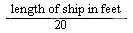 and the inner bottom shall be continued out to the ship's sides in such a manner as to protect the bottom to the turn of the bilge. The inner bottom shall be deemed to be adequate for this purpose if the line of intersection of the outer edge of the margin plate with the bilge plating is not lower at any point than a horizontal plane passing through the point of intersection with the frame line amidships of a transverse diagonal line inclined at 25 degrees to the base line and cutting it at a point one-half of the ship's moulded breadth from the centre line.