S.I. No. 108/1963 - Wireless Telegraphy (Control of Interference From Electric Motors) Regulations, 1963.
S.I. No. 108 of 1963. | ||
WIRELESS TELEGRAPHY (CONTROL OF INTERFERENCE FROM ELECTRIC MOTORS) REGULATIONS, 1963. | ||
I, MICHAEL HILLIARD, Minister for Posts and Telegraphs, in exercise of the powers conferred on me by section 12A (inserted by the Broadcasting Authority Act, 1960 (No. 10 of 1960) ) of the Wireless Telegraphy Act, 1926 (No. 45 of 1926), hereby make the following Regulations : | ||
|
1 Short title and commencement. | 1. (1) These Regulations may be cited as the Wireless Telegraphy (Control of Interference from Electric Motors) Regulations, 1963. | |
(2) These Regulations shall come into force on the 1st December, 1963. | ||
|
2 Interpretation. | 2. The Interpretation Act, 1937 (No. 38 of 1937), applies these Regulations. | |
|
3 Definitions. | 3. In these Regulations— | |
" electric motor " means— | ||
(a) an electric motor having a continuous rating of less than 1 horse power per 1,000 revolutions per minute, or | ||
(b) a generator or converter having a continuous rating of less than 0.75 kilowatt or kilo-volt-ampere per 1,000 revolutions per minute, | ||
and includes any switchgear or controlling apparatus directly associated with such motor, generator or converter; | ||
" electric supply lines " in relation to— | ||
(a) an electric motor which is a generator means electric lines for transmitting the electric power generated thereby, | ||
(b) an electric motor which is a converter means electric lines for transmitting electric power thereto and electric lines for transmitting the electric power therefrom, | ||
(c) any other electric motor means electric lines for transmitting electric power thereto; | ||
" electric supply line terminals " in relation to an electric motor means the terminals which are designed to connect the motor with electric supply lines either by a permanent or by a non-permanent connection, being in the former ease terminals mounted in or on the electric motor, and in the latter case the terminals at the point of the non-permanent connection; | ||
" suppressor " means a piece of equipment designed to reduce the electro-magnetic energy radiated from the apparatus or injected into any electric line by the apparatus, to which that piece of equipment is fitted, when the apparatus is operating; | ||
expressions used in the Schedule hereto have the meanings respectively assigned to them in Part 1 of that Schedule. | ||
|
4 Application. | 4. These Regulations shall apply to any electric motor if— | |
(a) it is to be used or | ||
(b) it is to be sold otherwise than for export, or offered or advertised for sale otherwise than for export, or let on hire or offered or advertised for letting on hire, by any person who in the course of business manufactures, assembles or imports electric motors. | ||
|
5 Limits of interference. | 5. An electric motor shall be so designed, constructed, assembled and installed, and such precautions shall be taken in relation to it (by means of the fitting of a suppressor or otherwise), as to ensure that when used— | |
(a) the voltage of electro-magnetic energy at the electric supply line terminals of the electric motor, as measured and computed in accordance with Regulation 6 of these Regulations shall not exceed— | ||
(i) one thousand five hundred microvolts where the measurement is made at a frequency of one hundred and fifty kilocycles per second or at any frequency exceeding one hundred and fifty kilocycles and not exceeding thirty megacycles per second, | ||
(ii) seven hundred and fifty microvolts where the measurement is made at any frequency exceeding thirty megacycles and not exceeding one hundred megacycles per second, | ||
(iii) one thousand five hundred microvolts where the measurement is made at any frequency exceeding one hundred megacycles and not exceeding two hundred and twenty-three megacycles per second; and | ||
(b) the field strength of the electro-magnetic energy radiated in any direction from the electric motor, as measured and computed in accordance with Regulation 6 of these Regulations, shall not exceed— | ||
(i) one hundred microvolts per metre where the measurement is made at a frequency of one hundred and fifty kilocycles per second or at any frequency exceeding one hundred and fifty kilocycles and not exceeding thirty megacycles per second, | ||
(ii) fifty microvolts per metre where the measurement is made at any frequency exceeding thirty megacycles and not exceeding one hundred megacycles per second, | ||
(iii) one hundred microvolts per metre where the measurement is made at any frequency exceeding one hundred megacycles and not exceeding two hundred and twenty-three megacycles per second, | ||
at any distance of not less than thirty-three feet measured as specified in paragraph 4 of Part 5 of the Schedule hereto. | ||
|
6 Voltage and field strength measurement. | 6. (1) For the purpose of measuring and computing the voltage and the field strength of such electro-magnetic energy at the frequencies mentioned in subparagraph (i) of paragraph (a) and subparagraph (i) of paragraph (b) of Regulation 5 of these Regulations the electric motor shall be tested by means of measuring apparatus of the description and having the physical and electrical characteristics and performance set out in Part 3 of the Schedule hereto. | |
(2) For the purpose of measuring and computing the said voltage and field strength at the frequencies mentioned in subparagraphs (ii) and (iii) of paragraph (a) and subparagraphs (ii) and (iii) of paragraph (b) of Regulation 5 of these Regulations, the electric motor shall be tested by means of measuring apparatus of the description and having the physical and electrical characteristics and performance set out in Part 2 of the Schedule hereto. | ||
(3) The tests for voltage shall be made by the method and under the conditions set out in Part 4 of the Schedule hereto, and the tests for field strength shall be made by the method and under the conditions set out in Part 5 of that Schedule. | ||
(4) The said voltage and field strength shall be computed as provided in Part 4 or Part 5 (as the case may be) of the Schedule hereto from the readings afforded by the measuring apparatus while the electric motor is operating. | ||
|
THE SCHEDULE. | ||
PART 1. | ||
DEFINITION OF EXPRESSIONS USED IN THE SCHEDULE. | ||
Voltage and e.m.f. | ||
References to the voltage or e.m.f. of a sinewave are references to its effective or root mean square value. | ||
Decibel means a unit of transmission giving the ratio of two powers. If P1 and P2 represent two values of power and n the number of decibels representing their ratio then n=10 log10 P1/P2. If the two powers are dissipated in equal resistive impedances their ratio in decibels may be expressed by n=20 log10 V1/V2 where V1 and V2 are the voltages across the two resistive impedances. | ||
Applied voltage means the voltage applied to the input terminals of the measuring apparatus. | ||
Terminal voltage means the radio frequency voltage present between each electric supply line terminal of an electric motor and the screen of the measuring apparatus. | ||
Reference deflection means the deflection of the needle of the indicating meter of the valve-voltmeter to a mark at the middle of the scale of the meter. | ||
Tuned frequency means the mid-frequency of the band of frequencies for which the measuring apparatus is tuned to accept the applied voltage. | ||
Intermediate frequency means the mid-frequency of the band of frequencies for which the intermediate frequency amplifier of the measuring apparatus is tuned to accept the voltage applied to it. | ||
Image frequency means the frequency, not being the tuned frequency, which combines with the fundamental frequency of the local oscillator to produce the intermediate frequency. | ||
Terminal voltage calibration constant means the number of decibels that must be added to the reading of the measuring apparatus, when a measurement of terminal voltage is made as prescribed, to give the terminal voltage in decibels above one microvolt. | ||
Field strength calibration constant means the number of decibels that must be added to the reading of the measuring apparatus, when a measurement of field strength is made as prescribed, to give the value of field strength in decibels above one microvolt per metre. | ||
PART 2. | ||
DESCRIPTION AND SPECIFICATION OF CHARACTERISTICS AND PERFORMANCE OF MEASURING APPARATUS FOR USE AT FREQUENCIES EXCEEDING 30 MC/S AND NOT EXCEEDING 223 MC/S. | ||
1. General description | ||
(1) The measuring apparatus shall be a calibrated radio receiver, designed for the measurement of radio frequency noise voltages and the field strength of radio frequency noise. For this latter purpose the input terminals of the receiver shall be connected to a dipole aerial by a balanced screened feeder. The receiver shall be of the superheterodyne type and comprise a radio-frequency (R.F.) amplifier, a frequency changer, an intermediate-frequency (I.F.) amplifier and an output valve-voltmeter. Attenuators, calibrated in decibels (db), shall be provided in the input circuits of both R.F. and I.F. amplifiers. The indicating meter of the valve-voltmeter shall have a scale provided with zero and full-scale marks and a reference deflection mark at mid-scale. The measuring apparatus shall be calibrated in terms of a known sinewave voltage at its input terminals and in terms of a known intensity of a continuous wave field in which the associated aerial system is placed. Facilities shall be provided so that, whenever a measurement is to be made, the gain of the receiver of the measuring apparatus may be set to the gain used when it was calibrated. | ||
(2) For the purpose of terminal voltage tests, resistive networks shall be provided, one for connection between each electric supply line terminal (other than that to which the measuring apparatus is to be connected) and earth via an isolating capacitor. An isolating capacitor shall also be provided for connection between the measuring apparatus and the supply line terminal to be tested. Each resistive network shall have a resistance of 75 ohms ( ± 15 ohms) and a phase angle not exceeding 30 degrees. Each isolatingcapacitor shall have an impedance of less than 5 ohms at the frequencies at which the measurements are to be made. An unbalance/balance transformer may be inserted in the connection between the appropriate isolating capacitor and the measuring apparatus, and if so any loss caused by it shall be included in the calibration of the measuring apparatus. | ||
(3) For the purpose of terminal voltage tests, reactors having an impedance of not less than 500 ohms at the frequencies at which the measurements are to be made shall be provided for insertion between the electric supply line terminals of the electric motor and the electric supply lines. Filters may be inserted between the reactors and the supply lines if required for reducing noise voltages present on the supply lines. | ||
2. Performance characteristics | ||
(1) Accuracy of setting frequency. The measuring apparatus shall be capable of being set, to an accuracy of ± 1 per cent., to receive any frequency within its range. | ||
(2) Sensitivity and accuracy of measuring apparatus—Voltage measurement. At any frequency within the range of the measuring apparatus, values of sinewave voltage greater than 20 microvolts shall be measurable to an accuracy of ± 1 db. | ||
(3) Sensitivity and accuracy of measuring apparatus—Field strength measurement. Values of field strength greater than 20 microvolts per metre, at any frequency within the range of the measuring apparatus, shall be measurable to an accuracy of ± 3 db. | ||
(4) Attenuators. The calibrated attenuators shall be so constructed and disposed that no performance characteristic of the set, apart from gain, is significantly affected by variations in their settings. | ||
(5) Overload characteristic. With the measuring apparatus adjusted to give reference deflection of the meter for an applied sinewave voltage of any value between 20 microvolts and 100 millivolts, the sinewave voltage measured at the input of the valve-voltmeter shall be proportional to the applied voltage within ± 1 db up to a voltage 40 db above that producing reference deflection. | ||
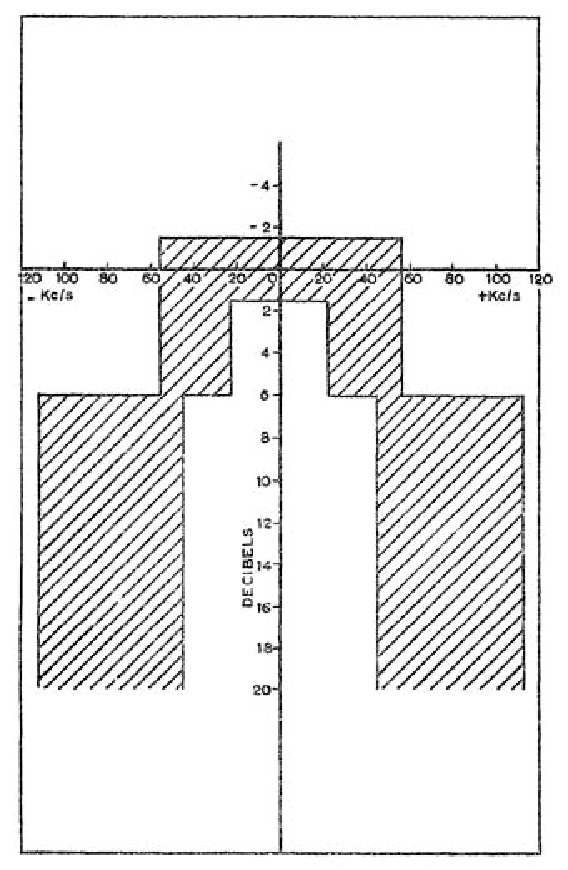
(6) Overall frequency characteristic. The variation with frequency of an applied sinewave voltage to produce a constant voltage at the input to the valve-voltmeter, when no alteration is made to the tuning of the measuring apparatus, shall not exceed the limits of the shaded area of Figure 1. | ||
FIG. 1. —Overall Frequency Characteristic of Measuring Apparatus—Schedule Part 2, Paragraph 2 (6). | ||
| ||
(7) Frequency characteristic of the radio-frequency amplifier. The increase of an applied sinewave voltage needed to produce a constant voltage at the control grid of the frequency changer valve shall be not less than 6 db when the frequency of the applied voltage is varied from the tuned frequency by ± 2.5 Mc/s. | ||
(8) Spurious responses. The applied sinewave voltage of the tuned frequency which produces reference deflection of the meter shall be at least 80 db lower than the applied voltage at any other frequency which combines with a harmonic and not the fundamental frequency of the local oscillator to produce reference deflection. | ||
(9) Image frequency response. The ratio of the applied sine-wave voltages which produce reference deflection at the image frequency and at the tuned frequency respectively shall be at least 40 db. | ||
(10) Intermediate frequency response. The ratio of the applied sinewave voltages which produce reference deflection at the intermediate frequency and at the tuned frequency respectively shall be at least 40 db. | ||
(11) Screening. The overall screening shall be such that, with the receiver tuned to any frequency within its range and the gain of the receiver adjusted to that used for that frequency when the measuring apparatus was calibrated, the change in the I.F. attenuator setting required to return the meter to reference deflection when an external electro-magnetic field of that frequency and of a strength of 86 db above 1 microvolt per metre is switched on shall not exceed 1 db. This requirement shall be met for all orientations of the measuring apparatus. For this test screening covers may be placed over the input terminals. | ||
3. Input circuit | ||
The impedance at the input terminals of the measuring apparatus shall be balanced and shall have a value of 75 ± 15 ohms and a phase angle within the limits ± 20 degrees at any frequency within the range of the measuring apparatus. | ||
4. Aerial and feeder | ||
(1) Aerial. The aerial shall consist of a dipole of a length not greater than 3 metres nor less than 0.75 metres, which shall be supported so that its centre is not less than 2 metres above the base of the support when a measurement of field-strength is made. | ||
(2) Feeder. The aerial shall be connected to the aerial input terminals of the measuring apparatus by a twin balanced and screened feeder of a nominal characteristic impedance of 75 ohms. The feeder shall be led at right angles from the dipole for a distance of at least 1 metre. | ||
(3) Balance/Unbalance ratio. The balance/unbalance ratio at the aerial end of the feeder shall be not less than 20 db when measured as follows:— | ||
A generator of internal impedance R where R is not greater than 5 ohms, shall be connected to the feeder and measuring apparatus as shown in Figure 2 (a) and as shown in Figure 2 (b) in turn. The ratio | ||
5. Output circuit (valve-voltmeter) | ||
(1) Linearity. The performance of the rectifier and of any associated circuits of the valve-voltmeter shall be such that the current through the indicating meter is linearly related to the sinewave voltage input to the rectifer, to within ± 10 per cent. of that voltage, for all values of input voltage from 0.5 to 2.5 times the value producing reference deflection. | ||
The application to the input of the rectifier of the sinewave voltage which produces reference deflection shall cause an increase of 1.75 volts ± 10 per cent. in the steady voltage across the rectifier load. | ||
The increase in the sinewave voltage at the input of the rectifier required to increase the meter reading from reference deflection to full-scale deflection shall be not less than 5.5 db nor more than 6.5 db. | ||
(2) Charge time-constant. A sinusoidal voltage of frequency equal to the intermediate frequency, which when continuously applied to the input terminals of the intermediate frequency amplifier produces reference deflection, shall, when suddenly applied at the same point, cause the change of voltage across the output circuit of the rectifier to reach 0.63 times the final value of the change of voltage in not less than 0.8 milliseconds and not more than 1.2 milliseconds. | ||
In this test, the input terminals of the I.F. amplifier shall be disconnected from the preceding circuits of the measuring apparatus. | ||
(3) Discharge time-constant. The time taken for the current in the meter circut to decrease by 0.63 times its initial value after anapplied voltage as specified in paragraph 5 (2) above is suddenly removed shall be not less than 450 milliseconds and not more than 550 milliseconds. | ||
FIG. 2. —Schedule Part 2, Paragraph 4 (3). | ||
| ||
(4) Indicating meter. The indicating meter shall be of the permanent magnet moving-coil type in which the deflection of the needle is directly proportional to the current passing through the meter. Under the conditions of use of the measuring apparatus the damping of the meter shall be such that, when a current of a value which produces a final steady full-scale deflection is suddenly applied to the meter, the time of rise to 80 per cent. of full-scale deflection is not less than 240 milliseconds and not more than 360 milliseconds and the overswing is less than 5 per cent. of the full-scale deflection. | ||
6. General requirements | ||
(1) Gain setting. The accuracy of adjustment of the measuring apparatus shall be such that two successive measurements of any given input voltage (having a value within the range of measurement of the apparatus), between which any adjustment of the operating controls may be made, shall not differ by more than 1 db. | ||
(2) Monitoring. Provision shall be made for aural presentation of the receiver output for monitoring purposes. | ||
PART 3. | ||
DESCRIPTION AND SPECIFICATION OF CHARACTERISTICS AND PERFORMANCE OF MEASURING APPARATUS FOR USE IN THE FREQUENCY RANGES150 KC/s TO 30 Mc/s. | ||
1. General description | ||
(1) The measuring apparatus shall be a calibrated radio receiver, designed for the measurement of radio frequency noise voltages, and the field strength of radio frequency noise. For this latter purpose the input terminal of that receiver shall be connected directly to a vertical rod aerial. The receiver shall be of the superheterodyne type and comprise a radio-frequency (R.F.) amplifier, a frequency-changer, an intermediate-frequency (I.F.) amplifier and an output valve-voltmeter. One or more stepped or continuously-variable attenuators, calibrated in decibels (db), shall be provided, either wholly in the input circuit of the R.F. amplifier, or distributed between the input circuits of the R.F. and I.F. amplifiers. If any of the attenuators are continuously-variable, the indicating meter of the valve-voltmetershall have a scale provided with zero and full-scale marks and a reference deflection mark at mid-scale. If none of the attenuators is continuously-variable, the indicating meter of the valve-voltmeter shall have a scale provided with zero and full-scale marks and calibrated in steps of 1 db, covering a range at least equal to the smallest step on the attenuator(s). The measuring apparatus shall be calibrated in terms of a known sinewave voltage applied across the 75 ohm resistive network mentioned in the next subparagraph and the input circuit of the measuring apparatus (the two being connected in series), and in terms of a known intensity of a continuous wave field in which the associated aerial system is placed. Facilities shall be provided so that whenever a measurement is to be made, the gain of the receiver of the measuring apparatus may be set to the gain used when it was calibrated. | ||
(2) For the purpose of terminal voltage tests, resistive networks shall be provided, one for connection between the electric supply line terminal to be tested and one terminal of the input circuit of the measuring apparatus via an isolating capacitor and one for connection between each other electric supply line terminal and earth via an isolating capacitor. The former resistive network shall have a resistance of 75 ohms (± 15 ohms) and a phase angle not exceeding 30 degrees. Each of the latter resistive networks shall have a resistance of 150 ohms (± 30 ohms) and a phase angle not exceeding 30 degrees. Each isolating capacitor shall have an impedance of less than 10 ohms at the frequencies at which the measurements are to be made. | ||
(3) For the purpose of terminal voltage tests, reactors having an impedance of not less than 1000 ohms at the frequencies at which the measurements are to be made shall be provided for insertion between the electric supply line terminal of the electric motor and the electric supply lines. Filters may be inserted between the reactors and the supply lines if required for reducing noise voltages present on the supply lines. | ||
2. Performance characteristics | ||
(1) Accuracy of setting frequency. The measuring set shall be capable of being set, to an accuracy of ± 1 per cent. to receive any frequency within its range. | ||
(2) Sensitivity and accuracy of measuring apparatus—voltage measurement. At any frequency within the range of the measuring apparatus, values of sinewave voltage greater than 4 microvolts shall be measurable to an accuracy of ± 1 db. | ||
(3) Sensitivity and accuracy of measuring apparatus—field strength measurement. Values of field strength greater than 50 microvolts per metre, at any frequency within the range of the measuring apparatus, shall be measurable with an accuracy of ± 3 db. | ||
(4) Attenuators. The calibrated attenuators shall be so constructed and disposed that no performance characteristic of the set, apart from gain, is significantly affected by variations in their settings. | ||
(5) Overload characteristic. With the measuring apparatus adjusted to give full-scale deflection of the meter for an applied sinewave voltage of any value between 4 microvolts and 40 millivolts, the sinewave voltage measured at the input of the valve-voltmeter shall be proportional to the applied voltage within ±1 db up to a voltage 20 db above that producing full-scale deflection of the meter. | ||
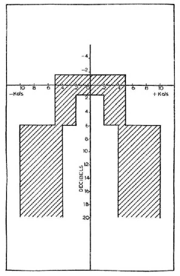
(6) Overall frequency characteristic. The variation with frequency of an applied sinewave voltage to produce a constant voltage at the input to the valve-voltmeter, when no alteration is made to the tuning of the measuring apparatus, shall not exceed the limits of the shaded area of Figure 3. | ||
(7) Frequency characteristic of the input circuit. The acceptance bandwidth of the input circuits prior to the first valve when measured at the input terminals shall be not greater than the tuned frequency for an attenuation of 20 db relative to the response at the tuned frequency. | ||
(8) Frequency characteristic of the radio frequency amplifier. The acceptance bandwidth of the signal frequency circuits prior to the frequency changer valve when measured at the input terminals shall be not greater than the intermediate frequency for an attenuation of 20 db relative to the response at the tuned frequency. | ||
(9) Spurious responses. The applied sinewave voltage of the tuned frequency which produces full-scale deflection of the meter shall be at least 80 db lower than the applied voltage at any other frequency which combines with a harmonic and not the fundamental frequency of the local oscillator to produce full-scale deflection. | ||
(10) Image frequency response. The ratio of the applied sine-wave voltages which produce full-scale deflection of the meter at the image frequency and at the tuned frequency respectively shall be at least 40 db. | ||
FIG. 3.—Overall Frequency Characteristic of Measuring Apparatus—Schedule Part 3, Paragraph 2 (6). | ||
| ||
(11) Intermediate frequency response. The ratio of the applied sinewave voltages which produce full-scale deflection of the meter at the intermediate frequency and at the tuned frequency respectively shall be at least : | ||
(a) 40 db where the tuned frequency differs from the inter mediate frequency by more than 250 kc/s. | ||
(b) 20 db where the tuned frequency differs from the intermediate frequency by more than 150 kc/s, but not more than 250 kc/s. | ||
(12) Screening. The overall screening shall be such that, with the receiver tuned to any frequency within its range and the gain of the receiver adjusted to that used for that frequency when the measuring apparatus was calibrated, the meter indication shall not vary by more than 1 db when an electro-magnetic field of that frequency and of a strength of 30 millivolts per metre is switched on. | ||
3. Aerial | ||
The aerial shall consist of a vertical rod of a total length not exceeding 2 metres. | ||
4. Input circuit | ||
The measuring apparatus shall have an unbalanced input termination for making terminal voltage measurements. The impedance at the input terminals shall have a value of 75 ohms ± 15 ohms and a phase angle within the limits ± 10 degrees at any frequency within the range of the measuring apparatus. | ||
5. Output circuit (valve-voltmeter) | ||
(1) Linearity. The performance of the rectifier and of any associated circuits of the valve-voltmeter shall be such that the current through the indicating meter is linearly related to the sinewave voltage input to the rectifier, to within ± 10 per cent. of that voltage for all values of input voltage from 0.3 to 4 times the value producing full-scale deflection of the meter. | ||
The application to the input of the rectifier of the sinewave voltage which produces full-scale deflection shall cause an increase of 5.5 volts ± 10 per cent. in the steady voltage across the rectifier load. | ||
(2) Charge time-constant. A sinusoidal voltage of frequency equal to the intermediate frequency, which when continuously applied to the input terminals of the intermediate frequency amplifier produces full-scale deflection of the meter, shall, when suddenly applied at the same point, cause the change of voltageacross the output circuit of the rectifier to reach 0.63 times the final value of the change of voltage in not less than 0.8 milliseconds and not more than 1.2 milliseconds. | ||
In this test, the input terminals of the I.F. amplifier shall be disconnected from the preceding circuits of the measuring apparatus. | ||
(3) Discharge time-constant. The time taken for the current in the meter circuit to decrease by 0.63 times its initial value after an applied voltage as specified in paragraph 5 (2) above is suddenly removed shall be not less than 450 milliseconds and not more than 550 milliseconds. | ||
(4) Indicating meter. The indicating meter shall be of the permanent magnet moving coil type in which the deflection of the needle is directly proportional to the current passing through the meter. Under the conditions of use of the measuring apparatus the damping of the meter shall be such that, when a current of a value which produces a final steady full-scale deflection is suddenly applied to the meter, the time of rise of 80 per cent. of full-scale deflection is not less than 240 milliseconds and not more than 360 milliseconds and the overswing is less than 5 per cent. of the full-scale deflection. | ||
6. General requirements | ||
(1) Gain setting. The accuracy of adjustment of the measuring apparatus shall be such that two successive measurements of any given input voltage (having a value within the range of measurement of the apparatus), between which any adjustments of the operating controls may be made, shall not differ by more than 1 db. | ||
(2) Monitoring. Provision shall be made for the aural presentation of the receiver output for monitoring purposes. | ||
PART 4. | ||
Method and conditions of measuring terminal voltage. | ||
1. General | ||
The electric motor under test shall, so far as is consistent with the following paragraphs of this Part of the Schedule, be tested under its normal conditions of installation and use. Where it is normally incorporated in any apparatus, appliance, or machine, it shall be tested as so incorporated. | ||
2. Connection of electric motor to electric supply lines | ||
The electric supply line terminals of the electric motor under test shall be connected with the resistive networks mentioned in paragraph 1 (2) of Part 2 or Part 3 (as the case may be) of the Schedule, and, through the reactors (and, if required, the filters) mentioned in paragraph 1 (3) of Part 2 or Part 3 (as the case may be) of the Schedule, with the electric supply lines to which the electric motor is connected in normal use. The leads between the electric supply line terminals and the reactors shall be as short as is practicable and unscreened. The layout and wiring of the electric motor shall not be altered more than is necessary to comply with this Part of the Schedule. | ||
3. Preliminary adjustment of measuring apparatus | ||
The receiver of the measuring apparatus shall be connected with an appropriate source of electricity supply, the attenuator(s) shall be set at maximum loss, and the zero control of the valve-voltmeter shall be adjusted to bring the needle of the indicating meter to the zero mark. The receiver shall be tuned to the frequency, as indicated by the main tuning dial calibrations, at which it is desired to make the measurement, and its gain shall be set to that used when the measuring apparatus was calibrated. | ||
4. Input connection of measuring apparatus | ||
(1) Where the measuring apparatus being used is that described in Part 2 of the Schedule, one of the receiver input terminals of the measuring apparatus shall be connected with one of the electric supply line terminals of the electric motor via the isolating capacitor, and the other receiver input terminal shall be connected to earth. The other electric supply line terminals shall be connected to earth through the 75 ohms resistive networks mentioned in paragraph 1 (2) of Part 2 of the Schedule. | ||
(2) Where the measuring apparatus being used is that described in Part 3 of the Schedule, one of the receiver input terminals of the measuring apparatus shall be connected with one of the electric supply line terminals of the electric motor through the 75 ohms resistive network and isolating capacitor mentioned in paragraph 1 (2) of Part 3 of the Schedule and the other receiver input terminal shall be connected to earth. The other supply line terminals shall be connected to earth through the 150 ohms resistive networks mentioned in that paragraph. | ||
(3) The shortest practicable length of unscreened connecting lead shall be used. | ||
5. Making the measurement | ||
(1) The R.F. amplifier tuning of the receiver shall be adjusted to give maximum deflection of the meter needle. | ||
(2) Where the measuring apparatus being used is that described in Part 2 of the Schedule, the attenuators shall then be adjusted to bring the meter needle to the reference deflection mark, the R.F. attenuator being adjusted so that the I.F. attenuator is set to the lowest possible value in excess of 10 db. | ||
(3) Where the measuring apparatus being used is that described in Part 3 of the Schedule, the attenuator(s) shall be adjusted to bring the meter needle to the reference deflection mark if a continuously-variable attenuator is fitted, or otherwise on to the calibrated part of the scale. | ||
6. Interpretation of results | ||
The voltage between the electric supply line terminal of the electric motor with which the receiver is connected and earth, expressed in decibels above 1 microvolt, will be given by the sum of : | ||
(a) the reading(s) of the attenuator(s), | ||
(b) the calibration constant (if any) appropriate to the frequency at which the measurement is being made, and | ||
(c) the reading of the meter, if calibrated in decibels. If the result obtained is x decibels, the voltage expressed in microvolts is given by the antilog to the base 10 of | ||
7. Tests | ||
A set of tests shall be made in each case, as follows: | ||
(a) A check test made while the electric motor is not operating. | ||
(b) A main test which shall include readings taken while the electric motor is operating and at times when the switch-gear (if any) of the electric motor is bringing the motor into and out of operation and when the controlling apparatus (if any) of the electric motor is operating. | ||
(c) A further check test as mentioned in (a). | ||
This set of tests shall be made first with the receiver connected with one of the electric supply line terminals of the electric motor, and shall be repeated with the receiver connected with the other (or each of the others) of such terminals in accordance with paragraph 4 of Part 4 of the Schedule. | ||
8. If a click (as opposed to a buzz of appreciable duration) is heard in the monitoring loudspeaker or earphones at any time when the switchgear or controlling apparatus of the electric motor is operating, then provided that not more than one further click is heard during the period of two seconds immediately following the first, the readings of the measuring apparatus appearing within that period of two seconds shall be disregarded for the purpose of these Regulations. | ||
9. If the maximum reading obtained on any main test exceeds the maximum reading obtained on either of the check tests made next before or next after that main test by at least 10 db, the readings obtained on that main test are to be regarded as not materially affected by extraneous noise or signals. Otherwise the readings obtained on that main test are to be regarded as materially affected by extraneous noise or signals, and the results of that main test shall be disregarded for the purpose of these Regulations. | ||
PART 5. | ||
METHOD AND CONDITIONS OF MEASURING FIELD STRENGTH. | ||
1. General | ||
The electric motor under test shall, so far as is consistent with the following paragraphs of this Part of the Schedule, be tested under its normal conditions of installation and use. Where it is normally incorporated in any apparatus, appliance, or machine, it shall be tested as so incorporated. | ||
2. Connection of electric motor to electric supply lines | ||
Paragraph 2 of Part 4 of the Schedule shall apply. The measuring apparatus shall be substituted by a resistive network having a value of 75 ± 15 ohms and a phase angle within the limits ± 20 degrees. | ||
3. Other electrical apparatus to be disconnected | ||
All electrical apparatus (other than the electric motor under test and any apparatus, appliance, or machine in which it isincorporated) which is installed in proximity to the electric motor, and which in operation could appreciably affect the result of the test, shall be switched off or otherwise prevented from being energised by complete or partial electrical disconnection. | ||
4. Distance of aerial | ||
The distance between the aerial of the measuring apparatus and the nearest point on the electric motor under test (or, as the case may be, on any apparatus, appliance, or machine in which it is incorporated) shall be not less than 33 feet. | ||
5. Orientation of aerial | ||
In the frequency range 30 Mc/s to 223 Mc/s the aerial may be oriented in any position for purpose of the measurement. | ||
6. Preliminary adjustment of measuring apparatus | ||
Paragraph 3 of Part 4 of the Schedule shall apply. | ||
7. Input connection of measuring apparatus | ||
The receiver shall be connected to the aerial and feeder mentioned in paragraph 4 of Part 2 of the Schedule, or the aerial mentioned in paragraph 3 of Part 3 of the Schedule (as the case may be). | ||
8. Making the measurement | ||
Paragraph 5 of Part 4 of the Schedule shall apply. | ||
9. Interpretation of results | ||
The field strength expressed in decibels above 1 microvolt per metre will be given by the sum of : | ||
(a) the reading(s) of the attenuator(s), | ||
(b) the field strength calibration constant (if any) appropriate to the frequency at which the measurement is being made, and | ||
(c) the reading of the meter, if calibrated in decibels. If the result obtained is x decibels, the field strength expressed in microvolts per metre is given by the antilog to the base 10 of | ||
10. Tests | ||
A set of tests as mentioned in subparagraphs (a), (b) and (c) of paragraph 7 of Part 4 of the Schedule shall be made in each case, and paragraphs 8 and 9 of the said Part 4 shall apply. | ||
GIVEN under my Official Seal, this 6th day of June, 1963. | ||
MICHAEL HILLIARD. | ||
EXPLANATORY NOTE. | ||
These Regulations provide the requirements to be complied with by manufacturers, assemblers, importers and users of certain electric motors, generators and converters within the State for the purpose of ensuring that they will not cause undue interference with radio and television reception. | ||
The requirement is prescribed in terms of the maximum permitted voltage of electro-magnetic energy within specified frequencies at the supply line terminals, and the maximum permitted field strength of the electro-magnetic energy radiated within those frequencies. The Schedule sets out the method of measuring the terminal voltage and field strength, the conditions under which tests are to be made, and the description and specification of the measuring apparatus. |
 of the generator e.m.f.'s which produce reference deflection of the meter in the unbalanced connection, (e1 Figure 2 (a)) and the balanced connection (e2 Figure 2 (b)) respectively shall be taken as the balance/unbalance ratio.
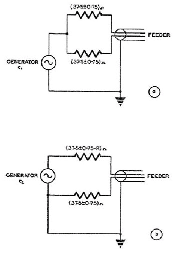

 .
.