S.I. No. 30/1950 - Standard Specification (Electrical Plugs and Socket-Outlets (10 Ampere Continental Type)) Order, 1950.
S.I. No. 30 of 1950. | ||||||||||
STANDARD SPECIFICATION (ELECTRICAL PLUGS AND SOCKET-OUTLETS (10 AMPERE CONTINENTAL TYPE)) ORDER, 1950. | ||||||||||
I, DANIEL MORRISSEY, Minister for Industry and Commerce, in exercise of the powers conferred on me by subsection (3) of section 20 of the Industrial Research and Standards Act, 1946 (No. 25 of 1946), hereby order as follows : 1. This Order may be cited as the Standard Specification (Electrical Plugs and Socket-Outlets (10 Ampere Continental Type)) Order, 1950. 2.—(1) The specification set forth in Part II of the Schedule to this Order is hereby declared to be the standard specification for the commodity described in Part I of the said Schedule. | ||||||||||
(2) The said standard specification may be cited as Irish Standard 23 : 1950. | ||||||||||
|
SCHEDULE. | ||||||||||
PART I. | ||||||||||
ELECTRICAL PLUGS AND SOCKET-OUTLETS (10 AMPERE CONTINENTAL TYPE). | ||||||||||
PART II. | ||||||||||
SPECIFICATION. | ||||||||||
In this specification, the letters B.S., when followed by two sets of numbers, refer to the British Standard of which the first is the serial number and the second is the year of its publication by the British Standards Institution. | ||||||||||
SECTION I. | ||||||||||
Plugs and Socket-outlets (Non-earthing Type). | ||||||||||
DEFINITIONS. | ||||||||||
1. For the purpose of Section I of this specification the following definitions shall apply :— | ||||||||||
(a) Plug :—A device carrying two metallic contacts in the form of cylindrical pins arranged for connection to a two-core flexible cable. | ||||||||||
(b) Socket-outlet :—A device carrying two metallic contacts designed to engage with the corresponding pins of a plug and arranged for connection to fixed wiring, and suitable for fixing to a flat surface. | ||||||||||
(c) Contact-tubes :—The metallic contacts in the socket-outlet which engage with the pins of the plug. | ||||||||||
(d) Voltage-carrying parts :—Metal parts in electrical contact with either pin of the plug or with either contact-tube of the socket-outlet. | ||||||||||
RATING. | ||||||||||
2. The plugs and socket-outlets shall be suitable for carrying 10 amperes at 250 volts. | ||||||||||
INTERCHANGEABILITY. | ||||||||||
3. Nothing in the construction of plugs and socket-outlets made to conform to Section I of this specification shall prevent their interchangeability amongst themselves. | ||||||||||
PREVENTION OF ACCIDENTAL CONTACT. | ||||||||||
4. The plugs and socket-outlets shall be designed to prevent accidental contact with their live parts. | ||||||||||
The contact-tubes shall be sunk below the surface of the cover of the socket-outlet in such a way as to render it impossible for the contact-tubes to be touched unintentionally. | ||||||||||
When the plug and socket-outlet are in engagement no voltage-carrying metallic part shall be accessible. | ||||||||||
TYPE AND SIZES OF TERMINALS. | ||||||||||
5. The terminals of pins shall be of the screw type and shall be capable of taking at least one 2·5 sq. mm. conductor. | ||||||||||
The terminals of contact-tubes shall be of the screw type and shall be so arranged that when the socket-outlet is fixed in its service position the conductors can be securely connected to the terminals from the front. The socket-outlet shall be designed and all parts so arranged that two conductors of at least 2·5 sq. mm. each may be connected to each terminal. | ||||||||||
The full diameter of the screw thread of the terminal screws shall be at least 3·5 mm. | ||||||||||
SCREWS IN TERMINALS. | ||||||||||
6. The heads of screws in terminals shall have adequate slots and shall be easily accessible for tightening. Where heads of screws serve to bind the conductors to the terminals they shall be suitable for making the connections, and the screw heads shall enter a recess or enter between side projections. | ||||||||||
MATERIALS. | ||||||||||
7. Parts made of ferrous metal shall be rust resistant. | ||||||||||
Bases and covers of plugs and covers of socket-outlets shall be made of tough non-ignitable insulating materials that will not soften when heated to a temperature of 85°C. The resistance of such materials to moisture absorption shall not depend on glaze or varnish. | ||||||||||
The material used in the current-carrying parts shall be brass, phosphor-bronze, or other suitable material. | ||||||||||
CONSTRUCTION OF PINS AND TERMINALS OF PLUG. | ||||||||||
8. The pins shall be fixed in the insulating material so that they cannot turn or become detached when the plug is completely assembled. They shall be cylindrical and solid, with hemispherical ends to facilitate entry into the contact-tubes. The contact surface of pins shall be smooth and free from corrugations. Each pin and its terminal shall be formed in one piece or connected in such a way that they cannot work loose under normal service conditions. | ||||||||||
DIMENSIONS AND SPACING OF PINS OF PLUG. | ||||||||||
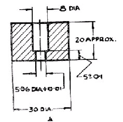
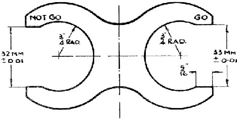
9. The dimensions of the pins and their spacing shall be such that they conform to the limits set by the " GO " and " NOT GO " gauges shown in Fig. 1. The weight of gauge A shall be 100 g. and in using it the only force applied shall be the weight of the gauge. | ||||||||||
DIMENSIONS OF PLUG. | ||||||||||
10. The plug shall be of such dimensions that it shall conform to the limits set by the " NOT GO " gauge shown in Fig. 2. | ||||||||||
CONSTRUCTION OF PLUG. | ||||||||||
11. The plug shall be designed to allow the flexible cable to enter through one hole, groove or gland. It shall be provided with a device for gripping any suitable cable together with its protective covering so as to prevent stress on the terminals. The device shall grip the cable in such a way as to prevent the protective covering from stripping and the conducting cores from unravelling. | ||||||||||
A finger grip or other suitable means shall be provided for inserting and withdrawing the plug without subjecting the flexible cable to any stress. | ||||||||||
CONTACT-TUBES OF SOCKET-OUTLET. | ||||||||||
12. The contact-tubes shall be so constructed as to ensure surface rather than line or point contact with the plug pins. The openings of the contact-tubes shall be so shaped as to provide easy entry and withdrawal of the plug pins. There shall be no tendency for the contact-tubes to bite into the plug pins. | ||||||||||
The contact-tubes shall be self-adjusting and free to align themselves so as to make and maintain by spring pressure, under normal service conditions, satisfactory contact with the pins of the plug. The means for producing the contact pressure shall be associated with each contact-tube independently. | ||||||||||
METHOD OF CONNECTING CONTACT-TUBES TO TERMINALS. | ||||||||||
13. Each contact-tube and its terminal shall be formed of one piece or connected in such a way that they cannot work loose under normal service conditions. | ||||||||||
FIXING-HOLES AND FIXING-SLOTS IN SOCKET-OUTLET. | ||||||||||
14. The fixing-holes or fixing-slots in the socket-outlet shall be suitable for size No. 6 wood screws conforming to B.S. 1200 : 1945. | ||||||||||
RECESS IN BASE OF SOCKET-OUTLET. | ||||||||||
15. The base of the socket-outlet shall be provided with a recess at the back to ensure proper seating when mounted. | ||||||||||
DIMENSIONS AND SPACING OF SOCKET-OUTLET. | ||||||||||
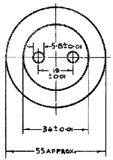
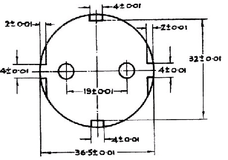
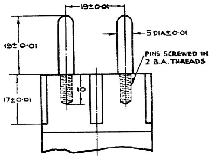
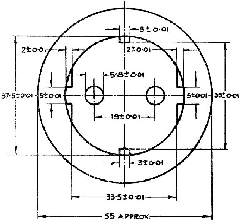
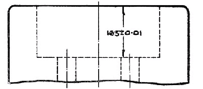
16. The spacing and alignment of the contact-tubes shall conform to the limits set by both pairs of pins of the " GO " gauge shown in Fig. 3. | ||||||||||
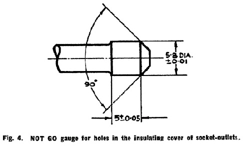
The holes in the insulating cover of the socket-outlet shall conform to the limits set by the " NOT GO " gauge shown in Fig. 4. | ||||||||||
SPRING PRESSURE OF CONTACT-TUBES OF SOCKET-OUTLET. | ||||||||||
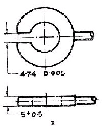
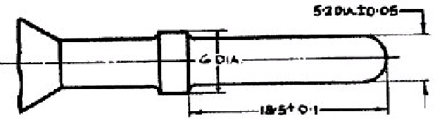
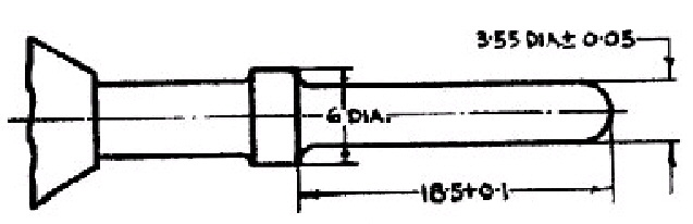
17. The contact-tubes of the socket-outlet shall permit the entry of gauge A shown in Fig. 5 and immediately after the withdrawal of this gauge shall in a vertical position support by spring pressure only the weight of gauge B shown in Fig. 5. The weight of gauge B shall be 250 g. | ||||||||||
BOSSES AND KNOCK-OUTS IN COVER OF SOCKET-OUTLET | ||||||||||
18. Bosses of adequate size and strength to take the cover fixing screws shall be provided in the covers of socket-outlets. | ||||||||||
Not less than two knock-outs of suitable size shall be provided. | ||||||||||
TESTING. | ||||||||||
19. Plugs and socket-outlets shall conform to the tests given in Clauses 20 to 25. | ||||||||||
VOLTAGE AND INSULATION TEST. | ||||||||||
20. The plugs and socket-outlets to be tested shall be stored for at least 8 hours in a test room at 15° C. to 20° C. so as to attain the temperature of the room. They shall then be exposed for 16 hours at the same temperature to air saturated with water vapour. | ||||||||||
The plug and socket-outlet shall then be engaged and a voltage of 1,500 R.M.S. volt A.C. shall be applied for one minute without a flash-over occurring : | ||||||||||
(i) between voltage-carrying parts and fixing screws, | ||||||||||
(ii) between voltage-carrying parts and a metal plate placed under the socket-outlet base, | ||||||||||
(iii) between voltage-carrying parts and a tinfoil wrapping placed around the plug, | ||||||||||
(iv) between the terminals of the socket-outlets. | ||||||||||
Immediately after completing these tests the insulation resistance of the plug and socket-outlet shall be determined between non-voltage-carrying metal parts and the terminals. The resistance shall be not less than 2 megohm with a D.C. voltage of 500 volt. | ||||||||||
HEAT TEST. | ||||||||||
21. The current-carrying parts of the plug and socket-outlet with the plug engaged shall be loaded with 12·5 ampere. If the voltage drop at a contact is greater than 50 milli volt, the following test shall be carried out : | ||||||||||
A ball of beeswax of about 3 mm. diameter shall be pressed on to each contact piece of the plug and socket-outlet. The plug and socket-outlet shall be engaged and enclosed in a cover at a temperature of 15° C. to 20° C. The current-carrying parts shall then be loaded for one hour with 12·5 ampere. During this period the contact pieces shall not have attained a temperature sufficient to melt the beeswax. | ||||||||||
TEST FOR CURRENT BREAKING CAPACITY. | ||||||||||
22. The plugs and socket-outlets shall be capable of breaking a current of 12·5 ampere when tested in a non-inductive D.C. circuit at 250 volts. | ||||||||||
The test shall be carried out at a temperature of 15° C. to 20° C. The socket-outlet shall be mounted on a vertical surface with the axes of the contact tubes in a vertical plane. All metal parts of the socket-outlet not in contact with voltage-carrying parts shall be earthed. The circuit shall be broken 20 times at intervals of half-a-minute by withdrawing the plug from the socket-outlet at a speed of approximately 6 inches per second. | ||||||||||
After a test has been completed the contact-tubes shall not have been appreciably attacked. | ||||||||||
TEST FOR MECHANICAL STRENGTH. | ||||||||||
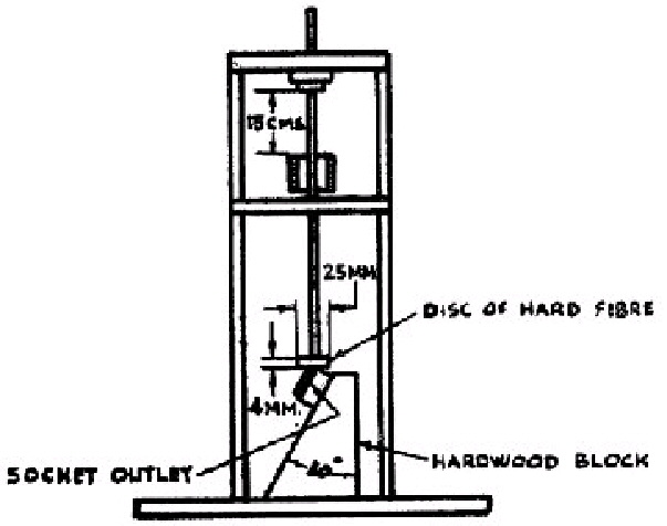
23. (a) The mechanical strength of the socket-outlet shall be tested by allowing a disc of hard fibre loaded to 250 g. to fall freely through 15 cm. on to the socket-outlet fixed rigidly to a hardwood block. The test shall be repeated for four different positions of the socket-outlet without cracks or impressions appearing on the covering. A suitable form of apparatus for the test is shown in Fig. 6. | ||||||||||
(b) The mechanical strength of the plug shall be tested by allowing it to fall freely three times through a quarter of a circle of 1 metre radius against a hard stop-plate. The plug shall suffer no damage as a result of the test, impressions on the insulating material not being considered as damage. | ||||||||||
The test may be carried out using an apparatus of the type shown in Fig. 7, the plug being fitted with a sufficient length of conductor connected as for service conditions. | ||||||||||
SERVICE TEST. | ||||||||||
24. The following tests shall be carried out after the plug and socket-outlet have undergone the test for current-breaking capacity set out in Clause 22. | ||||||||||
(a) The plug and socket-outlet, in service condition and position, shall be fixed in a 15 ampere 250 R.M.S. volt A.C. circuit, power factor 0·6 lagging. The plug shall be withdrawn 5,000 times at the rate of 15 withdrawals per minute. The polarity shall be reversed after 2,500 withdrawals. | ||||||||||
The socket-outlet shall withstand the test without showing any wear liable to be harmful in service, and without the openings to the contact-tubes having been appreciably attacked. Contact connections shall not have been loosened, nor shall insulation covering of voltage-carrying parts have suffered deterioration. | ||||||||||
(b) The socket-outlet, without prior subjection to moisture treatment, shall be capable of withstanding a voltage test as specified in Clause 20, using a voltage of 1,000 R.M.S. volt A.C. | ||||||||||
ACCIDENTAL CONTACT TEST. | ||||||||||
25. The cover of the socket-outlet shall be so constructed that when the socket-outlet is tested with the gauge shown in Fig. 8 contact between one pin of the gauge and one contact-tube of the socket-outlet shall not be possible without the second pin of the gauge entering the second hole of the cover. | ||||||||||
In carrying out the test the contact-tubes of the socket-outlet shall be vertical. The weight of the gauge shall be 250 g. and the only force applied shall be the weight of the gauge. | ||||||||||
MARKING. | ||||||||||
26. Plugs and socket-outlets shall be indelibly and distinctly marked to indicate that they are rated at 10 ampere 250 volt. | ||||||||||
SECTION II. | ||||||||||
Plugs and Socket-outlets (Earthing Type). | ||||||||||
DEFINITIONS. | ||||||||||
27. For the purpose of Section II of this specification the following definitions shall apply:— | ||||||||||
(a) Plug :—A device carrying three metallic contacts arranged for attachment to a three-core flexible cable. Two of the contacts shall form the normal current-carrying portion and shall be in the form of cylindrical pins. The third shall be for earthing or protective purposes, and shall constitute one element of a sliding pair. | ||||||||||
(b) Socket-outlet :—A device carrying three metallic contacts designed to engage with the corresponding contacts of a plug and arranged for connection to fixed wiring, and suitable for fixing to a flat surface. | ||||||||||
(c) Contact-tubes :—The metallic contacts in the socket-outlet which engage with the pins of the plug. | ||||||||||
(d) Voltage-carrying parts :—Metal parts in electrical contact with either pin of the plug or with either contact-tube of the socket-outlet. | ||||||||||
CONFORMITY WITH CLAUSES IN SECTION I. | ||||||||||
28. Plugs and socket-outlets made to conform to Section II of this specification shall conform to applicable parts of Clauses 2 to 9, 11 to 18, and 26. | ||||||||||
CONSTRUCTION OF PLUGS AND SOCKET-OUTLETS. | ||||||||||
29. The socket-outlets with earthing-contacts shall be so designed that plugs without earthing-contacts complying with Section I of this specification cannot be inserted into them. The plugs and socket-outlets shall be so designed that connection between the earthing contacts shall be made before the pins enter the contact-tubes. | ||||||||||
EARTHING CONTACTS. | ||||||||||
30. Earthing-contacts shall be designed for a current of at least 10 ampere. | ||||||||||
The earthing-contact pieces shall be so constructed and arranged that those in the socket-outlet shall engage by sliding with the corresponding earthing-contact pieces in the plug. The earthing-contacts of the socket-outlet shall be sprung, and those of the plug shall be unsprung. | ||||||||||
The spring of the earthing-contacts of the socket-outlets, when the contacts are expanded by means of the gauge shown in Fig. 9, shall be such that when the gauge shown in Fig. 10 is inserted without the two removable pins, the weight (250 grams) of this gauge shall be supported by the spring pressure of the earthing-contacts. | ||||||||||
The contact surfaces of the earthing-contacts on both the socket-outlet and the plug shall be smooth and free from corrugations. | ||||||||||
The gauge shown in Fig. 9 shall be used with the cover removed from the socket-outlet and the gauge shown in Fig. 10 shall be used with the cover on. | ||||||||||
TERMINALS OF EARTHING-CONTACTS. | ||||||||||
31. The terminal of the earthing-contact of the socket-outlet shall be capable of taking at least two 2·5 sq. mm. conductors, and the terminal of the earthing contact of the plug at least one 2·5 sq. mm. conductor. | ||||||||||
Terminals of earthing-contacts shall be clearly recognisable as such. | ||||||||||
DIMENSIONS OF PLUG. | ||||||||||
32. The plug shall be of such dimensions that it shall conform to the limits set by the " GO " and " NOT GO " gauges shown in Figs. 11 and 12. | ||||||||||
TESTS. | ||||||||||
33. Plugs and socket-outlets shall conform to the tests described in Clauses 20 to 25 of the specification modified as follows :— | ||||||||||
(a) The test described in Clause 20 shall be extended so as to test the insulation between earthing-contacts and voltage-carrying parts. | ||||||||||
(b) The tests described in Clause 21 shall be extended to cover heat tests of the earthing-contact part. | ||||||||||
(c) The test described in Clause 22 shall be extended by tests with a current of 12·5 ampere at 250 volt passing through one pole and the earthing-contact. | ||||||||||
(d) The tests described in Clause 24 shall be carried out with earthing-contacts connected to earth and test supply having one pole earthed. | ||||||||||
GIVEN under my official Seal this 3rd day of February, 1950. | ||||||||||
DANIEL MORRISSEY. | ||||||||||
Minister for Industry and Commerce. | ||||||||||
| ||||||||||
Fig. 1. Gauges for Pins of Plugs. | ||||||||||
All dimensions in millimetres. | ||||||||||
| ||||||||||
| ||||||||||
All dimensions in millimetres. | ||||||||||
| ||||||||||
| ||||||||||
Gauge A. | ||||||||||
| ||||||||||
Gauge B. | ||||||||||
Fig. 5. Gauges for testing expansion and contact pressure of contact-tubes. | ||||||||||
All dimensions in millimetres. | ||||||||||
| ||||||||||
Fig. 6. Apparatus for Testing the Mechanical Strength of Socket-Outlets. | ||||||||||
| ||||||||||
Fig. 7. Apparatus for Testing the Mechanincal Strength of Plugs. | ||||||||||
| ||||||||||
All dimensions in millimetres. | ||||||||||
| ||||||||||
| ||||||||||
| ||||||||||
Fig. 9. Gauge for expanding earthing-contacts of socket-outlets. | ||||||||||
All dimesions in millimetres. | ||||||||||
| ||||||||||
| ||||||||||
| ||||||||||
| ||||||||||
Fig. 10. Gauge for testing spring presure of earthing contacts of socket-outlets. | ||||||||||
All dimensions in millimetres. | ||||||||||
| ||||||||||
| ||||||||||
| ||||||||||
Fig. 11. GO gauge for plugs (earthing type). | ||||||||||
All dimensions in millimetres. | ||||||||||
| ||||||||||
| ||||||||||
Fig. 12. GO and NOT GO gauges for earthing contacts of plugs (earthing type). |