S.I. No. 152/1949 - Standard Specification (Concrete Plain Roofing Tiles and Fittings) Order, 1949.
S.I. No. 152 of 1949. | ||||||||||||||||||||||||||||||
STANDARD SPECIFICATION (CONCRETE PLAIN ROOFING TILES AND FITTINGS) ORDER, 1949. | ||||||||||||||||||||||||||||||
I, DANIEL MORRISSEY, Minister for Industry and Commerce, in exercise of the power conferred on me by subsection (3) of section 20 of the Industrial Research and Standards Act, 1946 (No. 25 of 1946), hereby order as follows : 1. This Order may be cited as the Standard Specification (Concrete Plain Roofing Tiles and Fittings) Order, 1949. 2.—(1) The specification set forth in Part II of the Schedule to this Order is hereby declared to be the standard specification for the commodity described in Part I of the said Schedule. | ||||||||||||||||||||||||||||||
(2) The said standard specification may be cited as Irish Standard 3 : 1949. | ||||||||||||||||||||||||||||||
|
SCHEDULE. | ||||||||||||||||||||||||||||||
PART I. | ||||||||||||||||||||||||||||||
CONCRETE PLAIN ROOFING TILES AND FITTINGS. | ||||||||||||||||||||||||||||||
PART II. | ||||||||||||||||||||||||||||||
SPECIFICATION. | ||||||||||||||||||||||||||||||
In this specification, the letters I.S., when followed by two sets of numbers, refer to the Irish Standard of which the first is the serial number and the second the year of its promulgaltion by the Minister for Industry and Commerce. | ||||||||||||||||||||||||||||||
In this specification, the letters B.S., when followed by two sets of numbers, refer to the British Standard of which the first is the serial number and the second is the year of its publication by the British Standards Institution. | ||||||||||||||||||||||||||||||
SCOPE. | ||||||||||||||||||||||||||||||
1. This Specification relates to concrete plain roofing tiles and fittings. | ||||||||||||||||||||||||||||||
CEMENT. | ||||||||||||||||||||||||||||||
2. The cement used in the manufacture of the tiles and fittings shall comply in all respects with the provisions of I.S. 1 : 1949, Portland Cement ; B.S. 146 : 1941, Portland Blast Furnace Cement ; or B.S. 915 : 1940, High Alumina Cement. | ||||||||||||||||||||||||||||||
AGGREGATE. | ||||||||||||||||||||||||||||||
3. The aggregate shall be clean and shall be of siliceous sand, crushed ballast, crushed hard stone (excluding metalliferous mine tailings), or other materials with similar characteristics ; the whole to be thoroughly screened and to pass through a 3/16th in. mesh sieve conforming to B.S. 410 : 1943. | ||||||||||||||||||||||||||||||
PIGMENTS. | ||||||||||||||||||||||||||||||
4. The pigments incorporated in the tiles and fittings shall conform in all respects to the requirements of B.S. 1014 : 1942. | ||||||||||||||||||||||||||||||
FREEDOM FROM DEFECTS. | ||||||||||||||||||||||||||||||
5. Tiles and fittings shall be true to shape and shall be free from all objectionable excrescences and depressions, and, on being fractured, the interior of the tiles shall show a uniform structure. | ||||||||||||||||||||||||||||||
COLOUR. | ||||||||||||||||||||||||||||||
6. The colour and texture of the exposed surfaces of the tiles and fittings shall be agreed between the vendor and purchaser at the time of placing the order. The body of the tile and fitting shall be so coloured throughout that, in the event of abrasion or surface wear, the body of the tile and fitting shall reasonably resemble or tone with the remaining visible tile surface. | ||||||||||||||||||||||||||||||
NIBS. | ||||||||||||||||||||||||||||||
7. The tiles shall have either two nibs, each nib to be not less than ¾ in. wide at its base, or a continuous nib. The depth of the nibs measured from the underside of the tile shall be not less than 3/8 in. and not more than 5/8 in. | ||||||||||||||||||||||||||||||
The hanging side of the nibs shall be such that a tile will support itself when hanging vertically from a batten. | ||||||||||||||||||||||||||||||
SIZE OF TILES. | ||||||||||||||||||||||||||||||
8. The size of the tiles shall be 10½ in. x 6½ in., with a plus variation from the specified lengths and widths not exceeding 1/8 in. The thickness shall be not less than 7/16th in. at any cross-section, subject to the requirements of Clause 9. | ||||||||||||||||||||||||||||||
If a surface cross-camber is required, the thickness of the tile shall be not less than 3/8 in. at the sides and not less than ½ in. at the centre, in any case the surface camber shall not exceed 1/8 in. | ||||||||||||||||||||||||||||||
The plus variation in the thickness at any one section at right angles to the long axis shall not exceed 1/8 in. | ||||||||||||||||||||||||||||||
FLUTED TILES. | ||||||||||||||||||||||||||||||
9. Tiles which are fluted on the underside shall have a minimum thickness of 3/8 in. in the thinnest portion, but otherwise shall fulfill the conditions laid down in Clause 8. | ||||||||||||||||||||||||||||||
LONGITUDINAL CAMBER. | ||||||||||||||||||||||||||||||
10. The camber, or its equivalent, shall not be less than 3/16th in. nor more than 5/16th in. | ||||||||||||||||||||||||||||||
NAIL HOLES. | ||||||||||||||||||||||||||||||
11. Each tile shall be provided with two nail holes. The centre of each nail hole shall be not less than 1 in. and not more than 1¾ in. from the adjacent side of the tile and 5/8 in. from the under side of the nib, or nibs, and the holes shall not be more than ¼ in. and not less than 3/16th in. in diameter. | ||||||||||||||||||||||||||||||
TESTS. | ||||||||||||||||||||||||||||||
12. The manufacturer shall satisfy himself that the tiles conform to the requirements of this Specification, and shall forward a certificate to this effect upon the request of the purchaser. | ||||||||||||||||||||||||||||||
If tests are required, they shall be carried out, before delivery, in accordance with this Specification, on the written instructions of the purchaser, or of his representative, and, if required, in his presence. | ||||||||||||||||||||||||||||||
The purchaser (or his representative) may select from every batch of 10,000 tiles (or part thereof) all the tiles necessary for the purpose of carrying out the tests. The manufacturer shall supply these tiles free of cost. | ||||||||||||||||||||||||||||||
The cost of the testing shall be borne as follows : | ||||||||||||||||||||||||||||||
(a) By the manufacturer, in the event of the results indicating that the tiles do not comply with the requirements of this Specification. | ||||||||||||||||||||||||||||||
(b) By the purchaser, in the event of the results indicating that the tiles comply with this Specification. | ||||||||||||||||||||||||||||||
TRANSVERSE TEST. | ||||||||||||||||||||||||||||||
13. The average breaking load, applied along the width of the tile midway between the supports, on a clear span of 7½ in. shall not be less than 110 lb. wet or 150 lb. dry, when determined in the manner described in Appendix A. | ||||||||||||||||||||||||||||||
The wet test shall be applied in all cases. If desired, the test may also be made on tiles in the dry condition, and the purchaser shall state, at the time of making the enquiry, if both tests are required. | ||||||||||||||||||||||||||||||
Should the average breaking load in either the wet or the dry test not reach the amount specified above, a further six tiles shall be selected from the same batch and the test, or tests, repeated. | ||||||||||||||||||||||||||||||
If the average of the two wet tests (and dry tests where specified) complies with the limits set out above the batch shall be considered to have passed the test. | ||||||||||||||||||||||||||||||
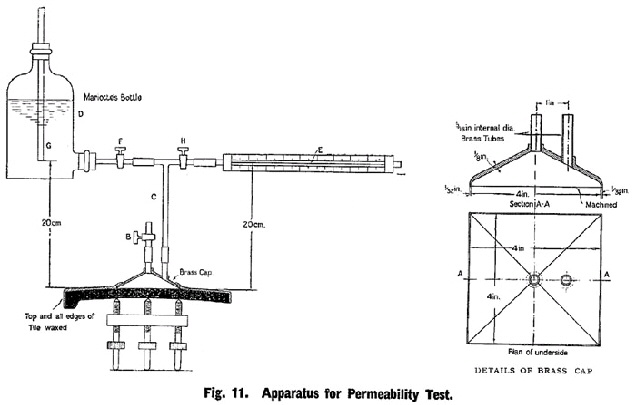
PERMEABILITY TEST. | ||||||||||||||||||||||||||||||
14. The average permeability of the tiles, when determined by the method described in Appendix B, shall be such that, at the end of 24 hours, the amount of water flowing through the tiles shall not exceed that indicated by a rate of flow of 1 in. per minute along a capillary tube of 1 mm. bore, the surface area of tile exposed to water pressure being 16 sq. in. and the pressure-head (vertical height between surface of tile and centre of capillary tube) 20 cm. | ||||||||||||||||||||||||||||||
TILE FITTINGS. | ||||||||||||||||||||||||||||||
GENERAL. | ||||||||||||||||||||||||||||||
15. Eaves, tops, tile-and-a-half tiles, hips, valleys and angles shall conform to the standard quality for plain tiles and shall be of the same colour, surface and camber to match the tiles with which they are to be laid. | ||||||||||||||||||||||||||||||
Note.—While each pitch of roofing calls for its own particular pitch and shape of hip and valley tile, it is found in practice that one hip or valley tile can be used for two different pitches within the limits given in the Tables in Clause 16. | ||||||||||||||||||||||||||||||
DIMENSIONS. | ||||||||||||||||||||||||||||||
16. Dimensions given below are applicable to fittings for standard tiles of size 10½ in. x 6½ in. | ||||||||||||||||||||||||||||||
The letters mentioned below refer to the lettering shown on the diagrams. | ||||||||||||||||||||||||||||||
(a) eaves tiles and top course tiles shall be 6½ in. wide and 7½ in. long with a plus variation not exceeding 1/8 in. on the width and length. They shall have two nail holes in addition to two nibs or one continuous nib. | ||||||||||||||||||||||||||||||
(b) tile-and-a-half tiles shall be 9¾ in. wide and 10½ in. long with a plus variation not exceeding 1/8 in. on the length and width. They shall have three nail holes in addition to three nibs or one continuous nib. | ||||||||||||||||||||||||||||||
(c) hip tiles. | ||||||||||||||||||||||||||||||
(i) All pattern hip tiles. The sides AF and CD shall be parallel to the uncut edges of the abutting plain tiles, with a tolerance of ¼ in. | ||||||||||||||||||||||||||||||
The nail hole (C) shall be not less than ¼ in. nor more than 3/8 in. diameter. | ||||||||||||||||||||||||||||||
(ii) Angular hip tiles. The lower edges FE and ED shall, when laid, be horizontal and carry the lines of adjacent courses of plain tiles with a variation not exceeding ¼ in. either way (see Fig. 3). | ||||||||||||||||||||||||||||||
(iii) Round pattern hip tiles shall follow on similar lines to angular hip tiles except that on plan the lines. FE and ED shall be rounded about E2 and on section shall be rounded about Y2 (see Fig. 4). | ||||||||||||||||||||||||||||||
(iv) Angular and round pattern hip tiles shall be of such shapes that, when laid, they shall lie reasonably well in the same planes as those of the adjoining courses of plain tiles on each side and fit reasonably well on the hip tile below (see Figs. 3 and 4). | ||||||||||||||||||||||||||||||
(v) Constants and variants for all pattern hip tiles. | ||||||||||||||||||||||||||||||
| ||||||||||||||||||||||||||||||
(vi) Variants for angular and round pattern but not bonnet hip tiles. | ||||||||||||||||||||||||||||||
| ||||||||||||||||||||||||||||||
Note.—Measurements in this and the subsequent Table, particularly of dihedral and angles other than 90°, have been based on tiles of ½ in. thickness and with a camber of ¼ in. Makers of thicker tiles or tiles with a greater camber may need to vary thesemeasurements slightly so as to get the best appearance on the finished roof. | ||||||||||||||||||||||||||||||
(vii) Bonnet hip tiles will have a smaller dihedral angle than that of angular hip tiles for the same pitch of roof and will not fit down on to the hip tile below but will allow room for bedding to fill up the space between one hip tile and the next. As a consequence of the smaller dihedral angle bonnet hip tiles will not lie in the same planes as the adjoining plain tiles on each side (see Fig. 5). | ||||||||||||||||||||||||||||||
(d) VALLEY TILES. | ||||||||||||||||||||||||||||||
(i) Valley tiles shall be of such a shape that when laid they shall lie reasonably well in the same planes as those of the adjoining courses of plain tiles on each side and fit reasonably well on the valley tile below (see Fig. 6). | ||||||||||||||||||||||||||||||
The sides AF and CD shall be parallel to the uncut edges of the abutting plain tiles with a tolerance of ¼ in. | ||||||||||||||||||||||||||||||
The line BE shall be the centre-line of the valley where the two sides meet. | ||||||||||||||||||||||||||||||
The point Dp shall be 3¼ in. from O and not less than 1 in. from D2 nor less than 2 in. from D3. | ||||||||||||||||||||||||||||||
The point Fp shall be placed in a similar position along the line from F2 to F3 in relation to point R. | ||||||||||||||||||||||||||||||
These points Dp and Fp must not be less than 11½ in. measured in straight lines from B. | ||||||||||||||||||||||||||||||
The points D and F may be joined by a curved line provided that it does not pass inside the straight lines joining D to D3 D3 to D2 D2 to E, E to F2 F2 to F3 and F3 to F. | ||||||||||||||||||||||||||||||
| ||||||||||||||||||||||||||||||
Permissible variations. | ||||||||||||||||||||||||||||||
The lengths AF and CD each shall be not less than 9½ in. | ||||||||||||||||||||||||||||||
The lengths AB and BC each may vary from 3/8 in. to 1½ in. | ||||||||||||||||||||||||||||||
Variants. | ||||||||||||||||||||||||||||||
| ||||||||||||||||||||||||||||||
(iii) Rounded valley tiles. These shall be on similar lines to angular valley tiles, except that the angle FYD will be rounded about Y2. | ||||||||||||||||||||||||||||||
(e) RIDGES | ||||||||||||||||||||||||||||||
(i) General. Ridges may be either 12 in. or 18 in. long with a plus or minus tolerance of ½ in. | ||||||||||||||||||||||||||||||
The thickness shall be not less than 5/8 in. and they shall be true in shape, free from warping and other defects. | ||||||||||||||||||||||||||||||
These ridges may all have capped joints, but the effective covering capacity for length shall remain as 12 in. or 18 in. as for butt jointed ridges. | ||||||||||||||||||||||||||||||
(ii) Angle ridges. Plain. Each wing shall be not less than 5½ in. wide measured internally X to Y and Y to Z (see Fig. 7). | ||||||||||||||||||||||||||||||
(iii) Half-round ridges shall be not less than 7¾ in. internal diameter X to Z (see Fig. 8). | ||||||||||||||||||||||||||||||
(iv) Segmental ridges shall be of such a diameter that the chord of half the arc XYZ shall be not less than 4½ in. (see Fig. 9). | ||||||||||||||||||||||||||||||
(v) Hog back ridges shall have an internal girth of not less than 11½ in. (XYZ) (see Fig. 10). | ||||||||||||||||||||||||||||||
APPENDIX A. | ||||||||||||||||||||||||||||||
Method of Carrying Out Transverse Test. | ||||||||||||||||||||||||||||||
Twelve tiles shall be selected in the manner described in Clause 12. | ||||||||||||||||||||||||||||||
(a) Wet. Six tiles shall be immersed in water at a temperature of 60°F. (16°C.) to 68°F. (20°C.) for 24 hours and immediately tested wet in the following manner : | ||||||||||||||||||||||||||||||
Each tile to be tested shall be evenly supported upon two self-aligning steel bearers not less than ¾ in. diameter, the distance between the centres of the bearers being 7½ in. | ||||||||||||||||||||||||||||||
The load shall then be applied centrally at a uniform rate of 100 to 150 lb. per minute through a third steel bearer also not less than ¾ in. diameter, placed midway between the supports upon the upper surface of the tile and parallel to the supports. The length of all bearers shall exceed the maximum width of the tile to be tested. | ||||||||||||||||||||||||||||||
A suitable form of apparatus is described in Appendix C for information. | ||||||||||||||||||||||||||||||
The average breaking load of the six tiles shall be taken. | ||||||||||||||||||||||||||||||
(b) Dry. Six tiles shall be dried at a temperature of approximately 194°F. (90°C.) to 212°F. (100 °C.) to a constant weight, and tested in the same manner as for the wet test described above. | ||||||||||||||||||||||||||||||
APPENDIX B. | ||||||||||||||||||||||||||||||
Method of Carrying Out Permeability Test. | ||||||||||||||||||||||||||||||
Three tiles, selected in the manner described in Clause 12, shall be tested in the following manner : | ||||||||||||||||||||||||||||||
Each tile to be tested shall be placed horizontally, face uppermost, on three points, as shown in Fig. 11. The special metal cover A, shown in detail in Fig. 11, shall be placed centrally on the upper surface of the tile and attached thereto by Faraday Wax *, which shall cover the whole of the remaining upper surface of the tile and the four edges, so as to make a water-tight joint between the metal cover and the tile. | ||||||||||||||||||||||||||||||
The metal cover A is provided with air-cock B and tube connection C. | ||||||||||||||||||||||||||||||
* Faraday Wax is a mixture of resin, beeswax and red oxide, and can be obtained from the usual suppliers of chemical stores. | ||||||||||||||||||||||||||||||
The space enclosed by the metal cover A and the upper surface of the tile shall be connected through C to a reservoir of water D and to a calibrated capillary tube E. | ||||||||||||||||||||||||||||||
On commencing the test, cocks F and B shall be open to admit water to the metal cover A. When this is fully charged with water, cock B shall be closed. The water shall then be allowed to pass into the tile for 24 hours, during which time the level of water in the reservoir D shall be maintained if necessary by adding water, above level of the bottom of tube G. After 24 hours the tap H shall be opened and water allowed to fill the capillary tube E. Tap F shall then be closed and the rate of flow of water into or through the tile shall be deducted from the rate at which the water travels along the calibrated capillary tube E, a stop watch being used to measure the time. The flow of water through the tile shall not exceed that indicated in Clause 14. | ||||||||||||||||||||||||||||||
The average of the three tiles tested shall be taken. Should this test fail, a further three tiles shall be selected from the same batch, and the test repeated. If the average of the two tests complies with the limit laid down in Clause 14, the batch shall be considered to have passed the test. | ||||||||||||||||||||||||||||||
APPENDIX C. | ||||||||||||||||||||||||||||||
Description of Suitable Type of Testing Apparatus for Transverse Test. (See Figs. 12a and 12b.) | ||||||||||||||||||||||||||||||
The tile to be tested is placed on bearers A and B *. Bearer A is supported horizontally on two bearer screws C, which carry hardened steel balls D concentric with the bearer (see Fig. 12a). Bearer B is supported on one such bearer screw and ball. The load is applied through bearer E, also having one bearer screw and ball. The bearers A, B and E are of mild steel not less than ¾ in. in diameter and each is provided with two springs which hold the bearers in position. | ||||||||||||||||||||||||||||||
Bearer bar G carries link H which supports load-pan I. Link H is provided with stops J which, when the tile breaks, come into contact with frame K to prevent load-pan I from falling to the ground. Link H is guided in its vertical movement by guides L. | ||||||||||||||||||||||||||||||
M is a vessel containing shot, the flow of which through orifice N into load-pan I is controlled by swinging shutter O. Shutter O is provided with handle P and adjusting screw Q which, when the tile breaks, is struck by link H in falling thus automatically stopping the flow of shot from vessel M. Stop R limits the movement of shutter O and a fibre washer behind wing-nut S offers frictional resistance to easy movement of shutter O. | ||||||||||||||||||||||||||||||
* Self-aligning bearings are essential so that when the tile deflects under load the circular bearers rotate about their own axes and eliminate drag at the points of support | ||||||||||||||||||||||||||||||
The distance between the bearers A and B at the points of contact with the tile is 7½ in. Bearer E is midway between bearers A and B measured horizontally. | ||||||||||||||||||||||||||||||
Bearers A and B are in the same horizontal plane, parallel to each other and to bearer E. | ||||||||||||||||||||||||||||||
The tile to be tested is placed centrally on bearers A and B with its long axis at right angles to the bearers. Bearer E rests upon the upper surface of the tile. The load is applied gradually by adjusting lever P until the orifice in shutter O is opposite the orifice in vessel M, and screw Q is adjusted so that its point is clear of link H. The rate of flow of the shot must be between 100-150 lb. per minute. | ||||||||||||||||||||||||||||||
The breaking load includes bearer E, bearer bar G, link H, load-pan I and its contents. | ||||||||||||||||||||||||||||||
| ||||||||||||||||||||||||||||||
| ||||||||||||||||||||||||||||||
| ||||||||||||||||||||||||||||||
| ||||||||||||||||||||||||||||||
| ||||||||||||||||||||||||||||||
| ||||||||||||||||||||||||||||||
| ||||||||||||||||||||||||||||||
| ||||||||||||||||||||||||||||||
| ||||||||||||||||||||||||||||||
| ||||||||||||||||||||||||||||||
| ||||||||||||||||||||||||||||||
| ||||||||||||||||||||||||||||||
| ||||||||||||||||||||||||||||||
| ||||||||||||||||||||||||||||||
| ||||||||||||||||||||||||||||||
GIVEN under my Official Seal, | ||||||||||||||||||||||||||||||
this 23rd day of December, 1949. | ||||||||||||||||||||||||||||||
DANIEL MORRISSEY, | ||||||||||||||||||||||||||||||
Minister for Industry and Commerce. | ||||||||||||||||||||||||||||||