S.I. No. 340/1953 - Merchant Shipping (Radio) Rules, 1953.
S.I. No. 340 of 1953. | |||||||||||||||||||||||||||||||||||||||||||||||||||||||||||||||||||||||||||||||||||||||||||||||||||||||||||||||||||||||||||||||||||||||||||||||||||||||||||||||||||||||||||||
MERCHANT SHIPPING (RADIO) RULES, 1953. | |||||||||||||||||||||||||||||||||||||||||||||||||||||||||||||||||||||||||||||||||||||||||||||||||||||||||||||||||||||||||||||||||||||||||||||||||||||||||||||||||||||||||||||
ARRANGEMENT OF RULES. | |||||||||||||||||||||||||||||||||||||||||||||||||||||||||||||||||||||||||||||||||||||||||||||||||||||||||||||||||||||||||||||||||||||||||||||||||||||||||||||||||||||||||||||
PART 1. | |||||||||||||||||||||||||||||||||||||||||||||||||||||||||||||||||||||||||||||||||||||||||||||||||||||||||||||||||||||||||||||||||||||||||||||||||||||||||||||||||||||||||||||
GENERAL | |||||||||||||||||||||||||||||||||||||||||||||||||||||||||||||||||||||||||||||||||||||||||||||||||||||||||||||||||||||||||||||||||||||||||||||||||||||||||||||||||||||||||||||
| |||||||||||||||||||||||||||||||||||||||||||||||||||||||||||||||||||||||||||||||||||||||||||||||||||||||||||||||||||||||||||||||||||||||||||||||||||||||||||||||||||||||||||||
PART II. | |||||||||||||||||||||||||||||||||||||||||||||||||||||||||||||||||||||||||||||||||||||||||||||||||||||||||||||||||||||||||||||||||||||||||||||||||||||||||||||||||||||||||||||
RADIOTELEGRAPHY. | |||||||||||||||||||||||||||||||||||||||||||||||||||||||||||||||||||||||||||||||||||||||||||||||||||||||||||||||||||||||||||||||||||||||||||||||||||||||||||||||||||||||||||||
| |||||||||||||||||||||||||||||||||||||||||||||||||||||||||||||||||||||||||||||||||||||||||||||||||||||||||||||||||||||||||||||||||||||||||||||||||||||||||||||||||||||||||||||
PART III. | |||||||||||||||||||||||||||||||||||||||||||||||||||||||||||||||||||||||||||||||||||||||||||||||||||||||||||||||||||||||||||||||||||||||||||||||||||||||||||||||||||||||||||||
RADIOTELEPHONY. | |||||||||||||||||||||||||||||||||||||||||||||||||||||||||||||||||||||||||||||||||||||||||||||||||||||||||||||||||||||||||||||||||||||||||||||||||||||||||||||||||||||||||||||
| |||||||||||||||||||||||||||||||||||||||||||||||||||||||||||||||||||||||||||||||||||||||||||||||||||||||||||||||||||||||||||||||||||||||||||||||||||||||||||||||||||||||||||||
PART IV | |||||||||||||||||||||||||||||||||||||||||||||||||||||||||||||||||||||||||||||||||||||||||||||||||||||||||||||||||||||||||||||||||||||||||||||||||||||||||||||||||||||||||||||
TECHNICAL REQUIREMENTS OF RADIO EQUIPMENT FOR LIFEBOATS | |||||||||||||||||||||||||||||||||||||||||||||||||||||||||||||||||||||||||||||||||||||||||||||||||||||||||||||||||||||||||||||||||||||||||||||||||||||||||||||||||||||||||||||
| |||||||||||||||||||||||||||||||||||||||||||||||||||||||||||||||||||||||||||||||||||||||||||||||||||||||||||||||||||||||||||||||||||||||||||||||||||||||||||||||||||||||||||||
SCHEDULES. | |||||||||||||||||||||||||||||||||||||||||||||||||||||||||||||||||||||||||||||||||||||||||||||||||||||||||||||||||||||||||||||||||||||||||||||||||||||||||||||||||||||||||||||
| |||||||||||||||||||||||||||||||||||||||||||||||||||||||||||||||||||||||||||||||||||||||||||||||||||||||||||||||||||||||||||||||||||||||||||||||||||||||||||||||||||||||||||||
I, SEAN F. LEMASS, Minister for Industry and Commerce, after consultation with the Minister for Posts and Telegraphs and in exercise of the powers conferred upon me by section 15 of the Merchant Shipping (Safety Convention) Act, 1952 (No. 29 of 1952), hereby make the following Rules :— | |||||||||||||||||||||||||||||||||||||||||||||||||||||||||||||||||||||||||||||||||||||||||||||||||||||||||||||||||||||||||||||||||||||||||||||||||||||||||||||||||||||||||||||
|
PART I. GENERAL. | |||||||||||||||||||||||||||||||||||||||||||||||||||||||||||||||||||||||||||||||||||||||||||||||||||||||||||||||||||||||||||||||||||||||||||||||||||||||||||||||||||||||||||||
|
1 Interpretation, repeal and transitional provisions. | 1.—(1) These Rules may be cited as the Merchant Shipping (Radio) Rules, 1953. | ||||||||||||||||||||||||||||||||||||||||||||||||||||||||||||||||||||||||||||||||||||||||||||||||||||||||||||||||||||||||||||||||||||||||||||||||||||||||||||||||||||||||||||
(2) In these Rules— | |||||||||||||||||||||||||||||||||||||||||||||||||||||||||||||||||||||||||||||||||||||||||||||||||||||||||||||||||||||||||||||||||||||||||||||||||||||||||||||||||||||||||||||
" cargo ship " means a ship other than a passenger steamer ; | |||||||||||||||||||||||||||||||||||||||||||||||||||||||||||||||||||||||||||||||||||||||||||||||||||||||||||||||||||||||||||||||||||||||||||||||||||||||||||||||||||||||||||||
" connected " means electrically connected ; | |||||||||||||||||||||||||||||||||||||||||||||||||||||||||||||||||||||||||||||||||||||||||||||||||||||||||||||||||||||||||||||||||||||||||||||||||||||||||||||||||||||||||||||
" existing installation " means— | |||||||||||||||||||||||||||||||||||||||||||||||||||||||||||||||||||||||||||||||||||||||||||||||||||||||||||||||||||||||||||||||||||||||||||||||||||||||||||||||||||||||||||||
(a) an installation wholly installed before the date on which these Rules come into operation ; and | |||||||||||||||||||||||||||||||||||||||||||||||||||||||||||||||||||||||||||||||||||||||||||||||||||||||||||||||||||||||||||||||||||||||||||||||||||||||||||||||||||||||||||||
(b) an installation part of which was installed before the said date and the rest of which consists either of parts installed in replacement of identical parts, or parts which comply with the relative requirements of these Rules ; | |||||||||||||||||||||||||||||||||||||||||||||||||||||||||||||||||||||||||||||||||||||||||||||||||||||||||||||||||||||||||||||||||||||||||||||||||||||||||||||||||||||||||||||
" fishing boat " has the same meaning as in Section 370 of the Merchant Shipping Act, 1894 ; | |||||||||||||||||||||||||||||||||||||||||||||||||||||||||||||||||||||||||||||||||||||||||||||||||||||||||||||||||||||||||||||||||||||||||||||||||||||||||||||||||||||||||||||
" interference " in relation to any radio installation required by these Rules means the prejudicing by any emission or reflection of electro-magnetic energy of the fulfilment of the purposes of the installation ; | |||||||||||||||||||||||||||||||||||||||||||||||||||||||||||||||||||||||||||||||||||||||||||||||||||||||||||||||||||||||||||||||||||||||||||||||||||||||||||||||||||||||||||||
" mile " means a nautical mile of 6 080 feet ; | |||||||||||||||||||||||||||||||||||||||||||||||||||||||||||||||||||||||||||||||||||||||||||||||||||||||||||||||||||||||||||||||||||||||||||||||||||||||||||||||||||||||||||||
" Minister " means the Minister for Industry and Commerce ; | |||||||||||||||||||||||||||||||||||||||||||||||||||||||||||||||||||||||||||||||||||||||||||||||||||||||||||||||||||||||||||||||||||||||||||||||||||||||||||||||||||||||||||||
" operating position " in relation to any equipment means the position normally occupied by a person when operating that equipment ; | |||||||||||||||||||||||||||||||||||||||||||||||||||||||||||||||||||||||||||||||||||||||||||||||||||||||||||||||||||||||||||||||||||||||||||||||||||||||||||||||||||||||||||||
" radiotelegraph ship " means a ship, being a ship to which these Rules apply, which is provided with a radiotelegraph installation and which is not a radiotelephone ship ; | |||||||||||||||||||||||||||||||||||||||||||||||||||||||||||||||||||||||||||||||||||||||||||||||||||||||||||||||||||||||||||||||||||||||||||||||||||||||||||||||||||||||||||||
" radiotelephone distress frequency " means a frequency of 2182 kc/s. ; | |||||||||||||||||||||||||||||||||||||||||||||||||||||||||||||||||||||||||||||||||||||||||||||||||||||||||||||||||||||||||||||||||||||||||||||||||||||||||||||||||||||||||||||
" radiotelephone ship " means a cargo ship, being a ship to which these Rules apply, of not less than 500 tons but of less than 1,600 tons the owner of which has given the Minister notice in writing (which has not been withdrawn) that the ship is provided with a radiotelephone installation in compliance with these Rules ; | |||||||||||||||||||||||||||||||||||||||||||||||||||||||||||||||||||||||||||||||||||||||||||||||||||||||||||||||||||||||||||||||||||||||||||||||||||||||||||||||||||||||||||||
" radio watch " in the case of radiotelegraph ships, means listening on a frequency of 500 kc/s, and in the case of radiotelephone ships means listening on the radiotelephone distress frequency ; | |||||||||||||||||||||||||||||||||||||||||||||||||||||||||||||||||||||||||||||||||||||||||||||||||||||||||||||||||||||||||||||||||||||||||||||||||||||||||||||||||||||||||||||
" silence periods " means the periods of 3 minutes beginning for purposes of radiotelegraphy at 15 minutes and at 45 minutes after each hour, and for purposes of radiotelephony at each hour and at 30 minutes after each hour, in every case determined according to Greenwich Mean Time ; | |||||||||||||||||||||||||||||||||||||||||||||||||||||||||||||||||||||||||||||||||||||||||||||||||||||||||||||||||||||||||||||||||||||||||||||||||||||||||||||||||||||||||||||
" steamer " includes a ship propelled by electricity or other mechanical power ; | |||||||||||||||||||||||||||||||||||||||||||||||||||||||||||||||||||||||||||||||||||||||||||||||||||||||||||||||||||||||||||||||||||||||||||||||||||||||||||||||||||||||||||||
" tons " means gross tons ; | |||||||||||||||||||||||||||||||||||||||||||||||||||||||||||||||||||||||||||||||||||||||||||||||||||||||||||||||||||||||||||||||||||||||||||||||||||||||||||||||||||||||||||||
" Type A1 " refers to radiotelegraphy by the keying of a continuous wave on and off ; | |||||||||||||||||||||||||||||||||||||||||||||||||||||||||||||||||||||||||||||||||||||||||||||||||||||||||||||||||||||||||||||||||||||||||||||||||||||||||||||||||||||||||||||
" Type A2 " refers to amplitude modulated radiotelegraphy by the keying of a modulating audio-frequency or of an emission continuously modulated by an audio-frequency ; | |||||||||||||||||||||||||||||||||||||||||||||||||||||||||||||||||||||||||||||||||||||||||||||||||||||||||||||||||||||||||||||||||||||||||||||||||||||||||||||||||||||||||||||
" Type A3 " refers to double sideband amplitude modulated radiotelephony ; | |||||||||||||||||||||||||||||||||||||||||||||||||||||||||||||||||||||||||||||||||||||||||||||||||||||||||||||||||||||||||||||||||||||||||||||||||||||||||||||||||||||||||||||
" Type B waves " means damped waves ; | |||||||||||||||||||||||||||||||||||||||||||||||||||||||||||||||||||||||||||||||||||||||||||||||||||||||||||||||||||||||||||||||||||||||||||||||||||||||||||||||||||||||||||||
" wireless operator " means a person who, before the coming into operation of these Rules, was a person qualified to be an operator within the meaning of the Merchant Shipping (Wireless Telegraphy) Rules, 1939 ( S. R. & O. No. 318 of 1939 ). | |||||||||||||||||||||||||||||||||||||||||||||||||||||||||||||||||||||||||||||||||||||||||||||||||||||||||||||||||||||||||||||||||||||||||||||||||||||||||||||||||||||||||||||
(3) The Merchant Shipping (Wireless Telegraphy) Rules, 1939, are hereby revoked, except in so far as they relate to direction-finding apparatus. | |||||||||||||||||||||||||||||||||||||||||||||||||||||||||||||||||||||||||||||||||||||||||||||||||||||||||||||||||||||||||||||||||||||||||||||||||||||||||||||||||||||||||||||
(4) The provisions of the First Schedule to these Rules shall have effect for the purpose of the transition from the law in force before these Rules come into operation to the provisions of these rules. | |||||||||||||||||||||||||||||||||||||||||||||||||||||||||||||||||||||||||||||||||||||||||||||||||||||||||||||||||||||||||||||||||||||||||||||||||||||||||||||||||||||||||||||
(5) These Rules shall come into operation on the 19th day of November, 1953. | |||||||||||||||||||||||||||||||||||||||||||||||||||||||||||||||||||||||||||||||||||||||||||||||||||||||||||||||||||||||||||||||||||||||||||||||||||||||||||||||||||||||||||||
|
2 Application and Classification of Ships. | 2.—(1) These Rules shall apply to ships which are | ||||||||||||||||||||||||||||||||||||||||||||||||||||||||||||||||||||||||||||||||||||||||||||||||||||||||||||||||||||||||||||||||||||||||||||||||||||||||||||||||||||||||||||
(a) sea-going ships registered in the State ; | |||||||||||||||||||||||||||||||||||||||||||||||||||||||||||||||||||||||||||||||||||||||||||||||||||||||||||||||||||||||||||||||||||||||||||||||||||||||||||||||||||||||||||||
(b) other sea-going ships while they are within any port in the State ; | |||||||||||||||||||||||||||||||||||||||||||||||||||||||||||||||||||||||||||||||||||||||||||||||||||||||||||||||||||||||||||||||||||||||||||||||||||||||||||||||||||||||||||||
and are not | |||||||||||||||||||||||||||||||||||||||||||||||||||||||||||||||||||||||||||||||||||||||||||||||||||||||||||||||||||||||||||||||||||||||||||||||||||||||||||||||||||||||||||||
(i) troopships not registered in the State ; | |||||||||||||||||||||||||||||||||||||||||||||||||||||||||||||||||||||||||||||||||||||||||||||||||||||||||||||||||||||||||||||||||||||||||||||||||||||||||||||||||||||||||||||
(ii) ships not propelled by mechanical means ; | |||||||||||||||||||||||||||||||||||||||||||||||||||||||||||||||||||||||||||||||||||||||||||||||||||||||||||||||||||||||||||||||||||||||||||||||||||||||||||||||||||||||||||||
(iii) pleasure yachts ; | |||||||||||||||||||||||||||||||||||||||||||||||||||||||||||||||||||||||||||||||||||||||||||||||||||||||||||||||||||||||||||||||||||||||||||||||||||||||||||||||||||||||||||||
(iv) fishing boats, or | |||||||||||||||||||||||||||||||||||||||||||||||||||||||||||||||||||||||||||||||||||||||||||||||||||||||||||||||||||||||||||||||||||||||||||||||||||||||||||||||||||||||||||||
(v) cargo ships of less than 500 tons. | |||||||||||||||||||||||||||||||||||||||||||||||||||||||||||||||||||||||||||||||||||||||||||||||||||||||||||||||||||||||||||||||||||||||||||||||||||||||||||||||||||||||||||||
(2) The ships to which these Rules apply shall be classified as follows :— | |||||||||||||||||||||||||||||||||||||||||||||||||||||||||||||||||||||||||||||||||||||||||||||||||||||||||||||||||||||||||||||||||||||||||||||||||||||||||||||||||||||||||||||
Class I—Steamers carrying more than 250 passengers or in respect of which there is in force a certificate issued by the Minister, or by any authority empowered in that behalf by the laws of any country other than the State, to the effect that they are fit to carry more than 250 passengers, and which | |||||||||||||||||||||||||||||||||||||||||||||||||||||||||||||||||||||||||||||||||||||||||||||||||||||||||||||||||||||||||||||||||||||||||||||||||||||||||||||||||||||||||||||
(a) in the case of ships registered in the State are at sea for more than 16 hours between two consecutive ports ; | |||||||||||||||||||||||||||||||||||||||||||||||||||||||||||||||||||||||||||||||||||||||||||||||||||||||||||||||||||||||||||||||||||||||||||||||||||||||||||||||||||||||||||||
(b) in the case of ships other than ships registered in the State arrive at a port in the State having been at sea for more than 16 hours since last leaving port, or in respect of which clearance or transire is sought from a port in the State for a voyage requiring more than 16 hours at sea before reaching port. | |||||||||||||||||||||||||||||||||||||||||||||||||||||||||||||||||||||||||||||||||||||||||||||||||||||||||||||||||||||||||||||||||||||||||||||||||||||||||||||||||||||||||||||
Class II—(a) Passenger steamers other than those of Class I | |||||||||||||||||||||||||||||||||||||||||||||||||||||||||||||||||||||||||||||||||||||||||||||||||||||||||||||||||||||||||||||||||||||||||||||||||||||||||||||||||||||||||||||
(b) Cargo ships of 1,600 tons and upwards. | |||||||||||||||||||||||||||||||||||||||||||||||||||||||||||||||||||||||||||||||||||||||||||||||||||||||||||||||||||||||||||||||||||||||||||||||||||||||||||||||||||||||||||||
Class III—Cargo ships of 500 tons and upwards but of less than 1,600 tons. | |||||||||||||||||||||||||||||||||||||||||||||||||||||||||||||||||||||||||||||||||||||||||||||||||||||||||||||||||||||||||||||||||||||||||||||||||||||||||||||||||||||||||||||
|
3 Provision of Radio Installations. | 3.—(1) Every ship of Class I and Class II shall be provided with a radiotelegraph installation which shall include the equipment specified in the Second Schedule to these Rules. | ||||||||||||||||||||||||||||||||||||||||||||||||||||||||||||||||||||||||||||||||||||||||||||||||||||||||||||||||||||||||||||||||||||||||||||||||||||||||||||||||||||||||||||
(2) Every ship of Class III shall be provided with a radiotelephone installation which shall include the equipment specified in the Third Schedule to these Rules, or with a radiotelegraph installation which shall include the equipment specified in the Second Schedule to these Rules. Provided that the main and emergency radiotelegraph transmitters in a ship of Class III may be combined in a single instrument, if that instrument is capable of complying with the requirements of Parts I and III of the said Second Schedule. | |||||||||||||||||||||||||||||||||||||||||||||||||||||||||||||||||||||||||||||||||||||||||||||||||||||||||||||||||||||||||||||||||||||||||||||||||||||||||||||||||||||||||||||
|
4 Climatic and Durability Tests. | 4.—(1) All equipment the requirements for which are specified in these Rules shall be such that it will be free of mechanical defects and comply with the said requirements— | ||||||||||||||||||||||||||||||||||||||||||||||||||||||||||||||||||||||||||||||||||||||||||||||||||||||||||||||||||||||||||||||||||||||||||||||||||||||||||||||||||||||||||||
(a) while undergoing the vibration, dry heat, and low temperature tests specified in the Fourth Schedule to these Rules ; | |||||||||||||||||||||||||||||||||||||||||||||||||||||||||||||||||||||||||||||||||||||||||||||||||||||||||||||||||||||||||||||||||||||||||||||||||||||||||||||||||||||||||||||
(b) when subjected to the damp heat test specified in sub-paragraph (4) of paragraph 3 of the said Schedule ; and | |||||||||||||||||||||||||||||||||||||||||||||||||||||||||||||||||||||||||||||||||||||||||||||||||||||||||||||||||||||||||||||||||||||||||||||||||||||||||||||||||||||||||||||
(c) immediately after undergoing such of the other tests specified in the said Schedule as are applicable to the equipment in the circumstances. | |||||||||||||||||||||||||||||||||||||||||||||||||||||||||||||||||||||||||||||||||||||||||||||||||||||||||||||||||||||||||||||||||||||||||||||||||||||||||||||||||||||||||||||
(2) Any such equipment which is intended for use in the open or in an open boat shall be such that after undergoing the mould growth test specified in the Fourth Schedule to these Rules no mould growth will be present on it. | |||||||||||||||||||||||||||||||||||||||||||||||||||||||||||||||||||||||||||||||||||||||||||||||||||||||||||||||||||||||||||||||||||||||||||||||||||||||||||||||||||||||||||||
|
5 Interference with Reception. | 5. At no time while the ship is at sea shall the interference or mechanical noise produced by the radio installation required by these Rules or by other equipment in the ship be sufficient to prevent the effective reception of radio signals by means of such installation. | ||||||||||||||||||||||||||||||||||||||||||||||||||||||||||||||||||||||||||||||||||||||||||||||||||||||||||||||||||||||||||||||||||||||||||||||||||||||||||||||||||||||||||||
|
6 High Voltage Parts. | 6.—(1) All parts and wiring to which this Rule applies shall be protected from accidental access and, except in the case of a generator or converter, shall be isolated automatically from all sources of electrical energy when the means of protection are removed. Any such parts which are capacitors in a transmitter shall be capable of being discharged. | ||||||||||||||||||||||||||||||||||||||||||||||||||||||||||||||||||||||||||||||||||||||||||||||||||||||||||||||||||||||||||||||||||||||||||||||||||||||||||||||||||||||||||||
(2) This Rule applies to all parts and wiring of the equipment specified in these Rules in which the direct and alternating voltages (other than radio-frequency voltages) combine at any time to give an instantaneous voltage greater than— | |||||||||||||||||||||||||||||||||||||||||||||||||||||||||||||||||||||||||||||||||||||||||||||||||||||||||||||||||||||||||||||||||||||||||||||||||||||||||||||||||||||||||||||
(a) 50 volts in the case of equipment specified in the Fifth Schedule to these Rules ; | |||||||||||||||||||||||||||||||||||||||||||||||||||||||||||||||||||||||||||||||||||||||||||||||||||||||||||||||||||||||||||||||||||||||||||||||||||||||||||||||||||||||||||||
(b) 250 volts in the case of all other equipment. | |||||||||||||||||||||||||||||||||||||||||||||||||||||||||||||||||||||||||||||||||||||||||||||||||||||||||||||||||||||||||||||||||||||||||||||||||||||||||||||||||||||||||||||
|
7 Charging of Batteries. | 7. Means shall be provided on board every ship to which these Rules apply for the charging from the ship's main source of electrical energy of any batteries which are provided as a source of electrical energy for any part of the equipment required by these Rules. An alternative means of charging such batteries shall also be provided if the means of charging such batteries is a rotary converter. | ||||||||||||||||||||||||||||||||||||||||||||||||||||||||||||||||||||||||||||||||||||||||||||||||||||||||||||||||||||||||||||||||||||||||||||||||||||||||||||||||||||||||||||
|
PART II. RADIOTELEGRAPHY. | |||||||||||||||||||||||||||||||||||||||||||||||||||||||||||||||||||||||||||||||||||||||||||||||||||||||||||||||||||||||||||||||||||||||||||||||||||||||||||||||||||||||||||||
|
8 Electrical Independence of Main and Emergency Radiotelegraph Equipments. | 8. Subject to the provisions of paragraph (2) of Rule 3 of these Rules, the main and emergency radiotelegraph equipments provided on board a radiotelegraph ship shall be electrically independent of each other. | ||||||||||||||||||||||||||||||||||||||||||||||||||||||||||||||||||||||||||||||||||||||||||||||||||||||||||||||||||||||||||||||||||||||||||||||||||||||||||||||||||||||||||||
|
9 Radiotelegraph Room | 9.—(1) Every radiotelegraph installation provided on board a radiotelegraph ship shall be installed in one or more radiotelegraph rooms not used for any purpose other than the operation of radio equipment. The radiotelegraph rooms shall be in such a position that there will be no disturbance by extraneous noises or otherwise with the effective reception of radio signals, and shall be as high as practicable in the ship. | ||||||||||||||||||||||||||||||||||||||||||||||||||||||||||||||||||||||||||||||||||||||||||||||||||||||||||||||||||||||||||||||||||||||||||||||||||||||||||||||||||||||||||||
(2) Every radiotelegraph installation provided on board a radiotelegraph ship shall be installed in such a position that it will be protected against disturbance of its effectiveness by water or by extremes of temperature. | |||||||||||||||||||||||||||||||||||||||||||||||||||||||||||||||||||||||||||||||||||||||||||||||||||||||||||||||||||||||||||||||||||||||||||||||||||||||||||||||||||||||||||||
(3) Every radiotelegraph room shall be provided with— | |||||||||||||||||||||||||||||||||||||||||||||||||||||||||||||||||||||||||||||||||||||||||||||||||||||||||||||||||||||||||||||||||||||||||||||||||||||||||||||||||||||||||||||
(a) an efficient two-way means of calling and voice communication with the bridge and any other place from which the ship is normally navigated. Such means of communication shall be a voicepipe or a telephone, or some other means equally efficient, and shall be independent of the main communication system of the ship and of the ship's main source of electrical energy ; | |||||||||||||||||||||||||||||||||||||||||||||||||||||||||||||||||||||||||||||||||||||||||||||||||||||||||||||||||||||||||||||||||||||||||||||||||||||||||||||||||||||||||||||
(b) a reliable clock, equipped with a dial not less than 5 inches in diameter and a centre seconds hand, securely mounted in such a position that the entire dial can be easily and accurately observed from the radiotelegraph operating position and, if the ship is provided with an autoalarm, from the position normally occupied by a person testing the autoalarm ; | |||||||||||||||||||||||||||||||||||||||||||||||||||||||||||||||||||||||||||||||||||||||||||||||||||||||||||||||||||||||||||||||||||||||||||||||||||||||||||||||||||||||||||||
(c) an electric lamp, operated from the source of electrical energy required by paragraph (2) of Rule 12 of these Rules and permanently arranged so as to be capable of providing adequate illumination of the operating controls of the main and emergency radiotelegraph installations and of the clock required by this Rule, and controlled by two-way switches placed respectively near the entrance to the radiotelegraph room and at the radiotelegraph operating position ; | |||||||||||||||||||||||||||||||||||||||||||||||||||||||||||||||||||||||||||||||||||||||||||||||||||||||||||||||||||||||||||||||||||||||||||||||||||||||||||||||||||||||||||||
(d) an additional electric lamp, for use as an inspection lamp, operated from the aforesaid source of energy, and provided with a flexible lead of sufficient length to enable all parts of the radiotelegraph installation to be easily seen ; | |||||||||||||||||||||||||||||||||||||||||||||||||||||||||||||||||||||||||||||||||||||||||||||||||||||||||||||||||||||||||||||||||||||||||||||||||||||||||||||||||||||||||||||
(e) a chair capable of being fixed at the radiotelegraph operating position. | |||||||||||||||||||||||||||||||||||||||||||||||||||||||||||||||||||||||||||||||||||||||||||||||||||||||||||||||||||||||||||||||||||||||||||||||||||||||||||||||||||||||||||||
(4) A complete list of spare equipment and spare parts carried on board the ship for the maintenance of the radiotelegraph installation, shall be available in every radiotelegraph room and shall indicate where such equipment and parts are kept. | |||||||||||||||||||||||||||||||||||||||||||||||||||||||||||||||||||||||||||||||||||||||||||||||||||||||||||||||||||||||||||||||||||||||||||||||||||||||||||||||||||||||||||||
(5) A calibration table or calibration curve for each transmitter and receiver forming part of the radiotelegraph installation shall always be available in a radiotelegraph room, unless the transmitter or receiver, as the case may be, is directly calibrated. | |||||||||||||||||||||||||||||||||||||||||||||||||||||||||||||||||||||||||||||||||||||||||||||||||||||||||||||||||||||||||||||||||||||||||||||||||||||||||||||||||||||||||||||
(6) In the case of a radiotelegraph installation which is not an existing installation, a complete diagram of the wiring of such installation shall always be available in a radiotelegraph room. | |||||||||||||||||||||||||||||||||||||||||||||||||||||||||||||||||||||||||||||||||||||||||||||||||||||||||||||||||||||||||||||||||||||||||||||||||||||||||||||||||||||||||||||
|
10 Aerials | 10.—(1) Every radiotelegraph ship shall be fitted with a main aerial and an emergency aerial ; provided that the Minister may exempt any ship from the requirement of an emergency aerial if he is satisfiedthat the fitting of such an aerial is impracticable or unreasonable in the circumstances. Any ship so exempted shall carry a spare aerial completely assembled for immediate erection. | ||||||||||||||||||||||||||||||||||||||||||||||||||||||||||||||||||||||||||||||||||||||||||||||||||||||||||||||||||||||||||||||||||||||||||||||||||||||||||||||||||||||||||||
(2) Each of the halyards used for supporting such main aerial shall be fitted with a safety loop between the masthead or other aerial support and an aerial insulator. Such safety loop shall consist of a part of the halyard not less than three feet long, the loop being closed by a link not more than one foot three inches long with a breaking load not more than one-third of the breaking load of the aerial or the halyard, whichever is the less. | |||||||||||||||||||||||||||||||||||||||||||||||||||||||||||||||||||||||||||||||||||||||||||||||||||||||||||||||||||||||||||||||||||||||||||||||||||||||||||||||||||||||||||||
(3) A rigging plan of such aerials shall be available in a radiotelegraph room, and shall show the following :— | |||||||||||||||||||||||||||||||||||||||||||||||||||||||||||||||||||||||||||||||||||||||||||||||||||||||||||||||||||||||||||||||||||||||||||||||||||||||||||||||||||||||||||||
(a) elevation and plan views of the aerials ; | |||||||||||||||||||||||||||||||||||||||||||||||||||||||||||||||||||||||||||||||||||||||||||||||||||||||||||||||||||||||||||||||||||||||||||||||||||||||||||||||||||||||||||||
(b) the measurements of the aerials in feet and inches ; and | |||||||||||||||||||||||||||||||||||||||||||||||||||||||||||||||||||||||||||||||||||||||||||||||||||||||||||||||||||||||||||||||||||||||||||||||||||||||||||||||||||||||||||||
(c) the height of the aerials in metres measured in the manner specified in paragraph (3) of Rule 11 of these Rules. | |||||||||||||||||||||||||||||||||||||||||||||||||||||||||||||||||||||||||||||||||||||||||||||||||||||||||||||||||||||||||||||||||||||||||||||||||||||||||||||||||||||||||||||
(4) The main aerial and the emergency aerial (if any) shall where practicable, be so rigged that damage to the one will not affect the efficiency of the other. | |||||||||||||||||||||||||||||||||||||||||||||||||||||||||||||||||||||||||||||||||||||||||||||||||||||||||||||||||||||||||||||||||||||||||||||||||||||||||||||||||||||||||||||
(5) The main and emergency aerials shall each be capable of being connected, as circumstances may require, to | |||||||||||||||||||||||||||||||||||||||||||||||||||||||||||||||||||||||||||||||||||||||||||||||||||||||||||||||||||||||||||||||||||||||||||||||||||||||||||||||||||||||||||||
(a) the main transmitter, either directly or with the intervention of an amplifier ; | |||||||||||||||||||||||||||||||||||||||||||||||||||||||||||||||||||||||||||||||||||||||||||||||||||||||||||||||||||||||||||||||||||||||||||||||||||||||||||||||||||||||||||||
(b) the main receiver ; and | |||||||||||||||||||||||||||||||||||||||||||||||||||||||||||||||||||||||||||||||||||||||||||||||||||||||||||||||||||||||||||||||||||||||||||||||||||||||||||||||||||||||||||||
(c) the emergency transmitter. | |||||||||||||||||||||||||||||||||||||||||||||||||||||||||||||||||||||||||||||||||||||||||||||||||||||||||||||||||||||||||||||||||||||||||||||||||||||||||||||||||||||||||||||
The emergency aerial shall also be capable of being connected to the emergency receiver. | |||||||||||||||||||||||||||||||||||||||||||||||||||||||||||||||||||||||||||||||||||||||||||||||||||||||||||||||||||||||||||||||||||||||||||||||||||||||||||||||||||||||||||||
|
11 Range of Transmitters | 11.—(1) The normal ranges of the radiotelegraph transmitters provided in accordance with the foregoing provisions of these Rules shall not be less than— | ||||||||||||||||||||||||||||||||||||||||||||||||||||||||||||||||||||||||||||||||||||||||||||||||||||||||||||||||||||||||||||||||||||||||||||||||||||||||||||||||||||||||||||
(a) in the case of a ship of Class I, 175 miles for the main transmitter and 150 miles for the emergency transmitter ; | |||||||||||||||||||||||||||||||||||||||||||||||||||||||||||||||||||||||||||||||||||||||||||||||||||||||||||||||||||||||||||||||||||||||||||||||||||||||||||||||||||||||||||||
(b) in the case of a ship of Class II, 150 miles for the main transmitter and 100 miles for the emergency transmitter ; | |||||||||||||||||||||||||||||||||||||||||||||||||||||||||||||||||||||||||||||||||||||||||||||||||||||||||||||||||||||||||||||||||||||||||||||||||||||||||||||||||||||||||||||
(c) in the case of a ship of Class III, 100 miles for the main transmitter and 75 miles for the emergency transmitter. | |||||||||||||||||||||||||||||||||||||||||||||||||||||||||||||||||||||||||||||||||||||||||||||||||||||||||||||||||||||||||||||||||||||||||||||||||||||||||||||||||||||||||||||
(2) The range of a transmitter for the purposes of these Rules shall be determined, at the option of the owner of the ship, either by reckoning or by test. | |||||||||||||||||||||||||||||||||||||||||||||||||||||||||||||||||||||||||||||||||||||||||||||||||||||||||||||||||||||||||||||||||||||||||||||||||||||||||||||||||||||||||||||
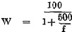
(3) For the purposes of these Rules the normal range of a radiotelegraph transmitter when determined by reckoning, shall be calculated by ascertaining the product of the root mean square current in amperes at the base of the main aerial and the maximum height in metres of the aerial measured from the load line mark indicating the greatest depth to which the ship may at any time or place besubmerged in accordance with the Merchant Shipping (Safety and Load Line Conventions) Act, 1933 (No. 42 of 1933), or if there is no such mark on the ship, from the mean level of the surface of the water in which the ship is afloat. The product so ascertained in metre-amperes shall be converted to miles in accordance with the following table :— | |||||||||||||||||||||||||||||||||||||||||||||||||||||||||||||||||||||||||||||||||||||||||||||||||||||||||||||||||||||||||||||||||||||||||||||||||||||||||||||||||||||||||||||
| |||||||||||||||||||||||||||||||||||||||||||||||||||||||||||||||||||||||||||||||||||||||||||||||||||||||||||||||||||||||||||||||||||||||||||||||||||||||||||||||||||||||||||||
(4) For the purposes of these Rules the normal range of a radiotelegraph transmitter, when determined by test, shall be the distance to which signals can be transmitted by such transmitter over the sea by day under normal conditions on a frequency of 500 kc/s so as to set up at the receiver a total root mean square field strength of at least 50 microvolts per metre. | |||||||||||||||||||||||||||||||||||||||||||||||||||||||||||||||||||||||||||||||||||||||||||||||||||||||||||||||||||||||||||||||||||||||||||||||||||||||||||||||||||||||||||||
|
12 Supply of electrical energy | 12.—(1) There shall be available in every radiotelegraph ship while the ship is at sea, and at all reasonable times when the ship is in port for testing purposes, a supply of electrical energy from the ship's main source of electrical energy sufficient for the operation of the main radiotelegraph equipment in accordance with these Rules, and for the charging of any batteries which are a source of electrical energy for the radiotelegraph installation. The rated voltage of the supply of electrical energy for the main equipment shall be maintained within plus or minus 10 per cent. The supply of electrical energy shall, if it is a direct current supply, be of correct polarity. Provided that in any ship not engaged on an international voyage the aforesaid supply of electrical energy may be derived from a battery, in which case a duplicate battery shall also be provided for that purpose. | ||||||||||||||||||||||||||||||||||||||||||||||||||||||||||||||||||||||||||||||||||||||||||||||||||||||||||||||||||||||||||||||||||||||||||||||||||||||||||||||||||||||||||||
(2) The emergency equipment shall include a source of electrical energy independent of the propelling power of the ship and of the rest of the ship's electrical installation, and capable of being brought into immediate operation by means of a switchboard situated in a radiotelegraph room or readily accessible therefrom. Any source of electrical energy provided in compliance with this paragraph shall be of such capacity and shall be maintained at all times when at sea in such condition as to be able to supply continuously for a period of 6 hours, whether or not it is in use for any other purpose, a total current equal to the sum of | |||||||||||||||||||||||||||||||||||||||||||||||||||||||||||||||||||||||||||||||||||||||||||||||||||||||||||||||||||||||||||||||||||||||||||||||||||||||||||||||||||||||||||||
(a) the current required to operate the emergency transmitter with the key up ; | |||||||||||||||||||||||||||||||||||||||||||||||||||||||||||||||||||||||||||||||||||||||||||||||||||||||||||||||||||||||||||||||||||||||||||||||||||||||||||||||||||||||||||||
(b) three-fifths of the difference between the current required to operate the emergency transmitter with the key down and the current required to operate it with the key up ; | |||||||||||||||||||||||||||||||||||||||||||||||||||||||||||||||||||||||||||||||||||||||||||||||||||||||||||||||||||||||||||||||||||||||||||||||||||||||||||||||||||||||||||||
(c) the current required to operate the emergency receiver ; and | |||||||||||||||||||||||||||||||||||||||||||||||||||||||||||||||||||||||||||||||||||||||||||||||||||||||||||||||||||||||||||||||||||||||||||||||||||||||||||||||||||||||||||||
(d) the current consumed by the electric lamp required by paragraph (3) (c) of Rule 9 of these Rules. | |||||||||||||||||||||||||||||||||||||||||||||||||||||||||||||||||||||||||||||||||||||||||||||||||||||||||||||||||||||||||||||||||||||||||||||||||||||||||||||||||||||||||||||
(3) The source of electrical energy provided under paragraph (2) of this Rule shall not be used at any time except for the operation of— | |||||||||||||||||||||||||||||||||||||||||||||||||||||||||||||||||||||||||||||||||||||||||||||||||||||||||||||||||||||||||||||||||||||||||||||||||||||||||||||||||||||||||||||
(a) the emergency transmitter and receiver : | |||||||||||||||||||||||||||||||||||||||||||||||||||||||||||||||||||||||||||||||||||||||||||||||||||||||||||||||||||||||||||||||||||||||||||||||||||||||||||||||||||||||||||||
(b) the lamps required by paragraph 3 (c) and (d) of Rule 9 of these Rules ; | |||||||||||||||||||||||||||||||||||||||||||||||||||||||||||||||||||||||||||||||||||||||||||||||||||||||||||||||||||||||||||||||||||||||||||||||||||||||||||||||||||||||||||||
(c) the automatic keying device ; | |||||||||||||||||||||||||||||||||||||||||||||||||||||||||||||||||||||||||||||||||||||||||||||||||||||||||||||||||||||||||||||||||||||||||||||||||||||||||||||||||||||||||||||
(d) an autoalarm ; | |||||||||||||||||||||||||||||||||||||||||||||||||||||||||||||||||||||||||||||||||||||||||||||||||||||||||||||||||||||||||||||||||||||||||||||||||||||||||||||||||||||||||||||
(e) a direction-finder. | |||||||||||||||||||||||||||||||||||||||||||||||||||||||||||||||||||||||||||||||||||||||||||||||||||||||||||||||||||||||||||||||||||||||||||||||||||||||||||||||||||||||||||||
|
13 Tools, Measuring Instruments, Spare Parts, etc. | 13. Every radiotelegraph ship shall be provided with the tools, measuring instruments, spare parts and other material specified in the Sixth Schedule to these Rules. | ||||||||||||||||||||||||||||||||||||||||||||||||||||||||||||||||||||||||||||||||||||||||||||||||||||||||||||||||||||||||||||||||||||||||||||||||||||||||||||||||||||||||||||
|
14 Exemption of Class III ships | 14. The Minister may exempt any ship of Class III from any of the requirements of the foregoing provisions of this Part of these Rules, subject to such conditions as he thinks fit. | ||||||||||||||||||||||||||||||||||||||||||||||||||||||||||||||||||||||||||||||||||||||||||||||||||||||||||||||||||||||||||||||||||||||||||||||||||||||||||||||||||||||||||||
|
15 Provision of Radio Officers | 15.—(1) Every radiotelegraph ship which upon proceeding to sea is not provided with an autoalarm complying with the requirements specified in the Seventh Schedule to these Rules shall be provided with radio officers as follows :— | ||||||||||||||||||||||||||||||||||||||||||||||||||||||||||||||||||||||||||||||||||||||||||||||||||||||||||||||||||||||||||||||||||||||||||||||||||||||||||||||||||||||||||||
Class I.—Three radio officers. | |||||||||||||||||||||||||||||||||||||||||||||||||||||||||||||||||||||||||||||||||||||||||||||||||||||||||||||||||||||||||||||||||||||||||||||||||||||||||||||||||||||||||||||
Class II.—Two radio officers if she is at sea for not more than 48 hours between consecutive ports, and three radio officers if she is at sea for more than 48 hours between consecutive ports. | |||||||||||||||||||||||||||||||||||||||||||||||||||||||||||||||||||||||||||||||||||||||||||||||||||||||||||||||||||||||||||||||||||||||||||||||||||||||||||||||||||||||||||||
Class III.—One radio officer. | |||||||||||||||||||||||||||||||||||||||||||||||||||||||||||||||||||||||||||||||||||||||||||||||||||||||||||||||||||||||||||||||||||||||||||||||||||||||||||||||||||||||||||||
(2) Every radiotelegraph ship which upon proceeding to sea is provided with an autoalarm complying with the aforesaid requirements shall be provided with radio officers as follows :— | |||||||||||||||||||||||||||||||||||||||||||||||||||||||||||||||||||||||||||||||||||||||||||||||||||||||||||||||||||||||||||||||||||||||||||||||||||||||||||||||||||||||||||||
Class I.—Two radio officers. | |||||||||||||||||||||||||||||||||||||||||||||||||||||||||||||||||||||||||||||||||||||||||||||||||||||||||||||||||||||||||||||||||||||||||||||||||||||||||||||||||||||||||||||
Class II.—One radio officer. | |||||||||||||||||||||||||||||||||||||||||||||||||||||||||||||||||||||||||||||||||||||||||||||||||||||||||||||||||||||||||||||||||||||||||||||||||||||||||||||||||||||||||||||
Class III.—One radio officer. | |||||||||||||||||||||||||||||||||||||||||||||||||||||||||||||||||||||||||||||||||||||||||||||||||||||||||||||||||||||||||||||||||||||||||||||||||||||||||||||||||||||||||||||
|
16 Qualifications of Radio Officers. | 16.—(1) For the purposes of these Rules no person shall be qualified to be a radio officer on board a ship registered in the State unless he holds a valid certificate of proficiency or competence in radiotelegraphy of the first or second class granted by the Minister for Posts and Telegraphs, or by an authority empowered in that behalf by the laws of Great Britain or any Commonwealth country, and recognised by the Minister for Posts and Telegraphs as the equivalent of such a certificate granted by him. In the case of one at least of the radio officers on board apassenger steamer registered in the State, such certificate shall be a certificate of the first class granted by the Minister for Posts and Telegraphs or a certificate granted by such an authority and recognised by the Minister for Posts and Telegraphs as the equivalent of a certificate of the first class granted by him. | ||||||||||||||||||||||||||||||||||||||||||||||||||||||||||||||||||||||||||||||||||||||||||||||||||||||||||||||||||||||||||||||||||||||||||||||||||||||||||||||||||||||||||||
(2) For the purposes of paragraph (1) of this Rule no certificate of proficiency or competence shall be deemed to be valid at any date if it was granted more than 2 years before that date and either | |||||||||||||||||||||||||||||||||||||||||||||||||||||||||||||||||||||||||||||||||||||||||||||||||||||||||||||||||||||||||||||||||||||||||||||||||||||||||||||||||||||||||||||
(a) the holder's periods of experience do not total three months, or | |||||||||||||||||||||||||||||||||||||||||||||||||||||||||||||||||||||||||||||||||||||||||||||||||||||||||||||||||||||||||||||||||||||||||||||||||||||||||||||||||||||||||||||
(b) the holder's last experience was more than 2 years before that date, | |||||||||||||||||||||||||||||||||||||||||||||||||||||||||||||||||||||||||||||||||||||||||||||||||||||||||||||||||||||||||||||||||||||||||||||||||||||||||||||||||||||||||||||
unless the holder satisfies the Minister for Posts and Telegraphs by re-examination or otherwise that he still possesses all of the qualifications described in his certificate. For the purposes of this paragraph the expression " experience " means experience at sea as a radio officer or wireless operator or experience as an operator of radiotelegraph apparatus at a radiotelegraph station maintained on land by the Minister for Posts and Telegraphs for communication with ships. | |||||||||||||||||||||||||||||||||||||||||||||||||||||||||||||||||||||||||||||||||||||||||||||||||||||||||||||||||||||||||||||||||||||||||||||||||||||||||||||||||||||||||||||
(3) At least one of the radio officers on board a ship of Class I or Class II registered in the State shall be a person who has had experience at sea as a radio officer or wireless operator for a total of not less than— | |||||||||||||||||||||||||||||||||||||||||||||||||||||||||||||||||||||||||||||||||||||||||||||||||||||||||||||||||||||||||||||||||||||||||||||||||||||||||||||||||||||||||||||
(a) two years in the case of ships of Class I ; | |||||||||||||||||||||||||||||||||||||||||||||||||||||||||||||||||||||||||||||||||||||||||||||||||||||||||||||||||||||||||||||||||||||||||||||||||||||||||||||||||||||||||||||
(b) one year in the case of ships of Class II (a) ; | |||||||||||||||||||||||||||||||||||||||||||||||||||||||||||||||||||||||||||||||||||||||||||||||||||||||||||||||||||||||||||||||||||||||||||||||||||||||||||||||||||||||||||||
(c) six months in the case of ships of Class II (b), being ships of 3,000 tons or upwards ; | |||||||||||||||||||||||||||||||||||||||||||||||||||||||||||||||||||||||||||||||||||||||||||||||||||||||||||||||||||||||||||||||||||||||||||||||||||||||||||||||||||||||||||||
(d) three months, in the case of ships of Class II (b), being ships of 1,600 tons and upwards but under 3,000 tons. | |||||||||||||||||||||||||||||||||||||||||||||||||||||||||||||||||||||||||||||||||||||||||||||||||||||||||||||||||||||||||||||||||||||||||||||||||||||||||||||||||||||||||||||
(4) For the purposes of these Rules no person shall be deemed to be a radio officer on board a ship not registered in the State unless he holds a valid certificate of proficiency or competence in radio-telegraphy granted by an authority empowered or recognised in that behalf by the laws of the country in which the ship is registered and recognised by the Minister for Posts and Telegraphs as the equivalent of such a certificate granted by him. | |||||||||||||||||||||||||||||||||||||||||||||||||||||||||||||||||||||||||||||||||||||||||||||||||||||||||||||||||||||||||||||||||||||||||||||||||||||||||||||||||||||||||||||
|
17 Radio Watch by Radiotelegraph. | 17.—(1) Subject to the provisions of paragraph (1) of Rule 18 radio watch shall be maintained at sea on board every radiotelegraph ship by a radio officer as follows :— | ||||||||||||||||||||||||||||||||||||||||||||||||||||||||||||||||||||||||||||||||||||||||||||||||||||||||||||||||||||||||||||||||||||||||||||||||||||||||||||||||||||||||||||
(a) if the ship upon proceeding to sea is not provided with an autoalarm complying with the requirements specified in the Seventh Schedule to these Rules :— | |||||||||||||||||||||||||||||||||||||||||||||||||||||||||||||||||||||||||||||||||||||||||||||||||||||||||||||||||||||||||||||||||||||||||||||||||||||||||||||||||||||||||||||
(i) in the case of a ship of Class I or Class II a continuous watch ; | |||||||||||||||||||||||||||||||||||||||||||||||||||||||||||||||||||||||||||||||||||||||||||||||||||||||||||||||||||||||||||||||||||||||||||||||||||||||||||||||||||||||||||||
(ii) in the case of a ship of Class III a watch of eight hours a day at the times specified in Column 5 of the Eighth Schedule to these Rules in relation to the zone in which the ship then is ; | |||||||||||||||||||||||||||||||||||||||||||||||||||||||||||||||||||||||||||||||||||||||||||||||||||||||||||||||||||||||||||||||||||||||||||||||||||||||||||||||||||||||||||||
(b) if the ship upon proceeding to sea is provided with an auto-alarm as aforesaid :— | |||||||||||||||||||||||||||||||||||||||||||||||||||||||||||||||||||||||||||||||||||||||||||||||||||||||||||||||||||||||||||||||||||||||||||||||||||||||||||||||||||||||||||||
(i) in the case of a ship of Class I a watch of sixteen hours a day at the times specified in Column 4 of the Eighth Schedule to these Rules in relation to the zone in which the ship then is ; | |||||||||||||||||||||||||||||||||||||||||||||||||||||||||||||||||||||||||||||||||||||||||||||||||||||||||||||||||||||||||||||||||||||||||||||||||||||||||||||||||||||||||||||
(ii) in the case of a ship of Class II or Class III a watch of eight hours a day at the times specified in Column 5 of the Eighth Schedule to these Rules in relation to the zone in which the ship then is. | |||||||||||||||||||||||||||||||||||||||||||||||||||||||||||||||||||||||||||||||||||||||||||||||||||||||||||||||||||||||||||||||||||||||||||||||||||||||||||||||||||||||||||||
(2) Any autoalarm provided on board a radiotelegraph ship shall be in operation at all times at which a radio watch is not maintained unless the autoalarm has broken down since the ship last put to sea and cannot be repaired at sea so as to operate effectively. | |||||||||||||||||||||||||||||||||||||||||||||||||||||||||||||||||||||||||||||||||||||||||||||||||||||||||||||||||||||||||||||||||||||||||||||||||||||||||||||||||||||||||||||
|
18 Watchkeeping, etc., by Radio Officers. | 18.—(1) Every radio officer on board a radiotelegraph ship shall keep radio watch by means of headphone reception throughout his period of duty except when another radio officer keeps radio watch by headphone reception. Provided that— | ||||||||||||||||||||||||||||||||||||||||||||||||||||||||||||||||||||||||||||||||||||||||||||||||||||||||||||||||||||||||||||||||||||||||||||||||||||||||||||||||||||||||||||
(a) radio watch may be maintained by means of loud-speaker reception, or | |||||||||||||||||||||||||||||||||||||||||||||||||||||||||||||||||||||||||||||||||||||||||||||||||||||||||||||||||||||||||||||||||||||||||||||||||||||||||||||||||||||||||||||
(b) if loud-speaker reception is impracticable radio watch may be dispensed with except during a silence period, | |||||||||||||||||||||||||||||||||||||||||||||||||||||||||||||||||||||||||||||||||||||||||||||||||||||||||||||||||||||||||||||||||||||||||||||||||||||||||||||||||||||||||||||
for such periods as may be necessary to enable the radio officer to perform other duties in compliance with these Rules or with the Merchant Shipping (Direction-Finders) Rules, 1953. | |||||||||||||||||||||||||||||||||||||||||||||||||||||||||||||||||||||||||||||||||||||||||||||||||||||||||||||||||||||||||||||||||||||||||||||||||||||||||||||||||||||||||||||
(2) Every radio officer on board a radiotelegraph ship provided with an autoalarm complying with the requirements specified in the Seventh Schedule to these Rules shall, whenever radio watch ceases to be maintained during or at the end of his period of duty, connect the autoalarm with the ship's main aerial, or with any other equally efficient aerial, and shall put the autoalarm into operation. Every radio officer who leaves an autoalarm in operation when he goes off duty shall before going off duty | |||||||||||||||||||||||||||||||||||||||||||||||||||||||||||||||||||||||||||||||||||||||||||||||||||||||||||||||||||||||||||||||||||||||||||||||||||||||||||||||||||||||||||||
(a) test the efficiency of the autoalarm : and | |||||||||||||||||||||||||||||||||||||||||||||||||||||||||||||||||||||||||||||||||||||||||||||||||||||||||||||||||||||||||||||||||||||||||||||||||||||||||||||||||||||||||||||
(b) immediately report the result of such test to the master of the ship or to the officer in charge of the navigation of the ship. | |||||||||||||||||||||||||||||||||||||||||||||||||||||||||||||||||||||||||||||||||||||||||||||||||||||||||||||||||||||||||||||||||||||||||||||||||||||||||||||||||||||||||||||
(3) Every such radio officer who finds an autoalarm connected to an aerial when he goes on duty shall immediately test the efficiency of the autoalarm before making any adjustment thereto. | |||||||||||||||||||||||||||||||||||||||||||||||||||||||||||||||||||||||||||||||||||||||||||||||||||||||||||||||||||||||||||||||||||||||||||||||||||||||||||||||||||||||||||||
(4) While a radiotelegraph ship is at sea, the radio officer, or if there is more than one, the first radio officer, shall cause the following tests to be made :— | |||||||||||||||||||||||||||||||||||||||||||||||||||||||||||||||||||||||||||||||||||||||||||||||||||||||||||||||||||||||||||||||||||||||||||||||||||||||||||||||||||||||||||||
(a) a test once a day of the emergency radiotelegraph transmitter connected with an artificial aerial complying with the requirements specified in paragraph 13 of Part III of the Second Schedule to these Rules ; | |||||||||||||||||||||||||||||||||||||||||||||||||||||||||||||||||||||||||||||||||||||||||||||||||||||||||||||||||||||||||||||||||||||||||||||||||||||||||||||||||||||||||||||
(b) if the ship is engaged on an international voyage a test once during every voyage of the emergency radiotelegraph transmitter connected with the emergency aerial, if any ; | |||||||||||||||||||||||||||||||||||||||||||||||||||||||||||||||||||||||||||||||||||||||||||||||||||||||||||||||||||||||||||||||||||||||||||||||||||||||||||||||||||||||||||||
(c) a test once a day by voltmeter and once a month by hydrometer of any batteries which are a source of energy for the radiotelegraph installation ; | |||||||||||||||||||||||||||||||||||||||||||||||||||||||||||||||||||||||||||||||||||||||||||||||||||||||||||||||||||||||||||||||||||||||||||||||||||||||||||||||||||||||||||||
(d) a test once a day of any other source of electrical energy provided for the emergency radiotelegraph equipment ; and | |||||||||||||||||||||||||||||||||||||||||||||||||||||||||||||||||||||||||||||||||||||||||||||||||||||||||||||||||||||||||||||||||||||||||||||||||||||||||||||||||||||||||||||
(e) a test once a day of the audible alarm circuits and of the bells forming part of the autoalarm. | |||||||||||||||||||||||||||||||||||||||||||||||||||||||||||||||||||||||||||||||||||||||||||||||||||||||||||||||||||||||||||||||||||||||||||||||||||||||||||||||||||||||||||||
(5) While a radiotelegraph ship is at sea, the radio officer, or if there is more than one, the first radio officer, shall take all steps within his power to cause the equipment referred to in these Rules to be properly maintained and when necessary to be repaired and adjusted. Such officer shall cause all batteries, being a source of electrical energy for any part of the radiotelegraph installation, which are found not to be fully charged to be brought up to that condition as soon as may be. | |||||||||||||||||||||||||||||||||||||||||||||||||||||||||||||||||||||||||||||||||||||||||||||||||||||||||||||||||||||||||||||||||||||||||||||||||||||||||||||||||||||||||||||
|
19 Restriction of Use of Emergency Transmitter. | 19. The transmitter forming part of the emergency radiotelegraph equipment shall not be used to transmit messages other than those relating to the safety of life at sea, unless such transmitter complies with the requirements specified in Part I of the Second Schedule to these Rules. | ||||||||||||||||||||||||||||||||||||||||||||||||||||||||||||||||||||||||||||||||||||||||||||||||||||||||||||||||||||||||||||||||||||||||||||||||||||||||||||||||||||||||||||
|
20 Radiotelegraph Log. | 20.—(1) A radiotelegraph log-book in the form specified in the Ninth Schedule hereto shall be kept in a radiotelegraph room on board every radiotelegraph ship registered in the State, and shall be available for inspection by any person authorised in that behalf by the Minister or by the Minister for Posts and Telegraphs. | ||||||||||||||||||||||||||||||||||||||||||||||||||||||||||||||||||||||||||||||||||||||||||||||||||||||||||||||||||||||||||||||||||||||||||||||||||||||||||||||||||||||||||||
(2) Every radio officer on board such a ship shall, when on duty, enter in such log-book:— | |||||||||||||||||||||||||||||||||||||||||||||||||||||||||||||||||||||||||||||||||||||||||||||||||||||||||||||||||||||||||||||||||||||||||||||||||||||||||||||||||||||||||||||
(a) his name ; | |||||||||||||||||||||||||||||||||||||||||||||||||||||||||||||||||||||||||||||||||||||||||||||||||||||||||||||||||||||||||||||||||||||||||||||||||||||||||||||||||||||||||||||
(b) the times at which he goes on and off duty ; | |||||||||||||||||||||||||||||||||||||||||||||||||||||||||||||||||||||||||||||||||||||||||||||||||||||||||||||||||||||||||||||||||||||||||||||||||||||||||||||||||||||||||||||
(c) the identifying number of each message transmitted by him, or received by him, together with the time and date of such transmission or reception, the station to which each message is transmitted by him and the station from which each message is received by him ; and | |||||||||||||||||||||||||||||||||||||||||||||||||||||||||||||||||||||||||||||||||||||||||||||||||||||||||||||||||||||||||||||||||||||||||||||||||||||||||||||||||||||||||||||
(d) a record of all incidents occurring during his period of duty which relates to the radiotelegraph installation and the operation thereof and which appear to him to be of importance to the safety of life at sea ; in particular, he shall make the following entries:— | |||||||||||||||||||||||||||||||||||||||||||||||||||||||||||||||||||||||||||||||||||||||||||||||||||||||||||||||||||||||||||||||||||||||||||||||||||||||||||||||||||||||||||||
(i) the full text of all messages transmitted by him or received by him which relate to immediate assistance required by persons in distress at sea or above the sea ; | |||||||||||||||||||||||||||||||||||||||||||||||||||||||||||||||||||||||||||||||||||||||||||||||||||||||||||||||||||||||||||||||||||||||||||||||||||||||||||||||||||||||||||||
(ii) the full text of all messages transmitted by him or received by him which are preceded by a signal in general international use as an urgency signal or a safety signal ; | |||||||||||||||||||||||||||||||||||||||||||||||||||||||||||||||||||||||||||||||||||||||||||||||||||||||||||||||||||||||||||||||||||||||||||||||||||||||||||||||||||||||||||||
(iii) a record of the radio watch maintained by him during each of the silence periods ; | |||||||||||||||||||||||||||||||||||||||||||||||||||||||||||||||||||||||||||||||||||||||||||||||||||||||||||||||||||||||||||||||||||||||||||||||||||||||||||||||||||||||||||||
(iv) a record of any incident occurring during his period of duty which affects the efficiency of the radiotelegraph installation ; | |||||||||||||||||||||||||||||||||||||||||||||||||||||||||||||||||||||||||||||||||||||||||||||||||||||||||||||||||||||||||||||||||||||||||||||||||||||||||||||||||||||||||||||
(v) a record of the tests conducted by him in accordance with paragraphs (2), (3) and (4) of Rule 18 of these Rules, and of the results of such tests ; | |||||||||||||||||||||||||||||||||||||||||||||||||||||||||||||||||||||||||||||||||||||||||||||||||||||||||||||||||||||||||||||||||||||||||||||||||||||||||||||||||||||||||||||
(vi) a record of the charging by him of any batteries used as a source of energy for the radiotelegraph installation ; and | |||||||||||||||||||||||||||||||||||||||||||||||||||||||||||||||||||||||||||||||||||||||||||||||||||||||||||||||||||||||||||||||||||||||||||||||||||||||||||||||||||||||||||||
(vii) if the ship is provided with an autoalarm, details of any failure or repair thereof during his period of duty. | |||||||||||||||||||||||||||||||||||||||||||||||||||||||||||||||||||||||||||||||||||||||||||||||||||||||||||||||||||||||||||||||||||||||||||||||||||||||||||||||||||||||||||||
(3) The radio officer, or if there is more than one, the first radio officer shall cause an entry to be made in such log-book at least once a day recording the time shown by the clock in each radiotelegraph room in comparison with Greenwich Mean Time, and any correction made in respect of that clock. | |||||||||||||||||||||||||||||||||||||||||||||||||||||||||||||||||||||||||||||||||||||||||||||||||||||||||||||||||||||||||||||||||||||||||||||||||||||||||||||||||||||||||||||
(4) The master of the ship and, if there is more than one radio officer, the first radio officer shall inspect and sign such log-book once a day. | |||||||||||||||||||||||||||||||||||||||||||||||||||||||||||||||||||||||||||||||||||||||||||||||||||||||||||||||||||||||||||||||||||||||||||||||||||||||||||||||||||||||||||||
(5) Section 242 of the Merchant Shipping Act, 1894 (which provides for the delivery of the official log-book to the Superintendent) and Section 256 of that Act (which provides among other things for the custody of the official log-book) shall apply to the radiotelegraph log-book as they apply to the official log-book. | |||||||||||||||||||||||||||||||||||||||||||||||||||||||||||||||||||||||||||||||||||||||||||||||||||||||||||||||||||||||||||||||||||||||||||||||||||||||||||||||||||||||||||||
|
PART III. RADIOTELEPHONY. | |||||||||||||||||||||||||||||||||||||||||||||||||||||||||||||||||||||||||||||||||||||||||||||||||||||||||||||||||||||||||||||||||||||||||||||||||||||||||||||||||||||||||||||
|
21 Aerial. | 21. Every radiotelephone ship shall be fitted with an aerial, and in addition shall carry a spare aerial completely assembled for immediate erection. A rigging plan of the fitted aerial shall be available on board and shall show— | ||||||||||||||||||||||||||||||||||||||||||||||||||||||||||||||||||||||||||||||||||||||||||||||||||||||||||||||||||||||||||||||||||||||||||||||||||||||||||||||||||||||||||||
(a) elevation and plan views of the aerial | |||||||||||||||||||||||||||||||||||||||||||||||||||||||||||||||||||||||||||||||||||||||||||||||||||||||||||||||||||||||||||||||||||||||||||||||||||||||||||||||||||||||||||||
(b) the measurements of the aerial in feet and inches ; and | |||||||||||||||||||||||||||||||||||||||||||||||||||||||||||||||||||||||||||||||||||||||||||||||||||||||||||||||||||||||||||||||||||||||||||||||||||||||||||||||||||||||||||||
(c) the height of the aerial in metres measured in the manner specified in paragraph (3) of Rule 22 of these Rules. | |||||||||||||||||||||||||||||||||||||||||||||||||||||||||||||||||||||||||||||||||||||||||||||||||||||||||||||||||||||||||||||||||||||||||||||||||||||||||||||||||||||||||||||
|
22 Range. | 22.—(1) The normal range of the radiotelephone transmitter provided in accordance with the foregoing provisions of these Rules shall not be less than 150 miles. | ||||||||||||||||||||||||||||||||||||||||||||||||||||||||||||||||||||||||||||||||||||||||||||||||||||||||||||||||||||||||||||||||||||||||||||||||||||||||||||||||||||||||||||
(2) The range of a radiotelephone transmitter for the purposes of these Rules shall be determined at the option of the Owner of the ship either by reckoning or by test. | |||||||||||||||||||||||||||||||||||||||||||||||||||||||||||||||||||||||||||||||||||||||||||||||||||||||||||||||||||||||||||||||||||||||||||||||||||||||||||||||||||||||||||||
(3) For the purposes of these Rules the normal range of a radiotelephone transmitter, when determined by reckoning on the radiotelephone distress frequency, shall be calculated by ascertaining the product of the root mean square current in amperes at the base of the aerial and the maximum height in metres of the aerial measured from the lead-out insulator. The transmitter shall be deemed to comply with the requirements of this Rule if the product so ascertained is not less than | |||||||||||||||||||||||||||||||||||||||||||||||||||||||||||||||||||||||||||||||||||||||||||||||||||||||||||||||||||||||||||||||||||||||||||||||||||||||||||||||||||||||||||||
(a) 7 · 5 metre-amperes if the aerial has a horizontal top-length of not less than one half of its maximum height measured from the lead-out insulator ; | |||||||||||||||||||||||||||||||||||||||||||||||||||||||||||||||||||||||||||||||||||||||||||||||||||||||||||||||||||||||||||||||||||||||||||||||||||||||||||||||||||||||||||||
(b) 12 · 8 metre-amperes in the case of any other aerial. | |||||||||||||||||||||||||||||||||||||||||||||||||||||||||||||||||||||||||||||||||||||||||||||||||||||||||||||||||||||||||||||||||||||||||||||||||||||||||||||||||||||||||||||
(4) For the purposes of these Rules, the normal range of a radiotelephone transmitter, when determined by test on the radio-telephone distress frequency, shall be the distance to which signals can be transmitted by such transmitter over the sea by day under normal conditions on that frequency so as to set up at the receiver by the unmodulated carrier a total root mean square field strength of at least 25 microvolts per metre. | |||||||||||||||||||||||||||||||||||||||||||||||||||||||||||||||||||||||||||||||||||||||||||||||||||||||||||||||||||||||||||||||||||||||||||||||||||||||||||||||||||||||||||||
|
23 Supply of Electrical Energy. | 23.—(1) There shall be available in every radiotelephone ship while she is at sea a supply of electrical energy sufficient to operate the radiotelephone installation in accordance with these Rules. The supply of electrical energy shall if it is a direct current supply, be of correct polarity. In the case of a radiotelephone installation which is not an existing installation an emergency source of electrical energy shall be provided in the upper part of the ship unless the main source of electrical energy is so situated. Each source of energy provided in compliance with this Rule shall be of such capacity as to be able to supply continuously for a period of six hours a total current equal to the sum of :— | ||||||||||||||||||||||||||||||||||||||||||||||||||||||||||||||||||||||||||||||||||||||||||||||||||||||||||||||||||||||||||||||||||||||||||||||||||||||||||||||||||||||||||||
(a) one-half of the current required to operate the radiotelephone transmitter for the transmission of speech ; | |||||||||||||||||||||||||||||||||||||||||||||||||||||||||||||||||||||||||||||||||||||||||||||||||||||||||||||||||||||||||||||||||||||||||||||||||||||||||||||||||||||||||||||
(b) the current required to operate the radiotelephone receiver ; and | |||||||||||||||||||||||||||||||||||||||||||||||||||||||||||||||||||||||||||||||||||||||||||||||||||||||||||||||||||||||||||||||||||||||||||||||||||||||||||||||||||||||||||||
(c) the current consumed by the electric lamp required by paragraph (d) of Rule 24 of these Rules. | |||||||||||||||||||||||||||||||||||||||||||||||||||||||||||||||||||||||||||||||||||||||||||||||||||||||||||||||||||||||||||||||||||||||||||||||||||||||||||||||||||||||||||||
(2) If a single battery is provided for the foregoing purpose means shall also be provided for either | |||||||||||||||||||||||||||||||||||||||||||||||||||||||||||||||||||||||||||||||||||||||||||||||||||||||||||||||||||||||||||||||||||||||||||||||||||||||||||||||||||||||||||||
(i) operating the radiotelephone receiver and transmitter from the ship's main source of electrical energy, or | |||||||||||||||||||||||||||||||||||||||||||||||||||||||||||||||||||||||||||||||||||||||||||||||||||||||||||||||||||||||||||||||||||||||||||||||||||||||||||||||||||||||||||||
(ii) float-charging the battery while it is in use, in which case there shall be adequate protection against voltage use. | |||||||||||||||||||||||||||||||||||||||||||||||||||||||||||||||||||||||||||||||||||||||||||||||||||||||||||||||||||||||||||||||||||||||||||||||||||||||||||||||||||||||||||||
Such means shall be so designed as not to require the earthing of the ship's main source of electrical energy, and a filter shall be provided to prevent mainsborne interference from entering the receiver. | |||||||||||||||||||||||||||||||||||||||||||||||||||||||||||||||||||||||||||||||||||||||||||||||||||||||||||||||||||||||||||||||||||||||||||||||||||||||||||||||||||||||||||||
(3) When the batteries for the radiotelephone transmitter are not in use, each battery shall be capable of being fully charged within a period of not more than 16 hours by the means for charging required by Rule 7 of these Rules. | |||||||||||||||||||||||||||||||||||||||||||||||||||||||||||||||||||||||||||||||||||||||||||||||||||||||||||||||||||||||||||||||||||||||||||||||||||||||||||||||||||||||||||||
|
24 Miscellaneous Requirements. | 24. The following provisions shall apply to every radiotelephone ship :— | ||||||||||||||||||||||||||||||||||||||||||||||||||||||||||||||||||||||||||||||||||||||||||||||||||||||||||||||||||||||||||||||||||||||||||||||||||||||||||||||||||||||||||||
(a) The radiotelephone installation required by these Rules shall be installed as high as practicable in the ship. | |||||||||||||||||||||||||||||||||||||||||||||||||||||||||||||||||||||||||||||||||||||||||||||||||||||||||||||||||||||||||||||||||||||||||||||||||||||||||||||||||||||||||||||
(b) An efficient two-way means of communication shall be provided between the place where the aforesaid radio-telephone installation is installed and any other place from which the ship is normally navigated. | |||||||||||||||||||||||||||||||||||||||||||||||||||||||||||||||||||||||||||||||||||||||||||||||||||||||||||||||||||||||||||||||||||||||||||||||||||||||||||||||||||||||||||||
(c) A reliable clock shall be securely mounted within sight of the operating position of the aforesaid radiotelephone installation. | |||||||||||||||||||||||||||||||||||||||||||||||||||||||||||||||||||||||||||||||||||||||||||||||||||||||||||||||||||||||||||||||||||||||||||||||||||||||||||||||||||||||||||||
(d) An electric lamp shall be provided and shall be operated from the emergency source of electrical energy required by Rule 23 of these Rules, or, if no emergency source of electrical energy is so required, from the main source. The lamp shall be permanently arranged so as to be capable of providing adequate illumination of the operating controls of the aforesaid radiotelephone installation and the clock required by sub-paragraph (c) of this Rule. The lamp shall be controlled by two-way switches placed respectively near an entrance to the room in which the said radiotelephone installation is installed and at the operating position thereof in that room. | |||||||||||||||||||||||||||||||||||||||||||||||||||||||||||||||||||||||||||||||||||||||||||||||||||||||||||||||||||||||||||||||||||||||||||||||||||||||||||||||||||||||||||||
|
25 Provision and Qualifications of Radiotelephone Operators. | 25.—(1) Every radiotelephone ship shall be provided with at least one radiotelephone operator. | ||||||||||||||||||||||||||||||||||||||||||||||||||||||||||||||||||||||||||||||||||||||||||||||||||||||||||||||||||||||||||||||||||||||||||||||||||||||||||||||||||||||||||||
(2) For the purposes of these Rules no person shall be qualified to be a radiotelephone operator on board a ship registered in the State unless he holds a valid certificate of proficiency or competence in radiotelephony or radiotelegraphy granted by the Minister for Posts and Telegraphs or by an authority empowered in that behalf by the laws of Great Britain or any Commonwealth country and recognised by the Minister for Posts and Telegraphs as the equivalent of such a certificate granted by him. | |||||||||||||||||||||||||||||||||||||||||||||||||||||||||||||||||||||||||||||||||||||||||||||||||||||||||||||||||||||||||||||||||||||||||||||||||||||||||||||||||||||||||||||
(3) For the purposes of these Rules no person shall be deemed to be a radiotelephone operator on board a ship registered in a country other than the State unless he holds a valid certificate of proficiency or competence in radiotelephony or radiotelegraphy granted by an authority empowered or recognised in that behalf by the laws of the country in which the ship is registered and recognised by the Minister for Posts and Telegraphs as the equivalent of such a certificate granted by him. | |||||||||||||||||||||||||||||||||||||||||||||||||||||||||||||||||||||||||||||||||||||||||||||||||||||||||||||||||||||||||||||||||||||||||||||||||||||||||||||||||||||||||||||
|
26 Radio Watch by Radiotelephone. | 26. While a radiotelephone ship is at sea radio watch shall be maintained by a radiotelephone operator for at least 8 hours a day, at the times specified in Column 5 of the Eighth Schedule of these Rules in relation to the zone in which the ship then is. | ||||||||||||||||||||||||||||||||||||||||||||||||||||||||||||||||||||||||||||||||||||||||||||||||||||||||||||||||||||||||||||||||||||||||||||||||||||||||||||||||||||||||||||
|
27 Watchkeeping, etc., by Radiotelephone Operators. | 27.—(1) Every radiotelephone operator on board a radiotelephone ship shall keep radio watch during the periods of duty assigned to him by the master of the ship. | ||||||||||||||||||||||||||||||||||||||||||||||||||||||||||||||||||||||||||||||||||||||||||||||||||||||||||||||||||||||||||||||||||||||||||||||||||||||||||||||||||||||||||||
(2) While a radiotelephone ship is at sea, the radiotelephone operator, or if there is more than one, the first radiotelephone operator shall cause any batteries which are a source of electrical energy for, the radiotelephone installation to be tested once a day and brought up to fully-charged condition as soon as may be. | |||||||||||||||||||||||||||||||||||||||||||||||||||||||||||||||||||||||||||||||||||||||||||||||||||||||||||||||||||||||||||||||||||||||||||||||||||||||||||||||||||||||||||||
|
28 Radiotelephone Log. | 28.—(1) A radiotelephone log-book in the form specified in the Tenth Schedule hereto shall be kept near the radiotelephone installation in every radiotelephone ship, and shall be available for inspection by any person authorised in that behalf by the Minister or the Minister for Posts and Telegraphs. | ||||||||||||||||||||||||||||||||||||||||||||||||||||||||||||||||||||||||||||||||||||||||||||||||||||||||||||||||||||||||||||||||||||||||||||||||||||||||||||||||||||||||||||
(2) Paragraphs (2), (3), (4) and (5) of Rule 20 shall apply to such radiotelephone log-book as they apply to a radiotelegraph log book, and references in the said paragraphs to a radio officer, a radio-telegraph installation and a radiotelegraph room shall be construed accordingly. Provided that an entry shall be required to be made in the radiotelephone logbook only of the general sense of the messages referred to in sub-paragraph (d) of paragraph (2) of that Rule. | |||||||||||||||||||||||||||||||||||||||||||||||||||||||||||||||||||||||||||||||||||||||||||||||||||||||||||||||||||||||||||||||||||||||||||||||||||||||||||||||||||||||||||||
|
PART IV TECHNICAL REQUIREMENTS OF RADIO EQUIPMENT FOR LIFEBOATS | |||||||||||||||||||||||||||||||||||||||||||||||||||||||||||||||||||||||||||||||||||||||||||||||||||||||||||||||||||||||||||||||||||||||||||||||||||||||||||||||||||||||||||||
|
29 Radio Equipment for Motor Lifeboats | 29.—(1) The radiotelegraph equipment required by paragraph (10) of Rule 4, and paragraph (10) of Rule 5 of the Merchant Shipping (Life-Saving and Fire Appliances) Rules, 1953, shall comply with the specifications set forth in Part I of the Fifth Schedule hereto. | ||||||||||||||||||||||||||||||||||||||||||||||||||||||||||||||||||||||||||||||||||||||||||||||||||||||||||||||||||||||||||||||||||||||||||||||||||||||||||||||||||||||||||||
(2) The battery included in such equipment shall not be used for any purpose other than the operation of such equipment and of the searchlight provided in compliance with the aforesaid Rules. | |||||||||||||||||||||||||||||||||||||||||||||||||||||||||||||||||||||||||||||||||||||||||||||||||||||||||||||||||||||||||||||||||||||||||||||||||||||||||||||||||||||||||||||
|
30 Portable Radio Equipment for Lifeboats | 30. The equipment required by paragraph (11) of Rule 4, paragraph (11) of Rule 5 and paragraph (5) of Rule 11 of the Merchant Shipping (Life-Saving and Fire Appliances) Rules, 1953, shall comply with the specifications set forth in Part II of the Fifth Schedule hereto. | ||||||||||||||||||||||||||||||||||||||||||||||||||||||||||||||||||||||||||||||||||||||||||||||||||||||||||||||||||||||||||||||||||||||||||||||||||||||||||||||||||||||||||||
|
31 Tests of Radio Equipment for Lifeboats. | 31.—(1) When a radiotelegraph ship provided with the equipment referred to in Rule 29 or Rule 30 of these Rules is at sea the radio officer, or if there is more than one the first radio officer shall at least once every 7 days, cause the transmitter forming part of such installation or equipment to be tested with its artificial aerial and cause any batteries, other than self-priming batteries, which are a source of electrical energy for such installation or equipment to be tested by voltmeter and hydrometer and brought up to fully-charged condition as soon as may be. | ||||||||||||||||||||||||||||||||||||||||||||||||||||||||||||||||||||||||||||||||||||||||||||||||||||||||||||||||||||||||||||||||||||||||||||||||||||||||||||||||||||||||||||
(2) The radio officer making the tests referred to in paragraph (1) of this Rule shall cause the results of such tests to be entered in the radiotelegraph log-book. | |||||||||||||||||||||||||||||||||||||||||||||||||||||||||||||||||||||||||||||||||||||||||||||||||||||||||||||||||||||||||||||||||||||||||||||||||||||||||||||||||||||||||||||
|
FIRST SCHEDULE | |||||||||||||||||||||||||||||||||||||||||||||||||||||||||||||||||||||||||||||||||||||||||||||||||||||||||||||||||||||||||||||||||||||||||||||||||||||||||||||||||||||||||||||
Rule 1 (4) | |||||||||||||||||||||||||||||||||||||||||||||||||||||||||||||||||||||||||||||||||||||||||||||||||||||||||||||||||||||||||||||||||||||||||||||||||||||||||||||||||||||||||||||
TRANSITIONAL PROVISIONS | |||||||||||||||||||||||||||||||||||||||||||||||||||||||||||||||||||||||||||||||||||||||||||||||||||||||||||||||||||||||||||||||||||||||||||||||||||||||||||||||||||||||||||||
1. AS TO RULE 3.—Subject to the provisions of paragraph 2 of this Schedule any ship which is provided with radiotelegraph equipment forming part of an existing installation or which is installed before 19th November, 1954, shall not be required to be provided with the equipment specified in the Second Schedule to these Rules if the radiotelegraph equipment provided in the ship complies with :— | |||||||||||||||||||||||||||||||||||||||||||||||||||||||||||||||||||||||||||||||||||||||||||||||||||||||||||||||||||||||||||||||||||||||||||||||||||||||||||||||||||||||||||||
(i) such of the requirements of the Merchant Shipping (Wireless Telegraphy) Rules, 1939, as would have been applicable to it if the said Rules had not been revoked, and | |||||||||||||||||||||||||||||||||||||||||||||||||||||||||||||||||||||||||||||||||||||||||||||||||||||||||||||||||||||||||||||||||||||||||||||||||||||||||||||||||||||||||||||
(ii) with the requirements set forth in the following table, as from the respective dates set forth in the third column of that table :— | |||||||||||||||||||||||||||||||||||||||||||||||||||||||||||||||||||||||||||||||||||||||||||||||||||||||||||||||||||||||||||||||||||||||||||||||||||||||||||||||||||||||||||||
| |||||||||||||||||||||||||||||||||||||||||||||||||||||||||||||||||||||||||||||||||||||||||||||||||||||||||||||||||||||||||||||||||||||||||||||||||||||||||||||||||||||||||||||
| |||||||||||||||||||||||||||||||||||||||||||||||||||||||||||||||||||||||||||||||||||||||||||||||||||||||||||||||||||||||||||||||||||||||||||||||||||||||||||||||||||||||||||||
2. As to Rule 3.—Any ship which is provided with an emergency transmitter which is installed in the ship before 19th November, 1954, shall not be required to be provided with an emergency transmitter capable of transmitting type A2 waves if the emergency transmitter provided in the ship :— | |||||||||||||||||||||||||||||||||||||||||||||||||||||||||||||||||||||||||||||||||||||||||||||||||||||||||||||||||||||||||||||||||||||||||||||||||||||||||||||||||||||||||||||
(i) complies with the requirements set forth in paragraph 1 of this Schedule with respect to emergency transmitters ; | |||||||||||||||||||||||||||||||||||||||||||||||||||||||||||||||||||||||||||||||||||||||||||||||||||||||||||||||||||||||||||||||||||||||||||||||||||||||||||||||||||||||||||||
(ii) is capable of transmitting type B waves ; and | |||||||||||||||||||||||||||||||||||||||||||||||||||||||||||||||||||||||||||||||||||||||||||||||||||||||||||||||||||||||||||||||||||||||||||||||||||||||||||||||||||||||||||||
(iii) is used only for distress traffic and for testing purposes. | |||||||||||||||||||||||||||||||||||||||||||||||||||||||||||||||||||||||||||||||||||||||||||||||||||||||||||||||||||||||||||||||||||||||||||||||||||||||||||||||||||||||||||||
3. As to Rule 3.—Nothing in paragraph (1) of Rule 3 of these Rules shall require any ship to be provided with an automatic keying device before 19th November, 1954. | |||||||||||||||||||||||||||||||||||||||||||||||||||||||||||||||||||||||||||||||||||||||||||||||||||||||||||||||||||||||||||||||||||||||||||||||||||||||||||||||||||||||||||||
4. As to Rule 3.—Any ship which is provided with a radiotelephone equipment forming part of an existing installation or which is installed before 19th November, 1954, shall not be required to be provided with the equipment specified in the Third Schedule to these Rules if the radiotelephone equipment provided in the ship complies with the requirements set forth in the following table, as from the respective dates set forth in the third column of that table :— | |||||||||||||||||||||||||||||||||||||||||||||||||||||||||||||||||||||||||||||||||||||||||||||||||||||||||||||||||||||||||||||||||||||||||||||||||||||||||||||||||||||||||||||
| |||||||||||||||||||||||||||||||||||||||||||||||||||||||||||||||||||||||||||||||||||||||||||||||||||||||||||||||||||||||||||||||||||||||||||||||||||||||||||||||||||||||||||||
5. As To Rule 4.—Nothing in Rule 4 of these Rules shall apply to equipment which is part of an existing installation, or to equipment, being equipment referred to in paragraph 1 or paragraph 4 of this Schedule, which is installed before 19th November, 1954. | |||||||||||||||||||||||||||||||||||||||||||||||||||||||||||||||||||||||||||||||||||||||||||||||||||||||||||||||||||||||||||||||||||||||||||||||||||||||||||||||||||||||||||||
6. As To Rule 6.—Nothing in paragraph (1) of Rule 6 of these Rules shall require any parts or wiring in an existing installation to be isolated automatically from all sources of electrical energy when the means of protection referred to therein are removed. | |||||||||||||||||||||||||||||||||||||||||||||||||||||||||||||||||||||||||||||||||||||||||||||||||||||||||||||||||||||||||||||||||||||||||||||||||||||||||||||||||||||||||||||
7. As to Rule 8.—(1)Nothing in Rule 8 of these Rules shall require the main equipment and emergency equipment forming part of a radiotelegraph installation, being an existing installation, or in the case of a ship of Class III, an installation installed before 19th November, 1954, to be electrically independent of each other until the respective dates set forth in the second column of the following table if the installation complies with the requirements of sub-paragraph (2) of this paragraph :— | |||||||||||||||||||||||||||||||||||||||||||||||||||||||||||||||||||||||||||||||||||||||||||||||||||||||||||||||||||||||||||||||||||||||||||||||||||||||||||||||||||||||||||||
| |||||||||||||||||||||||||||||||||||||||||||||||||||||||||||||||||||||||||||||||||||||||||||||||||||||||||||||||||||||||||||||||||||||||||||||||||||||||||||||||||||||||||||||
(2) The requirements referred to in sub-paragraph (1) of this paragraph are as follows :— | |||||||||||||||||||||||||||||||||||||||||||||||||||||||||||||||||||||||||||||||||||||||||||||||||||||||||||||||||||||||||||||||||||||||||||||||||||||||||||||||||||||||||||||
(a) the main receiver and the emergency receiver shall be electrically independent of each other ; | |||||||||||||||||||||||||||||||||||||||||||||||||||||||||||||||||||||||||||||||||||||||||||||||||||||||||||||||||||||||||||||||||||||||||||||||||||||||||||||||||||||||||||||
(b) the transmitter shall comply with the requirements for the main and emergency transmitters as respectively set forth in Parts I and III of the Second Schedule to these Rules, or as set forth in paragraph 1 of this Schedule ; and | |||||||||||||||||||||||||||||||||||||||||||||||||||||||||||||||||||||||||||||||||||||||||||||||||||||||||||||||||||||||||||||||||||||||||||||||||||||||||||||||||||||||||||||
(c) the transmitter shall be capable of operation both from the main source of electrical energy required by paragraph (1) of Rule 12 of these Rules and from the emergency source of electrical energy required by paragraph (2) of that Rule. | |||||||||||||||||||||||||||||||||||||||||||||||||||||||||||||||||||||||||||||||||||||||||||||||||||||||||||||||||||||||||||||||||||||||||||||||||||||||||||||||||||||||||||||
8. As to Rule 9.—(1) Nothing in sub-paragraph (c) of paragraph (3) of Rule 9 of these Rules shall require the electric lamp referred to therein to be controlled by two-way switches before 19th November, 1954. | |||||||||||||||||||||||||||||||||||||||||||||||||||||||||||||||||||||||||||||||||||||||||||||||||||||||||||||||||||||||||||||||||||||||||||||||||||||||||||||||||||||||||||||
(2) Nothing in sub-paragraph (d) of the said paragraph shall require the additional electric lamp referred to therein to be provided before 19th November, 1954. | |||||||||||||||||||||||||||||||||||||||||||||||||||||||||||||||||||||||||||||||||||||||||||||||||||||||||||||||||||||||||||||||||||||||||||||||||||||||||||||||||||||||||||||
9. As to Rule 4, Rule 15 and Rule 17.—Nothing in Rule 4, Rule 15 or Rule 17 of these Rules shall apply to any autoalarm which complies with such of the requirements of the Merchant Shipping (Wireless Telegraphy) Rules, 1939, as would have been applicable to it if the said Rules had not been revoked. Provided that with effect from 1st January, 1955, the radiation from the autoalarm receiver shall not exceed 0·1 microvolt per metre when measured at a distance of one mile from the autoalarm, or when tested in the manner set forth in sub-paragraph (10) (b) of paragraph 2 of the Seventh Schedule to these Rules. | |||||||||||||||||||||||||||||||||||||||||||||||||||||||||||||||||||||||||||||||||||||||||||||||||||||||||||||||||||||||||||||||||||||||||||||||||||||||||||||||||||||||||||||
10. As to Rule 16.—Nothing in paragraph (3) of Rule 16 of these Rules shall require a ship of Class II (b) being a ship of 1,600 tons or over but less than 2,000 tons, to be provided before 19th November, 1954, with a radio officer who has had experience at sea as a radio officer or wireless operator for a total of not less than three months. | |||||||||||||||||||||||||||||||||||||||||||||||||||||||||||||||||||||||||||||||||||||||||||||||||||||||||||||||||||||||||||||||||||||||||||||||||||||||||||||||||||||||||||||
11. As to Rule 22.—Nothing in Rule 22 of these Rules shall require any ship, other than a ship engaged on an international voyage, to be provided before 19th November, 1957, with a radiotelephone installation which has a normal range exceeding the following when determined in the manner specified in paragraph (3) of that Rule :— | |||||||||||||||||||||||||||||||||||||||||||||||||||||||||||||||||||||||||||||||||||||||||||||||||||||||||||||||||||||||||||||||||||||||||||||||||||||||||||||||||||||||||||||
(a) 4 metre-amperes if the aerial has an horizontal top-length of not less than one-half of its maximum height measured from the lead-out insulator ; | |||||||||||||||||||||||||||||||||||||||||||||||||||||||||||||||||||||||||||||||||||||||||||||||||||||||||||||||||||||||||||||||||||||||||||||||||||||||||||||||||||||||||||||
(b) 6 metre-amperes in the case of any other aerial. | |||||||||||||||||||||||||||||||||||||||||||||||||||||||||||||||||||||||||||||||||||||||||||||||||||||||||||||||||||||||||||||||||||||||||||||||||||||||||||||||||||||||||||||
12. As to Rule 24.—Nothing in paragraph (d) of Rule 24 of these Rules shall require an electric lamp to be provided before 19th November, 1954, for use in connection with an existing installation. | |||||||||||||||||||||||||||||||||||||||||||||||||||||||||||||||||||||||||||||||||||||||||||||||||||||||||||||||||||||||||||||||||||||||||||||||||||||||||||||||||||||||||||||
13. As to Rule 29.— | |||||||||||||||||||||||||||||||||||||||||||||||||||||||||||||||||||||||||||||||||||||||||||||||||||||||||||||||||||||||||||||||||||||||||||||||||||||||||||||||||||||||||||||
(a) Any existing radiotelegraph installation in a motor lifeboat, and | |||||||||||||||||||||||||||||||||||||||||||||||||||||||||||||||||||||||||||||||||||||||||||||||||||||||||||||||||||||||||||||||||||||||||||||||||||||||||||||||||||||||||||||
(b) Any radiotelegraph installation installed in a motor lifeboat before 19th November, 1954. | |||||||||||||||||||||||||||||||||||||||||||||||||||||||||||||||||||||||||||||||||||||||||||||||||||||||||||||||||||||||||||||||||||||||||||||||||||||||||||||||||||||||||||||
which complies with such of the requirements of the Merchant Shipping (Life-Saving Appliances) Rules, 1938, as would have been applicable to it if the said Rules had not been revoked shall be treated as complying with the requirements specified in Part I of the Fifth Schedule to these Rules if it includes the equipment specified in the first column in the following table as from the respective dates set forth in the second column of that table :— | |||||||||||||||||||||||||||||||||||||||||||||||||||||||||||||||||||||||||||||||||||||||||||||||||||||||||||||||||||||||||||||||||||||||||||||||||||||||||||||||||||||||||||||
| |||||||||||||||||||||||||||||||||||||||||||||||||||||||||||||||||||||||||||||||||||||||||||||||||||||||||||||||||||||||||||||||||||||||||||||||||||||||||||||||||||||||||||||
14. As to Rule 30.—The Minister may permit any portable radiotelegraph equipment for lifeboats provided before 19th November, 1954, in a ship to which these Rules apply to be treated as complying with the requirements specified inPart II of the Fifth Schedule to these Rules if the transmitter forming part of such equipment complies with the requirements specified in the following table with effect from the respective dates set forth in the second column of that table :— | |||||||||||||||||||||||||||||||||||||||||||||||||||||||||||||||||||||||||||||||||||||||||||||||||||||||||||||||||||||||||||||||||||||||||||||||||||||||||||||||||||||||||||||
| |||||||||||||||||||||||||||||||||||||||||||||||||||||||||||||||||||||||||||||||||||||||||||||||||||||||||||||||||||||||||||||||||||||||||||||||||||||||||||||||||||||||||||||
15. Nothing in these Rules shall, before the 1st November, 1954, require any transmitter to be capable of maintaining a specified frequency tolerance for a period longer than 10 minutes from the commencement of transmission. | |||||||||||||||||||||||||||||||||||||||||||||||||||||||||||||||||||||||||||||||||||||||||||||||||||||||||||||||||||||||||||||||||||||||||||||||||||||||||||||||||||||||||||||
|
SECOND SCHEDULE. | |||||||||||||||||||||||||||||||||||||||||||||||||||||||||||||||||||||||||||||||||||||||||||||||||||||||||||||||||||||||||||||||||||||||||||||||||||||||||||||||||||||||||||||
Rule 3 (1) | |||||||||||||||||||||||||||||||||||||||||||||||||||||||||||||||||||||||||||||||||||||||||||||||||||||||||||||||||||||||||||||||||||||||||||||||||||||||||||||||||||||||||||||
RADIOTELEGRAPH INSTALLATION. | |||||||||||||||||||||||||||||||||||||||||||||||||||||||||||||||||||||||||||||||||||||||||||||||||||||||||||||||||||||||||||||||||||||||||||||||||||||||||||||||||||||||||||||
PART 1. | |||||||||||||||||||||||||||||||||||||||||||||||||||||||||||||||||||||||||||||||||||||||||||||||||||||||||||||||||||||||||||||||||||||||||||||||||||||||||||||||||||||||||||||
Main Radiotelegraph Transmitter. | |||||||||||||||||||||||||||||||||||||||||||||||||||||||||||||||||||||||||||||||||||||||||||||||||||||||||||||||||||||||||||||||||||||||||||||||||||||||||||||||||||||||||||||
1. General.—The main radiotelegraph transmitter (in this Part of this Schedule referred to as " the transmitter ") shall be provided with any equipment which may be necessary to enable it to be operated from the supply of energy referred to in paragraph (1) of Rule 12 of these Rules, and shall be capable of being quickly connected with the main and emergency aerials referred to in Rule 10 of these Rules. | |||||||||||||||||||||||||||||||||||||||||||||||||||||||||||||||||||||||||||||||||||||||||||||||||||||||||||||||||||||||||||||||||||||||||||||||||||||||||||||||||||||||||||||
2. Types of Waves and Frequency Range.—The transmitter shall be capable of adjustment for the transmission of both type A1 and type A2 waves as may be required in the frequency range 405 kc/s to 525 kc/s. | |||||||||||||||||||||||||||||||||||||||||||||||||||||||||||||||||||||||||||||||||||||||||||||||||||||||||||||||||||||||||||||||||||||||||||||||||||||||||||||||||||||||||||||
3. Transmitting Frequencies.—The transmitter shall be capable of transmitting continuously but not simultaneously, radiotelegraph signals on the frequencies of 500 kc/s, 410 kc/s and 512 kc/s and on two of the following frequencies : 425 kc/s, 454 kc/s, 468 kc/s and 480 kc/s. | |||||||||||||||||||||||||||||||||||||||||||||||||||||||||||||||||||||||||||||||||||||||||||||||||||||||||||||||||||||||||||||||||||||||||||||||||||||||||||||||||||||||||||||
4. Range of Load Impedance.—The transmitter shall be capable of complying with all the requirements of this Part of this Schedule when connected to an artificial load, one side of which is earthed, consisting of a resistance of value R in series with a capacitance of value C in all of the combinations specified in the following table :— | |||||||||||||||||||||||||||||||||||||||||||||||||||||||||||||||||||||||||||||||||||||||||||||||||||||||||||||||||||||||||||||||||||||||||||||||||||||||||||||||||||||||||||||
| |||||||||||||||||||||||||||||||||||||||||||||||||||||||||||||||||||||||||||||||||||||||||||||||||||||||||||||||||||||||||||||||||||||||||||||||||||||||||||||||||||||||||||||
5. Power of Transmitter.—(1) For the purposes of this paragraph the expression " the power of the transmitter " means the total power developed in the artificial load specified in paragraph 4 of this Part of this Schedule during a period when the transmitting key is depressed and does not include power dissipated in any component forming part of the transmitter. | |||||||||||||||||||||||||||||||||||||||||||||||||||||||||||||||||||||||||||||||||||||||||||||||||||||||||||||||||||||||||||||||||||||||||||||||||||||||||||||||||||||||||||||
(2) The maximum power of the transmitter shall not be less than W watts at any frequency within its range, W being determined by the formula :— | |||||||||||||||||||||||||||||||||||||||||||||||||||||||||||||||||||||||||||||||||||||||||||||||||||||||||||||||||||||||||||||||||||||||||||||||||||||||||||||||||||||||||||||
| |||||||||||||||||||||||||||||||||||||||||||||||||||||||||||||||||||||||||||||||||||||||||||||||||||||||||||||||||||||||||||||||||||||||||||||||||||||||||||||||||||||||||||||
where f is the frequency in kilocycles per second at which the test is made. | |||||||||||||||||||||||||||||||||||||||||||||||||||||||||||||||||||||||||||||||||||||||||||||||||||||||||||||||||||||||||||||||||||||||||||||||||||||||||||||||||||||||||||||
(3) The transmitter shall be so designed that its power can be reduced, either continuously or in steps of not more than six decibels, to a power between 2 watts and 9 watts. | |||||||||||||||||||||||||||||||||||||||||||||||||||||||||||||||||||||||||||||||||||||||||||||||||||||||||||||||||||||||||||||||||||||||||||||||||||||||||||||||||||||||||||||
(4) When adjusted to develop its maximum rated power the transmitter shall be capable of :— | |||||||||||||||||||||||||||||||||||||||||||||||||||||||||||||||||||||||||||||||||||||||||||||||||||||||||||||||||||||||||||||||||||||||||||||||||||||||||||||||||||||||||||||
(a) continuous operation for the transmission of radiotelegraph signals at any speed up to the maximum specified in paragraph 8 of this Part of this Schedule ; and | |||||||||||||||||||||||||||||||||||||||||||||||||||||||||||||||||||||||||||||||||||||||||||||||||||||||||||||||||||||||||||||||||||||||||||||||||||||||||||||||||||||||||||||
(b) operation under steady marking or spacing conditions for a period of not less than fifteen minutes. | |||||||||||||||||||||||||||||||||||||||||||||||||||||||||||||||||||||||||||||||||||||||||||||||||||||||||||||||||||||||||||||||||||||||||||||||||||||||||||||||||||||||||||||
6. Depth of Modulation.—The depth of modulation when the transmitter is transmitting type A2 waves shall be :— | |||||||||||||||||||||||||||||||||||||||||||||||||||||||||||||||||||||||||||||||||||||||||||||||||||||||||||||||||||||||||||||||||||||||||||||||||||||||||||||||||||||||||||||
(1) not less than 80 and not more than 95 per cent. when the power of the transmitter is 25 watts or more ; | |||||||||||||||||||||||||||||||||||||||||||||||||||||||||||||||||||||||||||||||||||||||||||||||||||||||||||||||||||||||||||||||||||||||||||||||||||||||||||||||||||||||||||||
(2) not less than 70 and not more than 95 per cent. when the power of the transmitter is less than 25 watts. | |||||||||||||||||||||||||||||||||||||||||||||||||||||||||||||||||||||||||||||||||||||||||||||||||||||||||||||||||||||||||||||||||||||||||||||||||||||||||||||||||||||||||||||
7. Note Frequency.—The note frequency of the transmitter shall not be less than 500 and not more than 1,200 c/s. | |||||||||||||||||||||||||||||||||||||||||||||||||||||||||||||||||||||||||||||||||||||||||||||||||||||||||||||||||||||||||||||||||||||||||||||||||||||||||||||||||||||||||||||
8. Speed of Transmission.—The transmitter shall be capable of transmitting telegraph signals at all speeds up to 30 bauds without critical relay adjustment. | |||||||||||||||||||||||||||||||||||||||||||||||||||||||||||||||||||||||||||||||||||||||||||||||||||||||||||||||||||||||||||||||||||||||||||||||||||||||||||||||||||||||||||||
9. Frequency Stability.—The transmitter shall be capable of maintaining a frequency tolerance of plus or minus 0·1 per cent. throughout every transmission without adjustment of controls, notwithstanding variations of the impedance of the aerial or any other load to which it is connected, or variations of supply voltage within plus or minus 10 per cent. | |||||||||||||||||||||||||||||||||||||||||||||||||||||||||||||||||||||||||||||||||||||||||||||||||||||||||||||||||||||||||||||||||||||||||||||||||||||||||||||||||||||||||||||
10. Spurious and Harmonic Components in the Output Signal.—(1) The radio-frequency output of the transmitter shall be entirely free from frequency components due to spurious oscillations in any part of the transmitter. | |||||||||||||||||||||||||||||||||||||||||||||||||||||||||||||||||||||||||||||||||||||||||||||||||||||||||||||||||||||||||||||||||||||||||||||||||||||||||||||||||||||||||||||
(2) The maximum power output of the transmitter at any harmonic of the radio frequency shall not exceed 20 milliwatts, whether type A1 or type A2 waves are being transmitted. | |||||||||||||||||||||||||||||||||||||||||||||||||||||||||||||||||||||||||||||||||||||||||||||||||||||||||||||||||||||||||||||||||||||||||||||||||||||||||||||||||||||||||||||
(3) When the transmitter is transmitting dots at a speed of 30 bauds, 95 per cent. of the total power radiated from the transmitter shall be radiated within plus or minus 100 c/s of the steady-state carrier frequency for type A1 waves and within plus or minus 2,500 c/s of the steady-state carrier frequency for type A2 waves. | |||||||||||||||||||||||||||||||||||||||||||||||||||||||||||||||||||||||||||||||||||||||||||||||||||||||||||||||||||||||||||||||||||||||||||||||||||||||||||||||||||||||||||||
11. Operating Facilities.—(1) The transmitter shall be so arranged that the adjustments necessary to change it from operation on any one of the frequencies required by paragraph 3 of this Part of this Schedule to operation on any other of such frequencies can be made by one operator in a period not exceeding 10 seconds. | |||||||||||||||||||||||||||||||||||||||||||||||||||||||||||||||||||||||||||||||||||||||||||||||||||||||||||||||||||||||||||||||||||||||||||||||||||||||||||||||||||||||||||||
(2) The transmitter shall be capable of being operated on full power within 60 seconds after any part of the transmitter has been first switched on. | |||||||||||||||||||||||||||||||||||||||||||||||||||||||||||||||||||||||||||||||||||||||||||||||||||||||||||||||||||||||||||||||||||||||||||||||||||||||||||||||||||||||||||||
(3) If the transmitter is so designed and constructed that it is necessary to delay the application of certain voltages for a period after it has been switched on, the delay shall be automatically provided for by a delay switch. | |||||||||||||||||||||||||||||||||||||||||||||||||||||||||||||||||||||||||||||||||||||||||||||||||||||||||||||||||||||||||||||||||||||||||||||||||||||||||||||||||||||||||||||
(4) The transmitter shall be provided with a device which, when the transmitting key is not depressed, automatically brings into operation the main radiotelegraph receiver in conjunction with which the transmitter is operated. Means shall be provided for suppressing interference with reception, being interference caused by the transmitter. | |||||||||||||||||||||||||||||||||||||||||||||||||||||||||||||||||||||||||||||||||||||||||||||||||||||||||||||||||||||||||||||||||||||||||||||||||||||||||||||||||||||||||||||
(5) The transmitter shall be capable of being used in conjunction with an automatic keying device. | |||||||||||||||||||||||||||||||||||||||||||||||||||||||||||||||||||||||||||||||||||||||||||||||||||||||||||||||||||||||||||||||||||||||||||||||||||||||||||||||||||||||||||||
12. Protective Arrangements.—The transmitter shall be so designed and constructed that when the transmitting key is depressed the aerial can be disconnected or the output can be short-circuited without damage being caused to any part of the transmitter. Means shall be provided for protecting the transmitter from damage caused by excessive current or voltage. | |||||||||||||||||||||||||||||||||||||||||||||||||||||||||||||||||||||||||||||||||||||||||||||||||||||||||||||||||||||||||||||||||||||||||||||||||||||||||||||||||||||||||||||
13. Crystal Holders.—If the transmitter is designed for use with piezoelectric crystals it shall be suitable for use with a crystal holder complying with one of the following specifications :— | |||||||||||||||||||||||||||||||||||||||||||||||||||||||||||||||||||||||||||||||||||||||||||||||||||||||||||||||||||||||||||||||||||||||||||||||||||||||||||||||||||||||||||||
(a) a holder in the form of a rectangular parallelepiped surmounted by two projecting pins, such pins being :— | |||||||||||||||||||||||||||||||||||||||||||||||||||||||||||||||||||||||||||||||||||||||||||||||||||||||||||||||||||||||||||||||||||||||||||||||||||||||||||||||||||||||||||||
(i) situated symmetrically with respect to the width and depth of the rectangular parallelepiped ; | |||||||||||||||||||||||||||||||||||||||||||||||||||||||||||||||||||||||||||||||||||||||||||||||||||||||||||||||||||||||||||||||||||||||||||||||||||||||||||||||||||||||||||||
(ii) 0·125 inches in diameter, subject to a tolerance of plus or minus 0·002 inches ; | |||||||||||||||||||||||||||||||||||||||||||||||||||||||||||||||||||||||||||||||||||||||||||||||||||||||||||||||||||||||||||||||||||||||||||||||||||||||||||||||||||||||||||||
(iii) spaced 0·75 inches apart, subject to a tolerance of plus or minus 0·005 inches ; | |||||||||||||||||||||||||||||||||||||||||||||||||||||||||||||||||||||||||||||||||||||||||||||||||||||||||||||||||||||||||||||||||||||||||||||||||||||||||||||||||||||||||||||
(iv) 0·56 inches in length, subject to a tolerance of plus or minus 0·005 inches ; and | |||||||||||||||||||||||||||||||||||||||||||||||||||||||||||||||||||||||||||||||||||||||||||||||||||||||||||||||||||||||||||||||||||||||||||||||||||||||||||||||||||||||||||||
(v) rounded at the ends. | |||||||||||||||||||||||||||||||||||||||||||||||||||||||||||||||||||||||||||||||||||||||||||||||||||||||||||||||||||||||||||||||||||||||||||||||||||||||||||||||||||||||||||||
Such parallelepiped shall be :— | |||||||||||||||||||||||||||||||||||||||||||||||||||||||||||||||||||||||||||||||||||||||||||||||||||||||||||||||||||||||||||||||||||||||||||||||||||||||||||||||||||||||||||||
1·81 inches in height, subject to a tolerance of plus 0·005 inches, or minus 0·015 inches ; | |||||||||||||||||||||||||||||||||||||||||||||||||||||||||||||||||||||||||||||||||||||||||||||||||||||||||||||||||||||||||||||||||||||||||||||||||||||||||||||||||||||||||||||
1·6 inches in width, subject to a tolerance of minus 0·01 inches, and 0·75 inches in depth, subject to a tolerance of minus 0·01 inches, or | |||||||||||||||||||||||||||||||||||||||||||||||||||||||||||||||||||||||||||||||||||||||||||||||||||||||||||||||||||||||||||||||||||||||||||||||||||||||||||||||||||||||||||||
(b) a holder in the form of a rectangular parallelepiped surmounted by two projecting pins, such pins being :— | |||||||||||||||||||||||||||||||||||||||||||||||||||||||||||||||||||||||||||||||||||||||||||||||||||||||||||||||||||||||||||||||||||||||||||||||||||||||||||||||||||||||||||||
(i) situated symmetrically with respect to the width and depth of the rectangular parallelepiped ; | |||||||||||||||||||||||||||||||||||||||||||||||||||||||||||||||||||||||||||||||||||||||||||||||||||||||||||||||||||||||||||||||||||||||||||||||||||||||||||||||||||||||||||||
(ii) 0·125 inches in diameter, subject to a tolerance of plus or minus 0·002 inches ; | |||||||||||||||||||||||||||||||||||||||||||||||||||||||||||||||||||||||||||||||||||||||||||||||||||||||||||||||||||||||||||||||||||||||||||||||||||||||||||||||||||||||||||||
(iii) spaced 0·5 inches apart, subject to a tolerance of plus or minus 0·002 inches ; | |||||||||||||||||||||||||||||||||||||||||||||||||||||||||||||||||||||||||||||||||||||||||||||||||||||||||||||||||||||||||||||||||||||||||||||||||||||||||||||||||||||||||||||
(iv) 0·56 inches in length, subject to a tolerance of plus or minus 0·005 inches ; and | |||||||||||||||||||||||||||||||||||||||||||||||||||||||||||||||||||||||||||||||||||||||||||||||||||||||||||||||||||||||||||||||||||||||||||||||||||||||||||||||||||||||||||||
(v) rounded at the ends. | |||||||||||||||||||||||||||||||||||||||||||||||||||||||||||||||||||||||||||||||||||||||||||||||||||||||||||||||||||||||||||||||||||||||||||||||||||||||||||||||||||||||||||||
Such parallelepiped shall be :— | |||||||||||||||||||||||||||||||||||||||||||||||||||||||||||||||||||||||||||||||||||||||||||||||||||||||||||||||||||||||||||||||||||||||||||||||||||||||||||||||||||||||||||||
1·34 inches in height, subject to a tolerance of plus 0·005 inches or minus 0·015 inches, | |||||||||||||||||||||||||||||||||||||||||||||||||||||||||||||||||||||||||||||||||||||||||||||||||||||||||||||||||||||||||||||||||||||||||||||||||||||||||||||||||||||||||||||
1·18 inches in width, subject to a tolerance of minus 0·1 inches, and | |||||||||||||||||||||||||||||||||||||||||||||||||||||||||||||||||||||||||||||||||||||||||||||||||||||||||||||||||||||||||||||||||||||||||||||||||||||||||||||||||||||||||||||
0·455 inches in depth, subject to a tolerance of minus 0·1 inches. | |||||||||||||||||||||||||||||||||||||||||||||||||||||||||||||||||||||||||||||||||||||||||||||||||||||||||||||||||||||||||||||||||||||||||||||||||||||||||||||||||||||||||||||
14. Artificial Aerial.—An artificial ærial shall be provided which shall include an indicator or lamp to indicate the passage of radio-frequency currents and shall be suitable for testing the transmitter on full power. | |||||||||||||||||||||||||||||||||||||||||||||||||||||||||||||||||||||||||||||||||||||||||||||||||||||||||||||||||||||||||||||||||||||||||||||||||||||||||||||||||||||||||||||
15. Meter.—The transmitter shall be provided with an aerial ammeter. | |||||||||||||||||||||||||||||||||||||||||||||||||||||||||||||||||||||||||||||||||||||||||||||||||||||||||||||||||||||||||||||||||||||||||||||||||||||||||||||||||||||||||||||
PART II. | |||||||||||||||||||||||||||||||||||||||||||||||||||||||||||||||||||||||||||||||||||||||||||||||||||||||||||||||||||||||||||||||||||||||||||||||||||||||||||||||||||||||||||||
Main Radiotelegraph Receiver. | |||||||||||||||||||||||||||||||||||||||||||||||||||||||||||||||||||||||||||||||||||||||||||||||||||||||||||||||||||||||||||||||||||||||||||||||||||||||||||||||||||||||||||||
1. General.—(1) The main radiotelegraph receiver (in this Part of this Schedule referred to as " the receiver ") may consist of a single unit or of separate units, each of which is capable of reception on one or more of sections of the frequency range specified in paragraph 2 of this Part of this Schedule, and shall be capable of being quickly connected with the main and emergency aerials referred to in Rule 10 of these Rules. | |||||||||||||||||||||||||||||||||||||||||||||||||||||||||||||||||||||||||||||||||||||||||||||||||||||||||||||||||||||||||||||||||||||||||||||||||||||||||||||||||||||||||||||
(2) Each unit of the receiver shall bear a plate stating the frequency range it is intended to cover. | |||||||||||||||||||||||||||||||||||||||||||||||||||||||||||||||||||||||||||||||||||||||||||||||||||||||||||||||||||||||||||||||||||||||||||||||||||||||||||||||||||||||||||||
(3) The receiver shall not be constructed for operation in whole or in part from energy supplied by dry batteries. | |||||||||||||||||||||||||||||||||||||||||||||||||||||||||||||||||||||||||||||||||||||||||||||||||||||||||||||||||||||||||||||||||||||||||||||||||||||||||||||||||||||||||||||
2. Frequency Range and Types of Waves.—The receiver shall be capable of receiving signals within the frequency ranges and of the types specified in the following table :— | |||||||||||||||||||||||||||||||||||||||||||||||||||||||||||||||||||||||||||||||||||||||||||||||||||||||||||||||||||||||||||||||||||||||||||||||||||||||||||||||||||||||||||||
| |||||||||||||||||||||||||||||||||||||||||||||||||||||||||||||||||||||||||||||||||||||||||||||||||||||||||||||||||||||||||||||||||||||||||||||||||||||||||||||||||||||||||||||
3. Reception Facilities.—The receiver shall be capable of headphone reception throughout the frequency ranges specified in paragraph 2 of this Part of this Schedule. | |||||||||||||||||||||||||||||||||||||||||||||||||||||||||||||||||||||||||||||||||||||||||||||||||||||||||||||||||||||||||||||||||||||||||||||||||||||||||||||||||||||||||||||
4. Controls.—The receiver shall be provided with :— | |||||||||||||||||||||||||||||||||||||||||||||||||||||||||||||||||||||||||||||||||||||||||||||||||||||||||||||||||||||||||||||||||||||||||||||||||||||||||||||||||||||||||||||
(1) separate radio-frequency and audio-frequency gain controls ; | |||||||||||||||||||||||||||||||||||||||||||||||||||||||||||||||||||||||||||||||||||||||||||||||||||||||||||||||||||||||||||||||||||||||||||||||||||||||||||||||||||||||||||||
(2) a means for reducing the receiver gain when the transmitting key of the transmitter is depressed, so that signals may be heard without inconvenience to the operator or damage to the receiver when the transmitter is keyed at signalling speeds up to 30 words per minute ; | |||||||||||||||||||||||||||||||||||||||||||||||||||||||||||||||||||||||||||||||||||||||||||||||||||||||||||||||||||||||||||||||||||||||||||||||||||||||||||||||||||||||||||||
(3) a switch for disconnecting the device, if any, for reducing the effect of impulsive noise signals ; | |||||||||||||||||||||||||||||||||||||||||||||||||||||||||||||||||||||||||||||||||||||||||||||||||||||||||||||||||||||||||||||||||||||||||||||||||||||||||||||||||||||||||||||
(4) tuning controls which permit :— | |||||||||||||||||||||||||||||||||||||||||||||||||||||||||||||||||||||||||||||||||||||||||||||||||||||||||||||||||||||||||||||||||||||||||||||||||||||||||||||||||||||||||||||
(a) rapid tuning throughout the frequency range ; and | |||||||||||||||||||||||||||||||||||||||||||||||||||||||||||||||||||||||||||||||||||||||||||||||||||||||||||||||||||||||||||||||||||||||||||||||||||||||||||||||||||||||||||||
(b) fine tuning by bandspread or other method, controlled by a knob of at least two inches diameter, the backlash of which shall not exceed one degree, and which shall be so geared that, after any backlash has been taken up, a rotation of one degree will not change the frequency of tune by more than the amount indicated in the following table :— | |||||||||||||||||||||||||||||||||||||||||||||||||||||||||||||||||||||||||||||||||||||||||||||||||||||||||||||||||||||||||||||||||||||||||||||||||||||||||||||||||||||||||||||
| |||||||||||||||||||||||||||||||||||||||||||||||||||||||||||||||||||||||||||||||||||||||||||||||||||||||||||||||||||||||||||||||||||||||||||||||||||||||||||||||||||||||||||||
(5) accurate means of resetting tune ; if a logging scale is provided for that purpose one inch on the scale shall correspond to a frequency change of not more than one per cent.; | |||||||||||||||||||||||||||||||||||||||||||||||||||||||||||||||||||||||||||||||||||||||||||||||||||||||||||||||||||||||||||||||||||||||||||||||||||||||||||||||||||||||||||||
(6) a scale for use with the means of rapid tuning referred to in sub-paragraph (4) (a) of this paragraph ; the scale shall be calibrated directly in frequency unless calibration charts are provided for use therewith. | |||||||||||||||||||||||||||||||||||||||||||||||||||||||||||||||||||||||||||||||||||||||||||||||||||||||||||||||||||||||||||||||||||||||||||||||||||||||||||||||||||||||||||||
5. General Method of Testing.—The receiver shall comply with the requirements of paragraphs 6 to 17, inclusive, of this Part of this Schedule, when tested in the following manner, except where another manner of testing is specified in the said paragraphs :— | |||||||||||||||||||||||||||||||||||||||||||||||||||||||||||||||||||||||||||||||||||||||||||||||||||||||||||||||||||||||||||||||||||||||||||||||||||||||||||||||||||||||||||||
(1) An artificial aerial shall be used for the test and shall consist of a 75 ohm non-inductive resistor if the test is conducted at frequencies above 4 Mc/s, and a 10 ohm resistor in series with a capacitor having any value between 200 and 600 picofarads if the test is conducted at frequencies below 4 Mc/s. | |||||||||||||||||||||||||||||||||||||||||||||||||||||||||||||||||||||||||||||||||||||||||||||||||||||||||||||||||||||||||||||||||||||||||||||||||||||||||||||||||||||||||||||
(2) Type A2 signals used in the test shall be modulated to a depth of 30 per cent. and shall have a note frequency of 400 c/s. | |||||||||||||||||||||||||||||||||||||||||||||||||||||||||||||||||||||||||||||||||||||||||||||||||||||||||||||||||||||||||||||||||||||||||||||||||||||||||||||||||||||||||||||
(3) The frequency of the interfering or unwanted signals applied shall not be restricted to the frequency range of the receiver. | |||||||||||||||||||||||||||||||||||||||||||||||||||||||||||||||||||||||||||||||||||||||||||||||||||||||||||||||||||||||||||||||||||||||||||||||||||||||||||||||||||||||||||||
(4) The standard audio-frequency output level of the receiver for headphone reception (hereafter in this Part of this Schedule referred to as " the standard output ") shall be one milliwatt into a resistance substantially equal to the modulus of the impedance of the telephone receivers at 1000 c/s. | |||||||||||||||||||||||||||||||||||||||||||||||||||||||||||||||||||||||||||||||||||||||||||||||||||||||||||||||||||||||||||||||||||||||||||||||||||||||||||||||||||||||||||||
6. Selectivity.—(1) Subject to the provisions of sub-paragraph (3) of this paragraph the selectivity preceding the final detector of the receiver shall be variable, either continuously or in steps, and shall satisfy the following requirements throughout the frequency ranges specified :— | |||||||||||||||||||||||||||||||||||||||||||||||||||||||||||||||||||||||||||||||||||||||||||||||||||||||||||||||||||||||||||||||||||||||||||||||||||||||||||||||||||||||||||||
| |||||||||||||||||||||||||||||||||||||||||||||||||||||||||||||||||||||||||||||||||||||||||||||||||||||||||||||||||||||||||||||||||||||||||||||||||||||||||||||||||||||||||||||
(2) If the receiver is a superheterodyne receiver :— | |||||||||||||||||||||||||||||||||||||||||||||||||||||||||||||||||||||||||||||||||||||||||||||||||||||||||||||||||||||||||||||||||||||||||||||||||||||||||||||||||||||||||||||
(a) the image response ratios thereof shall not be less than the following :— | |||||||||||||||||||||||||||||||||||||||||||||||||||||||||||||||||||||||||||||||||||||||||||||||||||||||||||||||||||||||||||||||||||||||||||||||||||||||||||||||||||||||||||||
| |||||||||||||||||||||||||||||||||||||||||||||||||||||||||||||||||||||||||||||||||||||||||||||||||||||||||||||||||||||||||||||||||||||||||||||||||||||||||||||||||||||||||||||
(b) the intermediate frequency response ratios thereof shall not be less than the following :— | |||||||||||||||||||||||||||||||||||||||||||||||||||||||||||||||||||||||||||||||||||||||||||||||||||||||||||||||||||||||||||||||||||||||||||||||||||||||||||||||||||||||||||||
| |||||||||||||||||||||||||||||||||||||||||||||||||||||||||||||||||||||||||||||||||||||||||||||||||||||||||||||||||||||||||||||||||||||||||||||||||||||||||||||||||||||||||||||
(3) Notwithstanding the provisions of sub-paragraph (1) of this paragraph the very narrow bandwidth setting of the receiver may be provided by an audio-frequency note filter which shall have :— | |||||||||||||||||||||||||||||||||||||||||||||||||||||||||||||||||||||||||||||||||||||||||||||||||||||||||||||||||||||||||||||||||||||||||||||||||||||||||||||||||||||||||||||
(a) a midband frequency of one kilocycle per second, | |||||||||||||||||||||||||||||||||||||||||||||||||||||||||||||||||||||||||||||||||||||||||||||||||||||||||||||||||||||||||||||||||||||||||||||||||||||||||||||||||||||||||||||
(b) a discrimination of at least 20 decibels at all frequencies outside a band 700 c/s wide, | |||||||||||||||||||||||||||||||||||||||||||||||||||||||||||||||||||||||||||||||||||||||||||||||||||||||||||||||||||||||||||||||||||||||||||||||||||||||||||||||||||||||||||||
and shall be capable of being switched in or out of circuit at will. | |||||||||||||||||||||||||||||||||||||||||||||||||||||||||||||||||||||||||||||||||||||||||||||||||||||||||||||||||||||||||||||||||||||||||||||||||||||||||||||||||||||||||||||
7. Sensitivity.—The standard output of the receiver shall be obtained at all bandwidth settings, and with the automatic gain control both on and off, with an input not exceeding the following levels :— | |||||||||||||||||||||||||||||||||||||||||||||||||||||||||||||||||||||||||||||||||||||||||||||||||||||||||||||||||||||||||||||||||||||||||||||||||||||||||||||||||||||||||||||
| |||||||||||||||||||||||||||||||||||||||||||||||||||||||||||||||||||||||||||||||||||||||||||||||||||||||||||||||||||||||||||||||||||||||||||||||||||||||||||||||||||||||||||||
8. Signal/Noise Ratio.—(1) The signal/noise ratio of the receiver shall not be less than the ratio specified in the following table, when receiving any signal being either a type A1 signal or a type A2 signal, of the maximum input specified in paragraph 7 of this Part of this Schedule when the receiver gain is adjusted to give the standard output and the note filter, if any, is switched out of circuit :— | |||||||||||||||||||||||||||||||||||||||||||||||||||||||||||||||||||||||||||||||||||||||||||||||||||||||||||||||||||||||||||||||||||||||||||||||||||||||||||||||||||||||||||||
| |||||||||||||||||||||||||||||||||||||||||||||||||||||||||||||||||||||||||||||||||||||||||||||||||||||||||||||||||||||||||||||||||||||||||||||||||||||||||||||||||||||||||||||
(2) For the purposes of this paragraph spurious whistles shall be regarded as noise. | |||||||||||||||||||||||||||||||||||||||||||||||||||||||||||||||||||||||||||||||||||||||||||||||||||||||||||||||||||||||||||||||||||||||||||||||||||||||||||||||||||||||||||||
9. Automatic Gain Control.—(1) The receiver shall be provided with an automatic gain control, capable of operating efficiently on types A1, A2 and A3 waves of all frequencies between 1,500 kc/s and 25 Mc/s, and which can be switched out of circuit. | |||||||||||||||||||||||||||||||||||||||||||||||||||||||||||||||||||||||||||||||||||||||||||||||||||||||||||||||||||||||||||||||||||||||||||||||||||||||||||||||||||||||||||||
(2) When the receiver is adjusted to give the standard output with a type A2 input signal 10 decibels above the appropriate maximum input specified in paragraph 7 of this Part of this Schedule on any frequency between 1·5 and 25 Mc/s :— | |||||||||||||||||||||||||||||||||||||||||||||||||||||||||||||||||||||||||||||||||||||||||||||||||||||||||||||||||||||||||||||||||||||||||||||||||||||||||||||||||||||||||||||
(a) an increase in input of 20 decibels shall result in an improvement in the signal/noise ratio of at least 15 decibels and | |||||||||||||||||||||||||||||||||||||||||||||||||||||||||||||||||||||||||||||||||||||||||||||||||||||||||||||||||||||||||||||||||||||||||||||||||||||||||||||||||||||||||||||
(b) an increase in input of 60 decibels shall not increase the output by more than 10 decibels. | |||||||||||||||||||||||||||||||||||||||||||||||||||||||||||||||||||||||||||||||||||||||||||||||||||||||||||||||||||||||||||||||||||||||||||||||||||||||||||||||||||||||||||||
(3) The charge time constant of the automatic gain control system shall be between ·05 and ·2 seconds and the discharge time constant thereof shall be between 0 5 and 2 seconds. | |||||||||||||||||||||||||||||||||||||||||||||||||||||||||||||||||||||||||||||||||||||||||||||||||||||||||||||||||||||||||||||||||||||||||||||||||||||||||||||||||||||||||||||
10. Output Limiting.—An increase in the input to the receiver by 60 decibels when :— | |||||||||||||||||||||||||||||||||||||||||||||||||||||||||||||||||||||||||||||||||||||||||||||||||||||||||||||||||||||||||||||||||||||||||||||||||||||||||||||||||||||||||||||
(1) the automatic gain control is switched off, and | |||||||||||||||||||||||||||||||||||||||||||||||||||||||||||||||||||||||||||||||||||||||||||||||||||||||||||||||||||||||||||||||||||||||||||||||||||||||||||||||||||||||||||||
(2) the receiver is adjusted to give the standard output with a type A1 input signal 20 decibels above the appropriate maximum input specified in paragraph 7 of this Part of this Schedule, | |||||||||||||||||||||||||||||||||||||||||||||||||||||||||||||||||||||||||||||||||||||||||||||||||||||||||||||||||||||||||||||||||||||||||||||||||||||||||||||||||||||||||||||
shall not increase the output by more than 10 decibels. | |||||||||||||||||||||||||||||||||||||||||||||||||||||||||||||||||||||||||||||||||||||||||||||||||||||||||||||||||||||||||||||||||||||||||||||||||||||||||||||||||||||||||||||
11. Blocking.—The change in the output of the receiver shall not exceed 3 decibels when :— | |||||||||||||||||||||||||||||||||||||||||||||||||||||||||||||||||||||||||||||||||||||||||||||||||||||||||||||||||||||||||||||||||||||||||||||||||||||||||||||||||||||||||||||
(a)— (i) the bandwidth is set at " intermediate," | |||||||||||||||||||||||||||||||||||||||||||||||||||||||||||||||||||||||||||||||||||||||||||||||||||||||||||||||||||||||||||||||||||||||||||||||||||||||||||||||||||||||||||||
(ii) the automatic gain control is in operation, | |||||||||||||||||||||||||||||||||||||||||||||||||||||||||||||||||||||||||||||||||||||||||||||||||||||||||||||||||||||||||||||||||||||||||||||||||||||||||||||||||||||||||||||
(iii) the receiver is adjusted to give the standard output with an input wanted signal of type A2 at a level of 60 decibels above one microvolt and of any frequency between 160 kc/s and 25 Mc/s, and | |||||||||||||||||||||||||||||||||||||||||||||||||||||||||||||||||||||||||||||||||||||||||||||||||||||||||||||||||||||||||||||||||||||||||||||||||||||||||||||||||||||||||||||
(iv) a type A1 input signal at a level of 100 decibels above one microvolt and at a frequency 10 kc/s above or below the wanted frequency is then simultaneously applied ; or | |||||||||||||||||||||||||||||||||||||||||||||||||||||||||||||||||||||||||||||||||||||||||||||||||||||||||||||||||||||||||||||||||||||||||||||||||||||||||||||||||||||||||||||
(b)— (i) the bandwidth is set at " narrow," | |||||||||||||||||||||||||||||||||||||||||||||||||||||||||||||||||||||||||||||||||||||||||||||||||||||||||||||||||||||||||||||||||||||||||||||||||||||||||||||||||||||||||||||
(ii) the automatic gain control is switched off, | |||||||||||||||||||||||||||||||||||||||||||||||||||||||||||||||||||||||||||||||||||||||||||||||||||||||||||||||||||||||||||||||||||||||||||||||||||||||||||||||||||||||||||||
(iii) the receiver is adjusted to give the standard output with an input wanted signal of type A1 at a level 30 decibels above one microvolt and of any frequency between 15 and 160 kc/s, and | |||||||||||||||||||||||||||||||||||||||||||||||||||||||||||||||||||||||||||||||||||||||||||||||||||||||||||||||||||||||||||||||||||||||||||||||||||||||||||||||||||||||||||||
(iv) a type A1 input signal of a level of 70 decibels above one microvolt and at a frequency 5 kc/s above or below that of the wanted frequency is then simultaneously applied. | |||||||||||||||||||||||||||||||||||||||||||||||||||||||||||||||||||||||||||||||||||||||||||||||||||||||||||||||||||||||||||||||||||||||||||||||||||||||||||||||||||||||||||||
12. Cross Modulation.—The receiver shall not produce an output of level higher than 30 decibels below the standard output when :— | |||||||||||||||||||||||||||||||||||||||||||||||||||||||||||||||||||||||||||||||||||||||||||||||||||||||||||||||||||||||||||||||||||||||||||||||||||||||||||||||||||||||||||||
(1) the bandwidth is set at " intermediate," | |||||||||||||||||||||||||||||||||||||||||||||||||||||||||||||||||||||||||||||||||||||||||||||||||||||||||||||||||||||||||||||||||||||||||||||||||||||||||||||||||||||||||||||
(2) the automatic gain control is in operation, | |||||||||||||||||||||||||||||||||||||||||||||||||||||||||||||||||||||||||||||||||||||||||||||||||||||||||||||||||||||||||||||||||||||||||||||||||||||||||||||||||||||||||||||
(3) the receiver is adjusted to give the standard output with an input wanted signal of type A2 at a level of 60 decibels above one microvolt and of any frequency between 160 kc/s and 25 Mc/s. | |||||||||||||||||||||||||||||||||||||||||||||||||||||||||||||||||||||||||||||||||||||||||||||||||||||||||||||||||||||||||||||||||||||||||||||||||||||||||||||||||||||||||||||
(4) the modulation of the signal is switched off, and | |||||||||||||||||||||||||||||||||||||||||||||||||||||||||||||||||||||||||||||||||||||||||||||||||||||||||||||||||||||||||||||||||||||||||||||||||||||||||||||||||||||||||||||
(5) a type A2 input signal of level 90 decibels above one microvolt and frequency 10 kc/s above or below the wanted frequency is then simultaneously applied. | |||||||||||||||||||||||||||||||||||||||||||||||||||||||||||||||||||||||||||||||||||||||||||||||||||||||||||||||||||||||||||||||||||||||||||||||||||||||||||||||||||||||||||||
13. Intermodulation and Harmonic Production.—An output exceeding the standard output shall not be produced by the receiver when :— | |||||||||||||||||||||||||||||||||||||||||||||||||||||||||||||||||||||||||||||||||||||||||||||||||||||||||||||||||||||||||||||||||||||||||||||||||||||||||||||||||||||||||||||
(a)—(i) the bandwidth is set at " intermediate," | |||||||||||||||||||||||||||||||||||||||||||||||||||||||||||||||||||||||||||||||||||||||||||||||||||||||||||||||||||||||||||||||||||||||||||||||||||||||||||||||||||||||||||||
(ii) the automatic gain control is switched off, | |||||||||||||||||||||||||||||||||||||||||||||||||||||||||||||||||||||||||||||||||||||||||||||||||||||||||||||||||||||||||||||||||||||||||||||||||||||||||||||||||||||||||||||
(iii) the receiver is adjusted to give the standard output with an input wanted signal of type A2 at a level 30 decibels above one microvolt and at any frequency between 160 kc/s and 550 kc/s, | |||||||||||||||||||||||||||||||||||||||||||||||||||||||||||||||||||||||||||||||||||||||||||||||||||||||||||||||||||||||||||||||||||||||||||||||||||||||||||||||||||||||||||||
(iv) the input wanted signal has been removed, and | |||||||||||||||||||||||||||||||||||||||||||||||||||||||||||||||||||||||||||||||||||||||||||||||||||||||||||||||||||||||||||||||||||||||||||||||||||||||||||||||||||||||||||||
(v) any two interfering signals, one of type A1 and the other of type A2 each of a level 110 decibels above one microvolt and of such frequency as to give no appreciable output when applied alone and of which the frequency difference or frequency sum is the same as the frequency of the wanted signal, are then simultaneously applied ; or | |||||||||||||||||||||||||||||||||||||||||||||||||||||||||||||||||||||||||||||||||||||||||||||||||||||||||||||||||||||||||||||||||||||||||||||||||||||||||||||||||||||||||||||
(b) —(i) the bandwidth is set at " intermediate," | |||||||||||||||||||||||||||||||||||||||||||||||||||||||||||||||||||||||||||||||||||||||||||||||||||||||||||||||||||||||||||||||||||||||||||||||||||||||||||||||||||||||||||||
(ii) the automatic gain control is switched off, | |||||||||||||||||||||||||||||||||||||||||||||||||||||||||||||||||||||||||||||||||||||||||||||||||||||||||||||||||||||||||||||||||||||||||||||||||||||||||||||||||||||||||||||
(iii) the receiver is adjusted to give the standard output with an input wanted signal of type A2 at a level 30 decibels above one microvolt and at any frequency between 280 kc/s and 550 kc/s. | |||||||||||||||||||||||||||||||||||||||||||||||||||||||||||||||||||||||||||||||||||||||||||||||||||||||||||||||||||||||||||||||||||||||||||||||||||||||||||||||||||||||||||||
(iv) the input wanted signal has been removed, and | |||||||||||||||||||||||||||||||||||||||||||||||||||||||||||||||||||||||||||||||||||||||||||||||||||||||||||||||||||||||||||||||||||||||||||||||||||||||||||||||||||||||||||||
(v) a type A2 signal, the frequency of which is half that of the wanted signal and at a level 116 decibels above one microvolt, is applied. | |||||||||||||||||||||||||||||||||||||||||||||||||||||||||||||||||||||||||||||||||||||||||||||||||||||||||||||||||||||||||||||||||||||||||||||||||||||||||||||||||||||||||||||
14. Fidelity.—The maximum change in level of the output of the receiver shall be less than eight decibels while the modulation frequency of an input signal of constant level and modulation depth is varied continuously from 300 c/s to 2,500 c/s when the bandwidth is set at " wide " for the reception of type A3 waves having a frequency above 1,500 kc/s. The receiver shall comply with the foregoing requirements when the level and modulation depth of the input signal are such that the output of the receiver does not exceed the standard output. | |||||||||||||||||||||||||||||||||||||||||||||||||||||||||||||||||||||||||||||||||||||||||||||||||||||||||||||||||||||||||||||||||||||||||||||||||||||||||||||||||||||||||||||
15. Non-Linear Distortion.—With the automatic gain control switched on, the total harmonic content of the audio-frequency output of the receiver at any output not exceeding the standard output shall not exceed :— | |||||||||||||||||||||||||||||||||||||||||||||||||||||||||||||||||||||||||||||||||||||||||||||||||||||||||||||||||||||||||||||||||||||||||||||||||||||||||||||||||||||||||||||
(1) 5 per cent. with an input signal of a frequency of one megacycle per second at any level between 30 decibels and 80 decibels above one microvolt and sinusoidally modulated to a depth of 30 per cent. at 400 c/s ; | |||||||||||||||||||||||||||||||||||||||||||||||||||||||||||||||||||||||||||||||||||||||||||||||||||||||||||||||||||||||||||||||||||||||||||||||||||||||||||||||||||||||||||||
(2) 15 per cent. with such input signal modulated to a depth of 80 per cent. at 400 c/s. | |||||||||||||||||||||||||||||||||||||||||||||||||||||||||||||||||||||||||||||||||||||||||||||||||||||||||||||||||||||||||||||||||||||||||||||||||||||||||||||||||||||||||||||
16. Tuning Drift and Stability.—The tuning drift and stability of the receiver shall comply with the following requirements :— | |||||||||||||||||||||||||||||||||||||||||||||||||||||||||||||||||||||||||||||||||||||||||||||||||||||||||||||||||||||||||||||||||||||||||||||||||||||||||||||||||||||||||||||
(a) After the receiver has been switched on for 5 minutes the changes of tune frequency during any period of 5 minutes shall not exceed the value shown in the second column of the following table within the frequency ranges shown in the first column thereof :— | |||||||||||||||||||||||||||||||||||||||||||||||||||||||||||||||||||||||||||||||||||||||||||||||||||||||||||||||||||||||||||||||||||||||||||||||||||||||||||||||||||||||||||||
| |||||||||||||||||||||||||||||||||||||||||||||||||||||||||||||||||||||||||||||||||||||||||||||||||||||||||||||||||||||||||||||||||||||||||||||||||||||||||||||||||||||||||||||
(b) A change of 5 per cent. in any one of the supply voltages to the receiver shall not produce a maximum change of tune frequency exceeding the value shown in the second column of the following table within the frequency ranges shown in the first column thereof :— | |||||||||||||||||||||||||||||||||||||||||||||||||||||||||||||||||||||||||||||||||||||||||||||||||||||||||||||||||||||||||||||||||||||||||||||||||||||||||||||||||||||||||||||
| |||||||||||||||||||||||||||||||||||||||||||||||||||||||||||||||||||||||||||||||||||||||||||||||||||||||||||||||||||||||||||||||||||||||||||||||||||||||||||||||||||||||||||||
(c) A change in ambient temperature of 5°C. within the range of 0°C. to 50°C. applied after the receiver has been switched on for one hour shall not produce a maximum change of tune frequency exceeding the value shown in the second column of the following table within the frequency ranges shown in the first column thereof :— | |||||||||||||||||||||||||||||||||||||||||||||||||||||||||||||||||||||||||||||||||||||||||||||||||||||||||||||||||||||||||||||||||||||||||||||||||||||||||||||||||||||||||||||
| |||||||||||||||||||||||||||||||||||||||||||||||||||||||||||||||||||||||||||||||||||||||||||||||||||||||||||||||||||||||||||||||||||||||||||||||||||||||||||||||||||||||||||||
17. Heterodyne Note Stability.—The heterodyne note stability of the receiver shall be such that :— | |||||||||||||||||||||||||||||||||||||||||||||||||||||||||||||||||||||||||||||||||||||||||||||||||||||||||||||||||||||||||||||||||||||||||||||||||||||||||||||||||||||||||||||
(1) the frequency of a heterodyne note which is initially one kilocycle per second shall not vary by more than 100 c/s when the appropriate input level specified in sub-paragraph (2) of paragraph 10 of this Part of this Schedule is increased by not more than 60 decibels ; | |||||||||||||||||||||||||||||||||||||||||||||||||||||||||||||||||||||||||||||||||||||||||||||||||||||||||||||||||||||||||||||||||||||||||||||||||||||||||||||||||||||||||||||
(2) it is possible at all input levels within the range specified in sub-paragraph (1) of this paragraph, to obtain a beat note of 200 c/s when tuning either towards or away from zero beat. | |||||||||||||||||||||||||||||||||||||||||||||||||||||||||||||||||||||||||||||||||||||||||||||||||||||||||||||||||||||||||||||||||||||||||||||||||||||||||||||||||||||||||||||
18. Radiation.—(1) The receiver when in use shall not produce a field exceeding 0.1 microvolt per metre when measured at a distance of one mile from the receiver. | |||||||||||||||||||||||||||||||||||||||||||||||||||||||||||||||||||||||||||||||||||||||||||||||||||||||||||||||||||||||||||||||||||||||||||||||||||||||||||||||||||||||||||||
(2) The receiver shall be deemed to comply with the requirement of sub-paragraph (1) of this paragraph if, when :— | |||||||||||||||||||||||||||||||||||||||||||||||||||||||||||||||||||||||||||||||||||||||||||||||||||||||||||||||||||||||||||||||||||||||||||||||||||||||||||||||||||||||||||||
(a) the receiver is placed centrally in a screened earthed enclosure of dimensions at least six feet cube, | |||||||||||||||||||||||||||||||||||||||||||||||||||||||||||||||||||||||||||||||||||||||||||||||||||||||||||||||||||||||||||||||||||||||||||||||||||||||||||||||||||||||||||||
(b) the earth terminal of the receiver is connected to the inside of the screen, | |||||||||||||||||||||||||||||||||||||||||||||||||||||||||||||||||||||||||||||||||||||||||||||||||||||||||||||||||||||||||||||||||||||||||||||||||||||||||||||||||||||||||||||
(c) the aerial termina is connected through an unscreened four-turn rectangular search coil situated within the said enclosure and of dimensions one foot square and an unscreened lead to a resistive measuring instrument mounted outside the enclosure and having its other terminal earthed, and | |||||||||||||||||||||||||||||||||||||||||||||||||||||||||||||||||||||||||||||||||||||||||||||||||||||||||||||||||||||||||||||||||||||||||||||||||||||||||||||||||||||||||||||
(d) the receiver is then energised and unscreened headphones are connected thereto, the power measured by the measuring instrument does not exceed 4 x 10⁻¹⁰ watts whatever the resistance of the measuring instrument or the adjustment of the receiver, notwithstanding that the search coil be short circuited or moved in any way, provided that it does not approach within six inches of the receiver case. | |||||||||||||||||||||||||||||||||||||||||||||||||||||||||||||||||||||||||||||||||||||||||||||||||||||||||||||||||||||||||||||||||||||||||||||||||||||||||||||||||||||||||||||
PART III | |||||||||||||||||||||||||||||||||||||||||||||||||||||||||||||||||||||||||||||||||||||||||||||||||||||||||||||||||||||||||||||||||||||||||||||||||||||||||||||||||||||||||||||
Emergency Radiotelegraph Transmitter | |||||||||||||||||||||||||||||||||||||||||||||||||||||||||||||||||||||||||||||||||||||||||||||||||||||||||||||||||||||||||||||||||||||||||||||||||||||||||||||||||||||||||||||
1. General.—The emergency radiotelegraph transmitter (in this Part of this Schedule referred to as " the transmitter"), shall be provided with all equipment necessary to enable it to operate from the emergency source of energy referred to in paragraph (2) of Rule 12 of these Rules, and shall be capable of being quickly connected with the main and emergency aerials referred to in Rule 10 of these Rules. | |||||||||||||||||||||||||||||||||||||||||||||||||||||||||||||||||||||||||||||||||||||||||||||||||||||||||||||||||||||||||||||||||||||||||||||||||||||||||||||||||||||||||||||
2. Types of Waves and Frequency Range.—The transmitter shall be capable of transmitting continuously type A2 waves on the frequency of 500kc/s. | |||||||||||||||||||||||||||||||||||||||||||||||||||||||||||||||||||||||||||||||||||||||||||||||||||||||||||||||||||||||||||||||||||||||||||||||||||||||||||||||||||||||||||||
3. Source of Energy.—(1) The transmitter shall be capable of operation from the emergency source of energy referred to in paragraph (2) of Rule 12 of these Rules. | |||||||||||||||||||||||||||||||||||||||||||||||||||||||||||||||||||||||||||||||||||||||||||||||||||||||||||||||||||||||||||||||||||||||||||||||||||||||||||||||||||||||||||||
(2) If a vibrator power unit is employed, a standby vibrator, arranged in such manner that it may be immediately switched into circuit, shall be provided. | |||||||||||||||||||||||||||||||||||||||||||||||||||||||||||||||||||||||||||||||||||||||||||||||||||||||||||||||||||||||||||||||||||||||||||||||||||||||||||||||||||||||||||||
4. Range of Load Impedance.—When connected to an artificial load, one side of which is earthed, consisting of a resistance of value R in series with a capacitance of value C, the transmitter shall meet the requirements of this Part of this Schedule with all the combinations of R and C specified in the following table :— | |||||||||||||||||||||||||||||||||||||||||||||||||||||||||||||||||||||||||||||||||||||||||||||||||||||||||||||||||||||||||||||||||||||||||||||||||||||||||||||||||||||||||||||
| |||||||||||||||||||||||||||||||||||||||||||||||||||||||||||||||||||||||||||||||||||||||||||||||||||||||||||||||||||||||||||||||||||||||||||||||||||||||||||||||||||||||||||||
5. Power of Transmitter.—(1) For the purposes of this paragraph the power of the transmitter shall be taken to be the mean power developed in the artificial load during a period when the transmitting key is depressed, and shall not include power dissipated in any component forming part of the transmitter. | |||||||||||||||||||||||||||||||||||||||||||||||||||||||||||||||||||||||||||||||||||||||||||||||||||||||||||||||||||||||||||||||||||||||||||||||||||||||||||||||||||||||||||||
(2) The power of the transmitter shall not be less than 15 watts when the source of energy is developing 90 per cent. of its rated voltage. | |||||||||||||||||||||||||||||||||||||||||||||||||||||||||||||||||||||||||||||||||||||||||||||||||||||||||||||||||||||||||||||||||||||||||||||||||||||||||||||||||||||||||||||
(3) When adjusted to develop its maximum power, the transmitter shall be capable of :— | |||||||||||||||||||||||||||||||||||||||||||||||||||||||||||||||||||||||||||||||||||||||||||||||||||||||||||||||||||||||||||||||||||||||||||||||||||||||||||||||||||||||||||||
(a) continuous operation for the transmission of telegraph signals at any speed up to the maximum specified in paragraph 8 of this Part of this Schedule ; | |||||||||||||||||||||||||||||||||||||||||||||||||||||||||||||||||||||||||||||||||||||||||||||||||||||||||||||||||||||||||||||||||||||||||||||||||||||||||||||||||||||||||||||
(b) operation under steady marking or steady spacing conditions for a period of not less than 15 minutes. | |||||||||||||||||||||||||||||||||||||||||||||||||||||||||||||||||||||||||||||||||||||||||||||||||||||||||||||||||||||||||||||||||||||||||||||||||||||||||||||||||||||||||||||
6. Modulation.—(1) The carrier wave shall be modulated to a depth of not less than 75 per cent. and not more than 100 per cent. | |||||||||||||||||||||||||||||||||||||||||||||||||||||||||||||||||||||||||||||||||||||||||||||||||||||||||||||||||||||||||||||||||||||||||||||||||||||||||||||||||||||||||||||
(2) The harmonic content of the modulating envelope shall not exceed 30 per cent. | |||||||||||||||||||||||||||||||||||||||||||||||||||||||||||||||||||||||||||||||||||||||||||||||||||||||||||||||||||||||||||||||||||||||||||||||||||||||||||||||||||||||||||||
7. Note Frequency.—The note frequency of the transmitter shall not be less than 500 c/s or more than 1,200 c/s. | |||||||||||||||||||||||||||||||||||||||||||||||||||||||||||||||||||||||||||||||||||||||||||||||||||||||||||||||||||||||||||||||||||||||||||||||||||||||||||||||||||||||||||||
8. Speed of Transmission.—The transmitter shall be capable of transmitting telegraph signals at all speeds up to 25 bauds without critical adjustment of relays. | |||||||||||||||||||||||||||||||||||||||||||||||||||||||||||||||||||||||||||||||||||||||||||||||||||||||||||||||||||||||||||||||||||||||||||||||||||||||||||||||||||||||||||||
9. Frequency Stability.—The transmitter shall be capable of maintaining a frequency tolerance of plus or minus 0·5 per cent. throughout every transmission without adjustment of controls notwithstanding variations of the impedance of the aerial or of any other load to which it is connected, or variation of supply voltage within plus or minus 10 per cent. | |||||||||||||||||||||||||||||||||||||||||||||||||||||||||||||||||||||||||||||||||||||||||||||||||||||||||||||||||||||||||||||||||||||||||||||||||||||||||||||||||||||||||||||
10. Operating Facilities.—(1) The transmitter shall be capable of being operated on full power within six seconds after it has been switched on. | |||||||||||||||||||||||||||||||||||||||||||||||||||||||||||||||||||||||||||||||||||||||||||||||||||||||||||||||||||||||||||||||||||||||||||||||||||||||||||||||||||||||||||||
(2) The transmitter shall be capable of being used in conjunction with the automatic keying device specified in Part V of this Schedule. | |||||||||||||||||||||||||||||||||||||||||||||||||||||||||||||||||||||||||||||||||||||||||||||||||||||||||||||||||||||||||||||||||||||||||||||||||||||||||||||||||||||||||||||
11. Protective Arrangements.—The transmitter shall be so designed and constructed that when the transmitter is adjusted to develop its maximum power and when the transmitting key is depressed the aerial can be disconnected or the output can be short-circuited without damage being caused to any part of the transmitter. | |||||||||||||||||||||||||||||||||||||||||||||||||||||||||||||||||||||||||||||||||||||||||||||||||||||||||||||||||||||||||||||||||||||||||||||||||||||||||||||||||||||||||||||
12. Crystal Holders.—If the transmitter is designed for use with piezo-electric crystals it shall be suitable for use with a crystal holder specified in paragraph 13 of Part I of this Schedule. | |||||||||||||||||||||||||||||||||||||||||||||||||||||||||||||||||||||||||||||||||||||||||||||||||||||||||||||||||||||||||||||||||||||||||||||||||||||||||||||||||||||||||||||
13. Artificial Aerial.—An artificial aerial shall be provided which shall include an indicator or lamp to indicate the passage of radio-frequency currents and shall be suitable for testing the transmitter on full power. | |||||||||||||||||||||||||||||||||||||||||||||||||||||||||||||||||||||||||||||||||||||||||||||||||||||||||||||||||||||||||||||||||||||||||||||||||||||||||||||||||||||||||||||
14. Meter.—The transmitter shall be provided with an aerial ammeter. | |||||||||||||||||||||||||||||||||||||||||||||||||||||||||||||||||||||||||||||||||||||||||||||||||||||||||||||||||||||||||||||||||||||||||||||||||||||||||||||||||||||||||||||
15. Use for Normal Communications.—If the transmitter is used otherwise than in an emergency or for the tests required by paragraph (4) (b) of Rule 18, paragraphs 3, 6, 8, 9, 10 and 11 of Part I of this Schedule shall apply in relation to it as they apply in relation to the main transmitter. | |||||||||||||||||||||||||||||||||||||||||||||||||||||||||||||||||||||||||||||||||||||||||||||||||||||||||||||||||||||||||||||||||||||||||||||||||||||||||||||||||||||||||||||
PART IV | |||||||||||||||||||||||||||||||||||||||||||||||||||||||||||||||||||||||||||||||||||||||||||||||||||||||||||||||||||||||||||||||||||||||||||||||||||||||||||||||||||||||||||||
Emergency Radiotelegraph Receiver | |||||||||||||||||||||||||||||||||||||||||||||||||||||||||||||||||||||||||||||||||||||||||||||||||||||||||||||||||||||||||||||||||||||||||||||||||||||||||||||||||||||||||||||
1. General.—The emergency radiotelegraph receiver (in this Part of this Schedule referred to as " the receiver "), unless it is a receiver forming part of an autoalarm which complies with paragraph 7 of the Seventh Schedule to these Rules, shall be capable of being rapidly connected to the emergency aerial referred to in Rule 10 of these Rules. | |||||||||||||||||||||||||||||||||||||||||||||||||||||||||||||||||||||||||||||||||||||||||||||||||||||||||||||||||||||||||||||||||||||||||||||||||||||||||||||||||||||||||||||
2. Frequency Range and Types of Waves.—Subject to the provisions of paragraph 3 of this Part of this Schedule, the receiver shall be capable of receiving type A2 waves and type B waves in each case throughout the frequency range 488 kc/s to 513 kc/s, and for that purpose a wide band-pass shall be provided. | |||||||||||||||||||||||||||||||||||||||||||||||||||||||||||||||||||||||||||||||||||||||||||||||||||||||||||||||||||||||||||||||||||||||||||||||||||||||||||||||||||||||||||||
3. Reception Facilities.—The receiver shall be capable of headphone reception and loud-speaker reception throughout the frequency range specified in paragraph 2 of this Part of this Schedule, unless two emergency receivers are provided, one of which is capable of headphone reception, with or without tuning, throughout the said range and the other of which is capable of loud-speaker reception throughout the said range without tuning. | |||||||||||||||||||||||||||||||||||||||||||||||||||||||||||||||||||||||||||||||||||||||||||||||||||||||||||||||||||||||||||||||||||||||||||||||||||||||||||||||||||||||||||||
4. Source of Energy.—(1) The receiver shall be capable of operation both from the main source of electrical energy required by paragraph (1) of Rule 12 of these Rules and the emergency source of electrical energy required by paragraph (2) of that Rule. Provided that if the ship is equipped with two emergency receivers as aforesaid, the receiver capable of loudspeaker reception shall be required to be capable of operation only from the said main source of electrical energy. | |||||||||||||||||||||||||||||||||||||||||||||||||||||||||||||||||||||||||||||||||||||||||||||||||||||||||||||||||||||||||||||||||||||||||||||||||||||||||||||||||||||||||||||
(2) The receiver shall comply with the requirements of paragraphs 7 to 15 inclusive of this Part of this Schedule notwithstanding variations in the supply voltage within the range :— | |||||||||||||||||||||||||||||||||||||||||||||||||||||||||||||||||||||||||||||||||||||||||||||||||||||||||||||||||||||||||||||||||||||||||||||||||||||||||||||||||||||||||||||
(i) plus 5 per cent. and minus 10 per cent. of the nominal voltage when operated from the emergency source of electrical energy required by paragraph (2) of Rule 12 of these Rules, and | |||||||||||||||||||||||||||||||||||||||||||||||||||||||||||||||||||||||||||||||||||||||||||||||||||||||||||||||||||||||||||||||||||||||||||||||||||||||||||||||||||||||||||||
(ii) plus and minus 10 per cent. of the nominal voltage when operated from the main source of electrical energy required by paragraph (1) of Rule 12 of these Rules. | |||||||||||||||||||||||||||||||||||||||||||||||||||||||||||||||||||||||||||||||||||||||||||||||||||||||||||||||||||||||||||||||||||||||||||||||||||||||||||||||||||||||||||||
5. Controls.—The receiver shall be provided with :— | |||||||||||||||||||||||||||||||||||||||||||||||||||||||||||||||||||||||||||||||||||||||||||||||||||||||||||||||||||||||||||||||||||||||||||||||||||||||||||||||||||||||||||||
(1) a manual gain control ; | |||||||||||||||||||||||||||||||||||||||||||||||||||||||||||||||||||||||||||||||||||||||||||||||||||||||||||||||||||||||||||||||||||||||||||||||||||||||||||||||||||||||||||||
(2) if only a single emergency receiver is provided, a switch for changing the receiver from operation from the main source of electrical energy referred to in paragraph (1) of Rule 12 of these Rules to the emergency source of electrical energy referred to in paragraph (2) of that Rule ; and | |||||||||||||||||||||||||||||||||||||||||||||||||||||||||||||||||||||||||||||||||||||||||||||||||||||||||||||||||||||||||||||||||||||||||||||||||||||||||||||||||||||||||||||
(3) if the receiver is designed to tune to frequencies additional to the frequency range specified in paragraph 2 of this Part of this Schedule a switch for changing reception to the frequency range referred to in that paragraph. | |||||||||||||||||||||||||||||||||||||||||||||||||||||||||||||||||||||||||||||||||||||||||||||||||||||||||||||||||||||||||||||||||||||||||||||||||||||||||||||||||||||||||||||
6. Method of testing.—The receiver shall comply with paragraphs 7 to 15 inclusive of this Part of this Schedule when tested in the following manner, except where another manner of testing is specified in the said paragraphs :— | |||||||||||||||||||||||||||||||||||||||||||||||||||||||||||||||||||||||||||||||||||||||||||||||||||||||||||||||||||||||||||||||||||||||||||||||||||||||||||||||||||||||||||||
(1) An artificial aerial shall be used for the test and shall consist of a 10 ohm resistor in series with a capacitor having any value between 200 and 600 picofarads. | |||||||||||||||||||||||||||||||||||||||||||||||||||||||||||||||||||||||||||||||||||||||||||||||||||||||||||||||||||||||||||||||||||||||||||||||||||||||||||||||||||||||||||||
(2) Type A2 signals used in the test shall be modulated to a depth of 30 per cent. and shall have a note frequency of 400 c/s. | |||||||||||||||||||||||||||||||||||||||||||||||||||||||||||||||||||||||||||||||||||||||||||||||||||||||||||||||||||||||||||||||||||||||||||||||||||||||||||||||||||||||||||||
(3) The standard audio-frequency output level (hereafter in this Part of this Schedule referred to as " the standard output " ) of the receiver shall be :— | |||||||||||||||||||||||||||||||||||||||||||||||||||||||||||||||||||||||||||||||||||||||||||||||||||||||||||||||||||||||||||||||||||||||||||||||||||||||||||||||||||||||||||||
(a) for headphone reception 10 decibels below one milliwatt into a resistance substantially equal to the modules of the impedance of the telephone receivers at 1,000 c/s, and | |||||||||||||||||||||||||||||||||||||||||||||||||||||||||||||||||||||||||||||||||||||||||||||||||||||||||||||||||||||||||||||||||||||||||||||||||||||||||||||||||||||||||||||
(b) for loud-speaker reception 17 decibels above one milliwatt into a resistance that loads the output valve with the load appropriate to the valve. | |||||||||||||||||||||||||||||||||||||||||||||||||||||||||||||||||||||||||||||||||||||||||||||||||||||||||||||||||||||||||||||||||||||||||||||||||||||||||||||||||||||||||||||
7. Selectivity.—(1) Subject to the provisions of sub-paragraph (2) of this paragraph, the selectivity preceding the final detector of the receiver shall, if it is provided with a wide band-pass, satisfy the following requirements at the relative frequencies specified :— | |||||||||||||||||||||||||||||||||||||||||||||||||||||||||||||||||||||||||||||||||||||||||||||||||||||||||||||||||||||||||||||||||||||||||||||||||||||||||||||||||||||||||||||
(a) not more than 4 decibels discrimination relative to the maximum response at frequencies between 488 and 513 kc/s inclusive ; | |||||||||||||||||||||||||||||||||||||||||||||||||||||||||||||||||||||||||||||||||||||||||||||||||||||||||||||||||||||||||||||||||||||||||||||||||||||||||||||||||||||||||||||
(b) at least 30 decibels discrimination relative to the maximum response at frequencies below 475 kc/s and above 525 kc/s ; | |||||||||||||||||||||||||||||||||||||||||||||||||||||||||||||||||||||||||||||||||||||||||||||||||||||||||||||||||||||||||||||||||||||||||||||||||||||||||||||||||||||||||||||
(c) at least 60 decibels discrimination relative to the maximum response at frequencies below 450 kc/s and above 550 kc/s ; and | |||||||||||||||||||||||||||||||||||||||||||||||||||||||||||||||||||||||||||||||||||||||||||||||||||||||||||||||||||||||||||||||||||||||||||||||||||||||||||||||||||||||||||||
(d) at least 90 decibels discrimination relative to the maximum response at frequencies below 400 kc/s and above 600 kc/s. | |||||||||||||||||||||||||||||||||||||||||||||||||||||||||||||||||||||||||||||||||||||||||||||||||||||||||||||||||||||||||||||||||||||||||||||||||||||||||||||||||||||||||||||
(2) If the receiver is a superheterodyne receiver the intermediate frequency response ratio shall not be less than 60 decibels provided that the intermediate frequency is outside the limits 140 kc/s to 1,600 kc/s. | |||||||||||||||||||||||||||||||||||||||||||||||||||||||||||||||||||||||||||||||||||||||||||||||||||||||||||||||||||||||||||||||||||||||||||||||||||||||||||||||||||||||||||||
(3) If an emergency receiver, being a receiver capable of headphone reception, is tunable over the frequency range specified in paragraph 2 of this Part of this Schedule, the selectivity preceding the final detector at all frequencies within the said range shall satisfy the requirements set forth in the following table :— | |||||||||||||||||||||||||||||||||||||||||||||||||||||||||||||||||||||||||||||||||||||||||||||||||||||||||||||||||||||||||||||||||||||||||||||||||||||||||||||||||||||||||||||
| |||||||||||||||||||||||||||||||||||||||||||||||||||||||||||||||||||||||||||||||||||||||||||||||||||||||||||||||||||||||||||||||||||||||||||||||||||||||||||||||||||||||||||||
8. Sensitivity.—The standard output shall be obtained with an input signal of type A2 not exceeding 40 decibels above one microvolt. | |||||||||||||||||||||||||||||||||||||||||||||||||||||||||||||||||||||||||||||||||||||||||||||||||||||||||||||||||||||||||||||||||||||||||||||||||||||||||||||||||||||||||||||
9. Signal/Noise Ratio.—The signal/noise ratio, with an input signal of type A2 of 40 decibels above one microvolt and when the manual gain control is adjusted to give the standard output, shall not be less than 20 decibels. | |||||||||||||||||||||||||||||||||||||||||||||||||||||||||||||||||||||||||||||||||||||||||||||||||||||||||||||||||||||||||||||||||||||||||||||||||||||||||||||||||||||||||||||
10. Blocking.—If the receiver is intended for loudspeaker reception the change in the output of the receiver shall not exceed 3 decibels when— | |||||||||||||||||||||||||||||||||||||||||||||||||||||||||||||||||||||||||||||||||||||||||||||||||||||||||||||||||||||||||||||||||||||||||||||||||||||||||||||||||||||||||||||
(1) the receiver is adjusted to give the standard output with an input wanted signal of type A2 at a level of 60 decibels above one microvolt and of a frequency of 500 kc/s, and | |||||||||||||||||||||||||||||||||||||||||||||||||||||||||||||||||||||||||||||||||||||||||||||||||||||||||||||||||||||||||||||||||||||||||||||||||||||||||||||||||||||||||||||
(2) a type Al input signal at a level of 100 decibels above one microvolt and of a frequency of 440 kc/s or 560 kc/s is then simultaneously applied. | |||||||||||||||||||||||||||||||||||||||||||||||||||||||||||||||||||||||||||||||||||||||||||||||||||||||||||||||||||||||||||||||||||||||||||||||||||||||||||||||||||||||||||||
11. Cross Modulation.—If the receiver is intended for loudspeaker reception, the receiver shall not produce an output of level higher than 30 decibels below the standard output when :— | |||||||||||||||||||||||||||||||||||||||||||||||||||||||||||||||||||||||||||||||||||||||||||||||||||||||||||||||||||||||||||||||||||||||||||||||||||||||||||||||||||||||||||||
(1) the receiver is adjusted to give the standard output with an input wanted signal of type A2 at a level of 60 decibels above one microvolt and of a frequency of 500 kc/s, | |||||||||||||||||||||||||||||||||||||||||||||||||||||||||||||||||||||||||||||||||||||||||||||||||||||||||||||||||||||||||||||||||||||||||||||||||||||||||||||||||||||||||||||
(2) the modulation of the signal is switched off, and | |||||||||||||||||||||||||||||||||||||||||||||||||||||||||||||||||||||||||||||||||||||||||||||||||||||||||||||||||||||||||||||||||||||||||||||||||||||||||||||||||||||||||||||
(3) a type A2 signal at a level of 90 decibels above one microvolt and of a frequency of 425 kc/s or 575 kc/s is then simultaneously applied. | |||||||||||||||||||||||||||||||||||||||||||||||||||||||||||||||||||||||||||||||||||||||||||||||||||||||||||||||||||||||||||||||||||||||||||||||||||||||||||||||||||||||||||||
12. Intermodulation and Harmonic Production.—If the receiver is intended for loudspeaker reception an output exceeding the standard output shall not be produced by the receiver when :— | |||||||||||||||||||||||||||||||||||||||||||||||||||||||||||||||||||||||||||||||||||||||||||||||||||||||||||||||||||||||||||||||||||||||||||||||||||||||||||||||||||||||||||||
(1) the receiver is adjusted to give the standard output with an input wanted signal of type A2 at a level of 40 decibels above one microvolt and of a frequency of 500 kc/s, | |||||||||||||||||||||||||||||||||||||||||||||||||||||||||||||||||||||||||||||||||||||||||||||||||||||||||||||||||||||||||||||||||||||||||||||||||||||||||||||||||||||||||||||
(2) the input wanted signal has been removed, and | |||||||||||||||||||||||||||||||||||||||||||||||||||||||||||||||||||||||||||||||||||||||||||||||||||||||||||||||||||||||||||||||||||||||||||||||||||||||||||||||||||||||||||||
(3) (a) any two interfering signals, one of type Al and the other of type A2, each at a level of 110 decibels above one microvolt and of such frequency as to give no appreciable output when applied alone, and of which the frequency sum or difference is 500 kc/s, are then simultaneously applied, or | |||||||||||||||||||||||||||||||||||||||||||||||||||||||||||||||||||||||||||||||||||||||||||||||||||||||||||||||||||||||||||||||||||||||||||||||||||||||||||||||||||||||||||||
(b) a signal of type A2 at a level of 116 decibels above one microvolt and of a frequency of 250 kc/s is applied. | |||||||||||||||||||||||||||||||||||||||||||||||||||||||||||||||||||||||||||||||||||||||||||||||||||||||||||||||||||||||||||||||||||||||||||||||||||||||||||||||||||||||||||||
13. Output Limiting.—If the receiver is intended for loudspeaker reception the receiver shall be provided with an efficient and automatic means of reducing the gain during the reception of strong signals. | |||||||||||||||||||||||||||||||||||||||||||||||||||||||||||||||||||||||||||||||||||||||||||||||||||||||||||||||||||||||||||||||||||||||||||||||||||||||||||||||||||||||||||||
14. Tuning Drift and Stability.—The tuning drift and the stability of the receiver shall be such that within five minutes of the receiver being switched on the requirements of paragraph 7 of this Part of this Schedule shall be met. | |||||||||||||||||||||||||||||||||||||||||||||||||||||||||||||||||||||||||||||||||||||||||||||||||||||||||||||||||||||||||||||||||||||||||||||||||||||||||||||||||||||||||||||
15. Fidelity.—The fidelity of the receiver shall be such that a change in the audio-frequency output shall be less than 8 decibels when the modulation frequency of the input signal is varied continuously from 400 c/s to 1,400 c/s the level and modulation depth of the input signal being kept constant. For the purposes of this paragraph the input signal may have any level and depth of modulation provided the output of the receiver does not exceed the standard output. | |||||||||||||||||||||||||||||||||||||||||||||||||||||||||||||||||||||||||||||||||||||||||||||||||||||||||||||||||||||||||||||||||||||||||||||||||||||||||||||||||||||||||||||
16. Radiation.—(1) The receiver when in use shall not produce a field exceeding 0.1 microvolt per metre when measured at a distance of one mile from the receiver. | |||||||||||||||||||||||||||||||||||||||||||||||||||||||||||||||||||||||||||||||||||||||||||||||||||||||||||||||||||||||||||||||||||||||||||||||||||||||||||||||||||||||||||||
(2) The receiver shall be deemed to comply with the requirement of sub-paragraph (1) of this paragraph if, when :— | |||||||||||||||||||||||||||||||||||||||||||||||||||||||||||||||||||||||||||||||||||||||||||||||||||||||||||||||||||||||||||||||||||||||||||||||||||||||||||||||||||||||||||||
(a) the receiver is placed centrally in a screened earthed enclosure of dimensions at least six feet cube, | |||||||||||||||||||||||||||||||||||||||||||||||||||||||||||||||||||||||||||||||||||||||||||||||||||||||||||||||||||||||||||||||||||||||||||||||||||||||||||||||||||||||||||||
(b) the earth terminal of the receiver is connected to the inside of the screen, | |||||||||||||||||||||||||||||||||||||||||||||||||||||||||||||||||||||||||||||||||||||||||||||||||||||||||||||||||||||||||||||||||||||||||||||||||||||||||||||||||||||||||||||
(c) the aerial terminal is connected through an unscreened four-turn rectangular search coil situated within the said enclosure and of dimensions one foot square and an unscreened lead to a resistive measuring instrument mounted outside the enclosure and having its other terminal earthed, and | |||||||||||||||||||||||||||||||||||||||||||||||||||||||||||||||||||||||||||||||||||||||||||||||||||||||||||||||||||||||||||||||||||||||||||||||||||||||||||||||||||||||||||||
(d) the receiver is then energised and unscreened headphones are connected thereto, the power measured by the measuring instrument does not exceed 4 x 10—10 watts whatever the resistance of the measuring instrument or the adjustment of the receiver, and notwithstanding that the search coil is short-circuited or moved in any way, without approaching within six inches of the receiver case. | |||||||||||||||||||||||||||||||||||||||||||||||||||||||||||||||||||||||||||||||||||||||||||||||||||||||||||||||||||||||||||||||||||||||||||||||||||||||||||||||||||||||||||||
PART V. | |||||||||||||||||||||||||||||||||||||||||||||||||||||||||||||||||||||||||||||||||||||||||||||||||||||||||||||||||||||||||||||||||||||||||||||||||||||||||||||||||||||||||||||
Automatic Keying Device. | |||||||||||||||||||||||||||||||||||||||||||||||||||||||||||||||||||||||||||||||||||||||||||||||||||||||||||||||||||||||||||||||||||||||||||||||||||||||||||||||||||||||||||||
1. The automatic keying device (in this Part of this Schedule referred to as " the device ") shall be capable of :— | |||||||||||||||||||||||||||||||||||||||||||||||||||||||||||||||||||||||||||||||||||||||||||||||||||||||||||||||||||||||||||||||||||||||||||||||||||||||||||||||||||||||||||||
(1) being connected in place of the manual transmitting key by a jack or other efficient means, to | |||||||||||||||||||||||||||||||||||||||||||||||||||||||||||||||||||||||||||||||||||||||||||||||||||||||||||||||||||||||||||||||||||||||||||||||||||||||||||||||||||||||||||||
(a) the main radiotelegraph transmitter, | |||||||||||||||||||||||||||||||||||||||||||||||||||||||||||||||||||||||||||||||||||||||||||||||||||||||||||||||||||||||||||||||||||||||||||||||||||||||||||||||||||||||||||||
(b) the emergency radiotelegraph transmitter, and | |||||||||||||||||||||||||||||||||||||||||||||||||||||||||||||||||||||||||||||||||||||||||||||||||||||||||||||||||||||||||||||||||||||||||||||||||||||||||||||||||||||||||||||
(c) the autoalarm test signal generator referred to in paragraph 1 of the Seventh Schedule to these Rules ; | |||||||||||||||||||||||||||||||||||||||||||||||||||||||||||||||||||||||||||||||||||||||||||||||||||||||||||||||||||||||||||||||||||||||||||||||||||||||||||||||||||||||||||||
(2) when connected to any of the aforesaid equipment, | |||||||||||||||||||||||||||||||||||||||||||||||||||||||||||||||||||||||||||||||||||||||||||||||||||||||||||||||||||||||||||||||||||||||||||||||||||||||||||||||||||||||||||||
(a) keying automatically the alarm signal specified in paragraph 3 of this Part of this Schedule and immediately thereafter stopping and opening the keying circuit unless re-set or re-wound ; and | |||||||||||||||||||||||||||||||||||||||||||||||||||||||||||||||||||||||||||||||||||||||||||||||||||||||||||||||||||||||||||||||||||||||||||||||||||||||||||||||||||||||||||||
(b) keying automatically the distress call specified in paragraph 4 of this Part of this Schedule in such manner that if the device is used without attention the automatic keying of the distress call will be repeated once every twelve minutes. | |||||||||||||||||||||||||||||||||||||||||||||||||||||||||||||||||||||||||||||||||||||||||||||||||||||||||||||||||||||||||||||||||||||||||||||||||||||||||||||||||||||||||||||
The device shall not be capable of keying any signals other than those specified in paragraphs 3 and 4 of this part of this Schedule. | |||||||||||||||||||||||||||||||||||||||||||||||||||||||||||||||||||||||||||||||||||||||||||||||||||||||||||||||||||||||||||||||||||||||||||||||||||||||||||||||||||||||||||||
2. When switched out of circuit after transmission of the distress call, the device shall be capable of being re-set by automatic or manual means so that after the device has again been switched into circuit keying shall commence within ten seconds at the beginning of the distress call. | |||||||||||||||||||||||||||||||||||||||||||||||||||||||||||||||||||||||||||||||||||||||||||||||||||||||||||||||||||||||||||||||||||||||||||||||||||||||||||||||||||||||||||||
If the re-setting is by manual means the device shall include a means for indicating when re-setting is necessary. | |||||||||||||||||||||||||||||||||||||||||||||||||||||||||||||||||||||||||||||||||||||||||||||||||||||||||||||||||||||||||||||||||||||||||||||||||||||||||||||||||||||||||||||
3. The alarm signal referred to in sub-paragraph (2) of paragraph 1 of this part of this Schedule shall consist of twelve four second dashes separated by one second spaces, the length of the dashes and spaces being maintained within a tolerance of plus or minus 0.2 second. | |||||||||||||||||||||||||||||||||||||||||||||||||||||||||||||||||||||||||||||||||||||||||||||||||||||||||||||||||||||||||||||||||||||||||||||||||||||||||||||||||||||||||||||
4.—(1) The distress call referred to in the said sub-paragraph shall consist of the following signals in the following order :— | |||||||||||||||||||||||||||||||||||||||||||||||||||||||||||||||||||||||||||||||||||||||||||||||||||||||||||||||||||||||||||||||||||||||||||||||||||||||||||||||||||||||||||||
(a) the distress signal . . . - - - . . . , repeated three times ; | |||||||||||||||||||||||||||||||||||||||||||||||||||||||||||||||||||||||||||||||||||||||||||||||||||||||||||||||||||||||||||||||||||||||||||||||||||||||||||||||||||||||||||||
(b) the morse characters for the word DE ; and | |||||||||||||||||||||||||||||||||||||||||||||||||||||||||||||||||||||||||||||||||||||||||||||||||||||||||||||||||||||||||||||||||||||||||||||||||||||||||||||||||||||||||||||
(c) a long dash. | |||||||||||||||||||||||||||||||||||||||||||||||||||||||||||||||||||||||||||||||||||||||||||||||||||||||||||||||||||||||||||||||||||||||||||||||||||||||||||||||||||||||||||||
Provided that the morse characters for the word DE may be omitted. | |||||||||||||||||||||||||||||||||||||||||||||||||||||||||||||||||||||||||||||||||||||||||||||||||||||||||||||||||||||||||||||||||||||||||||||||||||||||||||||||||||||||||||||
The characters of the distress signal shall be keyed at a speed of not more than 16 words per minute and the duration of the long dash shall not be less than 20 seconds. The total length of the distress call shall not exceed 90 seconds. | |||||||||||||||||||||||||||||||||||||||||||||||||||||||||||||||||||||||||||||||||||||||||||||||||||||||||||||||||||||||||||||||||||||||||||||||||||||||||||||||||||||||||||||
(2) The mechanism for keying the distress call specified in sub-paragraph (1) of this paragraph shall be such that it can be readily adapted so as to enable the device to key, within a period of 90 seconds, a distress call consisting of the following signals in the following order :— | |||||||||||||||||||||||||||||||||||||||||||||||||||||||||||||||||||||||||||||||||||||||||||||||||||||||||||||||||||||||||||||||||||||||||||||||||||||||||||||||||||||||||||||
(a) the distress signal . . . - - - . . . , repeated three times ; | |||||||||||||||||||||||||||||||||||||||||||||||||||||||||||||||||||||||||||||||||||||||||||||||||||||||||||||||||||||||||||||||||||||||||||||||||||||||||||||||||||||||||||||
(b) the morse characters for the word DE ; | |||||||||||||||||||||||||||||||||||||||||||||||||||||||||||||||||||||||||||||||||||||||||||||||||||||||||||||||||||||||||||||||||||||||||||||||||||||||||||||||||||||||||||||
(c) the morse characters for the ship's call sign three times ; and | |||||||||||||||||||||||||||||||||||||||||||||||||||||||||||||||||||||||||||||||||||||||||||||||||||||||||||||||||||||||||||||||||||||||||||||||||||||||||||||||||||||||||||||
(d) a long dash having a duration of at least 20 seconds. | |||||||||||||||||||||||||||||||||||||||||||||||||||||||||||||||||||||||||||||||||||||||||||||||||||||||||||||||||||||||||||||||||||||||||||||||||||||||||||||||||||||||||||||
5. If the device is electrically operated, the source of electrical energy by which it is operated shall be the emergency source of electrical energy referred to in paragraph (2) of Rule 12 of these Rules. | |||||||||||||||||||||||||||||||||||||||||||||||||||||||||||||||||||||||||||||||||||||||||||||||||||||||||||||||||||||||||||||||||||||||||||||||||||||||||||||||||||||||||||||
|
THIRD SCHEDULE. | |||||||||||||||||||||||||||||||||||||||||||||||||||||||||||||||||||||||||||||||||||||||||||||||||||||||||||||||||||||||||||||||||||||||||||||||||||||||||||||||||||||||||||||
RADIOTELEPHONE INSTALLATION. | |||||||||||||||||||||||||||||||||||||||||||||||||||||||||||||||||||||||||||||||||||||||||||||||||||||||||||||||||||||||||||||||||||||||||||||||||||||||||||||||||||||||||||||
Rule 3 (2) | |||||||||||||||||||||||||||||||||||||||||||||||||||||||||||||||||||||||||||||||||||||||||||||||||||||||||||||||||||||||||||||||||||||||||||||||||||||||||||||||||||||||||||||
1. Definition.—In this Schedule the expression " the equipment " includes a radiotelephone transmitter and receiver, and all other equipment necessary for the operation of the installation, but does not include an aerial. | |||||||||||||||||||||||||||||||||||||||||||||||||||||||||||||||||||||||||||||||||||||||||||||||||||||||||||||||||||||||||||||||||||||||||||||||||||||||||||||||||||||||||||||
2. Types of Wave and Frequency Range.—(1) The equipment shall be capable of adjustment for the transmission and reception of both type A2 and type A3 waves on any frequency within the frequency range 1,600 kc/s to 3,800 kc/s. | |||||||||||||||||||||||||||||||||||||||||||||||||||||||||||||||||||||||||||||||||||||||||||||||||||||||||||||||||||||||||||||||||||||||||||||||||||||||||||||||||||||||||||||
(2) The facilities for the transmission of type A2 waves shall be so designed that they can be rendered incapable of operation by internal disconnection. | |||||||||||||||||||||||||||||||||||||||||||||||||||||||||||||||||||||||||||||||||||||||||||||||||||||||||||||||||||||||||||||||||||||||||||||||||||||||||||||||||||||||||||||
3. Operating Frequencies.—The equipment shall be capable of transmitting and receiving type A2 and type A3 waves, and shall be capable of being set for both transmission and reception on the radiotelephone distress frequency and on at least the number of spot frequencies specified in the following table, and selected at any points within the relative frequency limits therein specified. The transmitter shall not be capable of being operated otherwise than on spot frequencies. | |||||||||||||||||||||||||||||||||||||||||||||||||||||||||||||||||||||||||||||||||||||||||||||||||||||||||||||||||||||||||||||||||||||||||||||||||||||||||||||||||||||||||||||
| |||||||||||||||||||||||||||||||||||||||||||||||||||||||||||||||||||||||||||||||||||||||||||||||||||||||||||||||||||||||||||||||||||||||||||||||||||||||||||||||||||||||||||||
4. Power Supply.—The equipment shall be capable of being operated from the supply of electrical energy required by Rule 23 of these Rules. | |||||||||||||||||||||||||||||||||||||||||||||||||||||||||||||||||||||||||||||||||||||||||||||||||||||||||||||||||||||||||||||||||||||||||||||||||||||||||||||||||||||||||||||
5. Transmitter.—(1) Selection of any of the transmitter frequencies referred to in paragraph 3 of this Schedule shall be by a single switch or push button. | |||||||||||||||||||||||||||||||||||||||||||||||||||||||||||||||||||||||||||||||||||||||||||||||||||||||||||||||||||||||||||||||||||||||||||||||||||||||||||||||||||||||||||||
(2) The transmitter shall comply with the requirements specified in this Schedule when connected to each of the artificial aerials specified in the following table :— | |||||||||||||||||||||||||||||||||||||||||||||||||||||||||||||||||||||||||||||||||||||||||||||||||||||||||||||||||||||||||||||||||||||||||||||||||||||||||||||||||||||||||||||
| |||||||||||||||||||||||||||||||||||||||||||||||||||||||||||||||||||||||||||||||||||||||||||||||||||||||||||||||||||||||||||||||||||||||||||||||||||||||||||||||||||||||||||||
(3) The total carrier power delivered by the transmitter to the aforesaid artificial load (not including power dissipated in an aerial tuning inductor or any other component forming part of the transmitter) shall on any frequency between 1,600 kc/s and 3,800 kc/s be not less than 15 watts and not more than 100 watts, and means shall be provided for reducing such power to a power between 5 watts and 10 watts. | |||||||||||||||||||||||||||||||||||||||||||||||||||||||||||||||||||||||||||||||||||||||||||||||||||||||||||||||||||||||||||||||||||||||||||||||||||||||||||||||||||||||||||||
(4) A peak limiter shall be provided to prevent over-modulation of the transmitter. | |||||||||||||||||||||||||||||||||||||||||||||||||||||||||||||||||||||||||||||||||||||||||||||||||||||||||||||||||||||||||||||||||||||||||||||||||||||||||||||||||||||||||||||
(5) The speech modulation of the transmitter shall be such that :— | |||||||||||||||||||||||||||||||||||||||||||||||||||||||||||||||||||||||||||||||||||||||||||||||||||||||||||||||||||||||||||||||||||||||||||||||||||||||||||||||||||||||||||||
(a) the frequency response of the microphone and transmitter together shall not vary by more than 7.5 decibels from a value which rises at the rate of 6 decibels per octave from 250 c/s to 2,500 c/s. | |||||||||||||||||||||||||||||||||||||||||||||||||||||||||||||||||||||||||||||||||||||||||||||||||||||||||||||||||||||||||||||||||||||||||||||||||||||||||||||||||||||||||||||
(b) the response relative to the peak response shall not be higher than : | |||||||||||||||||||||||||||||||||||||||||||||||||||||||||||||||||||||||||||||||||||||||||||||||||||||||||||||||||||||||||||||||||||||||||||||||||||||||||||||||||||||||||||||
(i) minus 20 decibels at all frequencies above 3,500 c/s., and not above 5,000 c/s ; and | |||||||||||||||||||||||||||||||||||||||||||||||||||||||||||||||||||||||||||||||||||||||||||||||||||||||||||||||||||||||||||||||||||||||||||||||||||||||||||||||||||||||||||||
(ii) minus 40 decibels at all frequencies above 5,000 c/s. | |||||||||||||||||||||||||||||||||||||||||||||||||||||||||||||||||||||||||||||||||||||||||||||||||||||||||||||||||||||||||||||||||||||||||||||||||||||||||||||||||||||||||||||
(6) The modulating system shall be such that the peak modulation of the transmitter lies between 80 and 95 per cent. for any sound pressure the root mean square value of which, measured in the plane of the microphone mouthpiece with a pure wave of 1,000 c/s., lies between 25 dynes and 100 dynes per square centimetre. | |||||||||||||||||||||||||||||||||||||||||||||||||||||||||||||||||||||||||||||||||||||||||||||||||||||||||||||||||||||||||||||||||||||||||||||||||||||||||||||||||||||||||||||
(7) With the transmitter operating at its rated power or below and modulated to a depth of 90 per cent. by a sinusoidal wave of frequency 400 c/s applied to the microphone terminals, and with the peak limiter rendered inoperative, the harmonic content of the modulated output voltage shall not exceed 10 per cent. | |||||||||||||||||||||||||||||||||||||||||||||||||||||||||||||||||||||||||||||||||||||||||||||||||||||||||||||||||||||||||||||||||||||||||||||||||||||||||||||||||||||||||||||
(8) The transmitter shall be capable of maintaining a frequency tolerance of plus or minus 0.02 per cent. throughout every transmission without adjustment of any control and notwithstanding variations of the impedance of the aerial or other load to which it is connected, or variations of supply voltage within plus or minus 10 per cent. | |||||||||||||||||||||||||||||||||||||||||||||||||||||||||||||||||||||||||||||||||||||||||||||||||||||||||||||||||||||||||||||||||||||||||||||||||||||||||||||||||||||||||||||
(9)—(a) The radio-frequency output of the transmitter shall be free from frequency components due to spurious oscillations in any part of the equipment. | |||||||||||||||||||||||||||||||||||||||||||||||||||||||||||||||||||||||||||||||||||||||||||||||||||||||||||||||||||||||||||||||||||||||||||||||||||||||||||||||||||||||||||||
(b) The output power at any harmonic of the radio-frequency shall not exceed 0.1 watt. | |||||||||||||||||||||||||||||||||||||||||||||||||||||||||||||||||||||||||||||||||||||||||||||||||||||||||||||||||||||||||||||||||||||||||||||||||||||||||||||||||||||||||||||
(c) With the microphone open or short-circuited :— | |||||||||||||||||||||||||||||||||||||||||||||||||||||||||||||||||||||||||||||||||||||||||||||||||||||||||||||||||||||||||||||||||||||||||||||||||||||||||||||||||||||||||||||
(i) the total noise and hum power in the output wave shall be at least 20 decibels below the carrier power ; | |||||||||||||||||||||||||||||||||||||||||||||||||||||||||||||||||||||||||||||||||||||||||||||||||||||||||||||||||||||||||||||||||||||||||||||||||||||||||||||||||||||||||||||
(ii) the total noise and hum power contained in the sidebands corresponding to audio-frequencies between the limits of 250 c/s and 3,000 c/s shall be at least 40 decibels below the carrier power. | |||||||||||||||||||||||||||||||||||||||||||||||||||||||||||||||||||||||||||||||||||||||||||||||||||||||||||||||||||||||||||||||||||||||||||||||||||||||||||||||||||||||||||||
(10) The transmitter shall be such that :— | |||||||||||||||||||||||||||||||||||||||||||||||||||||||||||||||||||||||||||||||||||||||||||||||||||||||||||||||||||||||||||||||||||||||||||||||||||||||||||||||||||||||||||||
(a) in not more than 10 seconds one operator can carry out all such adjustments as are necessary to change the transmitter from operation on any one of the frequencies referred to in paragraph 3 of this Schedule to operation on any other of such frequencies ; | |||||||||||||||||||||||||||||||||||||||||||||||||||||||||||||||||||||||||||||||||||||||||||||||||||||||||||||||||||||||||||||||||||||||||||||||||||||||||||||||||||||||||||||
(b) if the transmitter is so designed and constructed that it is necessary to delay the application of certain voltages for a period after it has been switched on, the delay shall be automatically provided by a delay switch ; | |||||||||||||||||||||||||||||||||||||||||||||||||||||||||||||||||||||||||||||||||||||||||||||||||||||||||||||||||||||||||||||||||||||||||||||||||||||||||||||||||||||||||||||
(c) an indicator shall show when the transmitter is ready for operation ; and | |||||||||||||||||||||||||||||||||||||||||||||||||||||||||||||||||||||||||||||||||||||||||||||||||||||||||||||||||||||||||||||||||||||||||||||||||||||||||||||||||||||||||||||
(d) a skilled person can make alterations in the spot frequencies within the limits specified in paragraph 3 of this Schedule without removing the installation from the ship. | |||||||||||||||||||||||||||||||||||||||||||||||||||||||||||||||||||||||||||||||||||||||||||||||||||||||||||||||||||||||||||||||||||||||||||||||||||||||||||||||||||||||||||||
(11) If the transmitter is adjusted for the transmission of type A2 waves :— | |||||||||||||||||||||||||||||||||||||||||||||||||||||||||||||||||||||||||||||||||||||||||||||||||||||||||||||||||||||||||||||||||||||||||||||||||||||||||||||||||||||||||||||
(a) the depth of modulation shall not be less than 70 per cent. and not more than 100 per cent.; | |||||||||||||||||||||||||||||||||||||||||||||||||||||||||||||||||||||||||||||||||||||||||||||||||||||||||||||||||||||||||||||||||||||||||||||||||||||||||||||||||||||||||||||
(b) the note frequency shall not be less than 500 c/s and not more than 1,200 c/s ; and | |||||||||||||||||||||||||||||||||||||||||||||||||||||||||||||||||||||||||||||||||||||||||||||||||||||||||||||||||||||||||||||||||||||||||||||||||||||||||||||||||||||||||||||
(c) the transmitter shall be capable of transmitting telegraph signals at all speeds up to 30 bauds. | |||||||||||||||||||||||||||||||||||||||||||||||||||||||||||||||||||||||||||||||||||||||||||||||||||||||||||||||||||||||||||||||||||||||||||||||||||||||||||||||||||||||||||||
(12) The transmitter shall be so designed and constructed that when it is adjusted for maximum power the aerial may be disconnected or the output short-circuited without damage being caused to any part of the installation. Means shall be provided for protecting the transmitter from damage caused by excessive current or voltage. | |||||||||||||||||||||||||||||||||||||||||||||||||||||||||||||||||||||||||||||||||||||||||||||||||||||||||||||||||||||||||||||||||||||||||||||||||||||||||||||||||||||||||||||
6. Receiver.—(1) Means shall be provided to enable each of the receiver spot frequencies referred to in paragraph 3 of this Schedule to be selected by a single operation. | |||||||||||||||||||||||||||||||||||||||||||||||||||||||||||||||||||||||||||||||||||||||||||||||||||||||||||||||||||||||||||||||||||||||||||||||||||||||||||||||||||||||||||||
(2) The receiver shall be capable of both telephone and loudspeaker reception. | |||||||||||||||||||||||||||||||||||||||||||||||||||||||||||||||||||||||||||||||||||||||||||||||||||||||||||||||||||||||||||||||||||||||||||||||||||||||||||||||||||||||||||||
(3) The receiver shall be provided with :— | |||||||||||||||||||||||||||||||||||||||||||||||||||||||||||||||||||||||||||||||||||||||||||||||||||||||||||||||||||||||||||||||||||||||||||||||||||||||||||||||||||||||||||||
(a) a manual audio-frequency gain control ; and | |||||||||||||||||||||||||||||||||||||||||||||||||||||||||||||||||||||||||||||||||||||||||||||||||||||||||||||||||||||||||||||||||||||||||||||||||||||||||||||||||||||||||||||
(b) an automatic gain control capable of efficient operation on type A2 and type A3 waves. | |||||||||||||||||||||||||||||||||||||||||||||||||||||||||||||||||||||||||||||||||||||||||||||||||||||||||||||||||||||||||||||||||||||||||||||||||||||||||||||||||||||||||||||
(4) Any peak limiter or other device included in the detector or output circuits of the receiver for the purpose of reducing the effect of impulsive noise signals shall be capable of being disconnected by means of a switch. | |||||||||||||||||||||||||||||||||||||||||||||||||||||||||||||||||||||||||||||||||||||||||||||||||||||||||||||||||||||||||||||||||||||||||||||||||||||||||||||||||||||||||||||
(5) The receiver shall comply with the requirements of sub-paragraphs (6) to (14), inclusive, of this paragraph when tested in the following manner, except where another manner of testing is specified in the said sub-paragraphs :— | |||||||||||||||||||||||||||||||||||||||||||||||||||||||||||||||||||||||||||||||||||||||||||||||||||||||||||||||||||||||||||||||||||||||||||||||||||||||||||||||||||||||||||||
(a) artificial aerials with the characteristics specified in the table set forth in sub-paragraph (2) of paragraph 5 of this Schedule shall be used for the test ; | |||||||||||||||||||||||||||||||||||||||||||||||||||||||||||||||||||||||||||||||||||||||||||||||||||||||||||||||||||||||||||||||||||||||||||||||||||||||||||||||||||||||||||||
(b) type A2 signals used for the test shall be modulated to a depth of 30 per cent. with a note frequency of 400 c/s ; | |||||||||||||||||||||||||||||||||||||||||||||||||||||||||||||||||||||||||||||||||||||||||||||||||||||||||||||||||||||||||||||||||||||||||||||||||||||||||||||||||||||||||||||
(c) the standard audio-frequency output of the receiver (in this paragraph referred to as the " standard output ") shall be :— | |||||||||||||||||||||||||||||||||||||||||||||||||||||||||||||||||||||||||||||||||||||||||||||||||||||||||||||||||||||||||||||||||||||||||||||||||||||||||||||||||||||||||||||
(i) for telephone receiver reception, one milliwatt into a resistance which is substantially equal to the modulus of the impedance of the telephone at 1,000 c/s; | |||||||||||||||||||||||||||||||||||||||||||||||||||||||||||||||||||||||||||||||||||||||||||||||||||||||||||||||||||||||||||||||||||||||||||||||||||||||||||||||||||||||||||||
(ii) for loud-speaker reception, 50 milliwatts into a resistance which loads the output valve with the load appropriate to the valve. | |||||||||||||||||||||||||||||||||||||||||||||||||||||||||||||||||||||||||||||||||||||||||||||||||||||||||||||||||||||||||||||||||||||||||||||||||||||||||||||||||||||||||||||
(6)—(a) The selectivity of the receiver measured at a point immediately preceding the final detector shall satisfy the following requirements at the relative frequencies specified :— | |||||||||||||||||||||||||||||||||||||||||||||||||||||||||||||||||||||||||||||||||||||||||||||||||||||||||||||||||||||||||||||||||||||||||||||||||||||||||||||||||||||||||||||
| |||||||||||||||||||||||||||||||||||||||||||||||||||||||||||||||||||||||||||||||||||||||||||||||||||||||||||||||||||||||||||||||||||||||||||||||||||||||||||||||||||||||||||||
(b) If the receiver is a superheterodyne receiver :— | |||||||||||||||||||||||||||||||||||||||||||||||||||||||||||||||||||||||||||||||||||||||||||||||||||||||||||||||||||||||||||||||||||||||||||||||||||||||||||||||||||||||||||||
(i) the image discrimination shall not be less than 35 decibels at frequencies above 3 Mc/s and not be less than 40 decibels at frequencies below 3 Mc/s, and | |||||||||||||||||||||||||||||||||||||||||||||||||||||||||||||||||||||||||||||||||||||||||||||||||||||||||||||||||||||||||||||||||||||||||||||||||||||||||||||||||||||||||||||
(ii) the intermediate frequency response ratios shall not be less than the following :— | |||||||||||||||||||||||||||||||||||||||||||||||||||||||||||||||||||||||||||||||||||||||||||||||||||||||||||||||||||||||||||||||||||||||||||||||||||||||||||||||||||||||||||||
| |||||||||||||||||||||||||||||||||||||||||||||||||||||||||||||||||||||||||||||||||||||||||||||||||||||||||||||||||||||||||||||||||||||||||||||||||||||||||||||||||||||||||||||
(7) The signal/noise ratio of the output of the receiver shall be at least 20 decibels when the receiver is adjusted to give the standard output with an input signal of type A2 at a level of 30 decibels above one microvolt. | |||||||||||||||||||||||||||||||||||||||||||||||||||||||||||||||||||||||||||||||||||||||||||||||||||||||||||||||||||||||||||||||||||||||||||||||||||||||||||||||||||||||||||||
(8) The automatic gain control shall be such that when the receiver is adjusted to give the standard output with an input signal of type A2 at a level of 30 decibels above one microvolt :— | |||||||||||||||||||||||||||||||||||||||||||||||||||||||||||||||||||||||||||||||||||||||||||||||||||||||||||||||||||||||||||||||||||||||||||||||||||||||||||||||||||||||||||||
(a) an increase in input of 20 decibels will result in an improvement in the signal/noise ratio of at least 15 decibels ; and | |||||||||||||||||||||||||||||||||||||||||||||||||||||||||||||||||||||||||||||||||||||||||||||||||||||||||||||||||||||||||||||||||||||||||||||||||||||||||||||||||||||||||||||
(b) an increase in input of 50 decibels will not increase the output by more than 10 decibels. | |||||||||||||||||||||||||||||||||||||||||||||||||||||||||||||||||||||||||||||||||||||||||||||||||||||||||||||||||||||||||||||||||||||||||||||||||||||||||||||||||||||||||||||
(9) The change in output of the receiver shall not exceed 3 decibels when the receiver is adjusted to give the standard output with an input wanted signal of type A2 at a level of 60 decibels above one microvolt and a type Al input signal is simultaneously applied at a level of 100 decibels above one microvolt and at a frequency of 20 kc/s above or below the wanted frequency. | |||||||||||||||||||||||||||||||||||||||||||||||||||||||||||||||||||||||||||||||||||||||||||||||||||||||||||||||||||||||||||||||||||||||||||||||||||||||||||||||||||||||||||||
(10) An output of level higher than 30 decibels below the standard output shall not be produced when the receiver is adjusted to give the standard output with an input wanted signal of type A2 at a level of 60 decibels above one microvolt, the modulation of the signal generator has been switched off, and a type A2 input signal is simultaneously applied at a level 90 decibels above one microvolt and at a frequency of 20 kc/s above or below the wanted frequency. | |||||||||||||||||||||||||||||||||||||||||||||||||||||||||||||||||||||||||||||||||||||||||||||||||||||||||||||||||||||||||||||||||||||||||||||||||||||||||||||||||||||||||||||
(11) An output exceeding the standard output shall not be produced when the receiver is adjusted to give the standard output with an input signal of type A2 at a level of 30 decibels above one microvolt, the wanted signal has been removed, and two interfering signals are simultaneously applied, one of type Al and one of type A2, each of level 100 decibels above one microvolt, of which the frequency sum or difference is the same as the frequency of the wanted signal, but neither of which will give an appreciable output when modulated and applied alone. | |||||||||||||||||||||||||||||||||||||||||||||||||||||||||||||||||||||||||||||||||||||||||||||||||||||||||||||||||||||||||||||||||||||||||||||||||||||||||||||||||||||||||||||
(12) The maximum change in level of the audio-frequency output shall be less than 8 decibels when the modulation frequency of the input signal is varied continuously from 250 c/s to 3,000 c/s, the input signal remaining constant in level and depth of modulation. When the modulation frequency is increased above 3,000 c/s the output shall fall rapidly. The input signal may have any level and depth of modulation provided the output of the receiver does not exceed the standard output. | |||||||||||||||||||||||||||||||||||||||||||||||||||||||||||||||||||||||||||||||||||||||||||||||||||||||||||||||||||||||||||||||||||||||||||||||||||||||||||||||||||||||||||||
(13) The total harmonic content of the audio-frequency output voltage of the receiver at any output not exceeding the standard output shall not exceed :— | |||||||||||||||||||||||||||||||||||||||||||||||||||||||||||||||||||||||||||||||||||||||||||||||||||||||||||||||||||||||||||||||||||||||||||||||||||||||||||||||||||||||||||||
(a) 5 per cent. with an input signal at any level between 40 and 80 decibels above one microvolt and sinusoidally modulated to a depth of 30 per cent. at 400 c/s ; or | |||||||||||||||||||||||||||||||||||||||||||||||||||||||||||||||||||||||||||||||||||||||||||||||||||||||||||||||||||||||||||||||||||||||||||||||||||||||||||||||||||||||||||||
(b) 15 per cent. with an input signal as prescribed in (a) but modulated to a depth of 80 per cent. at 400 c/s. | |||||||||||||||||||||||||||||||||||||||||||||||||||||||||||||||||||||||||||||||||||||||||||||||||||||||||||||||||||||||||||||||||||||||||||||||||||||||||||||||||||||||||||||
(14) Each frequency of tune referred to in paragraph 3 of this Schedule shall be maintained within one kilocycle per second of its nominal value notwithstanding variation in the supply voltage of plus or minus 10 per cent. and notwithstanding ambient temperature changes from minus 10°C. to plus 40°C. | |||||||||||||||||||||||||||||||||||||||||||||||||||||||||||||||||||||||||||||||||||||||||||||||||||||||||||||||||||||||||||||||||||||||||||||||||||||||||||||||||||||||||||||
(15).—(a) The receiver shall not in normal service produce a field exceeding 0.1 microvolt per metre when measured at a distance of one mile from the receiver. | |||||||||||||||||||||||||||||||||||||||||||||||||||||||||||||||||||||||||||||||||||||||||||||||||||||||||||||||||||||||||||||||||||||||||||||||||||||||||||||||||||||||||||||
(b) The receiver shall be deemed to comply with the requirement of sub-paragraph (a) of this paragraph if, when :— | |||||||||||||||||||||||||||||||||||||||||||||||||||||||||||||||||||||||||||||||||||||||||||||||||||||||||||||||||||||||||||||||||||||||||||||||||||||||||||||||||||||||||||||
(i) the receiver is placed centrally in a screened earthed enclosure of dimensions at least six feet cube, | |||||||||||||||||||||||||||||||||||||||||||||||||||||||||||||||||||||||||||||||||||||||||||||||||||||||||||||||||||||||||||||||||||||||||||||||||||||||||||||||||||||||||||||
(ii) the earth terminal the receiver is connected to the inside of the screen, | |||||||||||||||||||||||||||||||||||||||||||||||||||||||||||||||||||||||||||||||||||||||||||||||||||||||||||||||||||||||||||||||||||||||||||||||||||||||||||||||||||||||||||||
(iii) the aerial terminal is connected through an unscreened four-turn rectangular search coil situated within the said enclosure and of dimensions one foot square and an unscreened lead to a resistive measuring instrument mounted outside the enclosure and having its other terminal earthed, and | |||||||||||||||||||||||||||||||||||||||||||||||||||||||||||||||||||||||||||||||||||||||||||||||||||||||||||||||||||||||||||||||||||||||||||||||||||||||||||||||||||||||||||||
(iv) the receiver is then energised and unscreened headphones are connected thereto, | |||||||||||||||||||||||||||||||||||||||||||||||||||||||||||||||||||||||||||||||||||||||||||||||||||||||||||||||||||||||||||||||||||||||||||||||||||||||||||||||||||||||||||||
the power measured by the measuring instrument does not exceed 4 x 10⁻¹⁰ watts whatever the resistance of the measuring instrument or the adjustment of the receiver, and notwithstanding that the search coil is short-circuited or moved in any way without approaching within six inches of the receiver case. | |||||||||||||||||||||||||||||||||||||||||||||||||||||||||||||||||||||||||||||||||||||||||||||||||||||||||||||||||||||||||||||||||||||||||||||||||||||||||||||||||||||||||||||
7. Facilities for Two-way Communication.—(1) The equipment shall be capable of changing instantaneously from transmitting to receiving and vice versa by means of a pressel or other single switch, aerial change-over relays, and such other devices as are necessary for that purpose. If, in addition, a voice-operated device is provided for that purpose the operating lag shall not exceed 10 milli-seconds, and the release lag shall not be less than 150 milli-seconds and not more than 200 milli-seconds. | |||||||||||||||||||||||||||||||||||||||||||||||||||||||||||||||||||||||||||||||||||||||||||||||||||||||||||||||||||||||||||||||||||||||||||||||||||||||||||||||||||||||||||||
(2) Means shall be provided for protecting the receiver from damage when the equipment is transmitting. | |||||||||||||||||||||||||||||||||||||||||||||||||||||||||||||||||||||||||||||||||||||||||||||||||||||||||||||||||||||||||||||||||||||||||||||||||||||||||||||||||||||||||||||
(3) Means shall be provided to assure automatically that at all times when the microphone is in use the loud-speaker is disconnected. | |||||||||||||||||||||||||||||||||||||||||||||||||||||||||||||||||||||||||||||||||||||||||||||||||||||||||||||||||||||||||||||||||||||||||||||||||||||||||||||||||||||||||||||
8. Side of Controls.—All controls on the receiver shall be of such size as to permit normal adjustments being performed by a person wearing thick gloves. | |||||||||||||||||||||||||||||||||||||||||||||||||||||||||||||||||||||||||||||||||||||||||||||||||||||||||||||||||||||||||||||||||||||||||||||||||||||||||||||||||||||||||||||
9. Crystal Holders.—If the installation is designed for use with piezo-electric crystals, it shall be suitable for use with a crystal holder specified in paragraph 13 of Part 1 of the Second Schedule to these Rules. | |||||||||||||||||||||||||||||||||||||||||||||||||||||||||||||||||||||||||||||||||||||||||||||||||||||||||||||||||||||||||||||||||||||||||||||||||||||||||||||||||||||||||||||
|
FOURTH SCHEDULE. | |||||||||||||||||||||||||||||||||||||||||||||||||||||||||||||||||||||||||||||||||||||||||||||||||||||||||||||||||||||||||||||||||||||||||||||||||||||||||||||||||||||||||||||
CLIMATIC AND DURABILITY TESTS. | |||||||||||||||||||||||||||||||||||||||||||||||||||||||||||||||||||||||||||||||||||||||||||||||||||||||||||||||||||||||||||||||||||||||||||||||||||||||||||||||||||||||||||||
Rule 4 | |||||||||||||||||||||||||||||||||||||||||||||||||||||||||||||||||||||||||||||||||||||||||||||||||||||||||||||||||||||||||||||||||||||||||||||||||||||||||||||||||||||||||||||
1. In this Schedule :— | |||||||||||||||||||||||||||||||||||||||||||||||||||||||||||||||||||||||||||||||||||||||||||||||||||||||||||||||||||||||||||||||||||||||||||||||||||||||||||||||||||||||||||||
(1) references to Class B equipment shall be construed as references to equipment appropriated for use only below deck or in a deckhouse or other similar compartment ; and | |||||||||||||||||||||||||||||||||||||||||||||||||||||||||||||||||||||||||||||||||||||||||||||||||||||||||||||||||||||||||||||||||||||||||||||||||||||||||||||||||||||||||||||
(2) references to Class X equipment shall be construed as references to equipment appropriated for use or storage in the open or in an open boat. | |||||||||||||||||||||||||||||||||||||||||||||||||||||||||||||||||||||||||||||||||||||||||||||||||||||||||||||||||||||||||||||||||||||||||||||||||||||||||||||||||||||||||||||
2.—(1) Class B equipment shall be subjected to the tests named opposite the letter B in the table given in sub-paragraph (4) of this paragraph, and Class X equipment shall be subjected to the tests named opposite the letter X in that table. | |||||||||||||||||||||||||||||||||||||||||||||||||||||||||||||||||||||||||||||||||||||||||||||||||||||||||||||||||||||||||||||||||||||||||||||||||||||||||||||||||||||||||||||
(2) All such tests shall be conducted in the order in which they appear in the aforesaid table. | |||||||||||||||||||||||||||||||||||||||||||||||||||||||||||||||||||||||||||||||||||||||||||||||||||||||||||||||||||||||||||||||||||||||||||||||||||||||||||||||||||||||||||||
(3) At any time when the equipment is required by the provisions of paragraph 3 of this Schedule to be kept working for the purposes of such tests, power shall be supplied thereto at the voltage at which such equipment is designed to be operated. | |||||||||||||||||||||||||||||||||||||||||||||||||||||||||||||||||||||||||||||||||||||||||||||||||||||||||||||||||||||||||||||||||||||||||||||||||||||||||||||||||||||||||||||
TABLE. | |||||||||||||||||||||||||||||||||||||||||||||||||||||||||||||||||||||||||||||||||||||||||||||||||||||||||||||||||||||||||||||||||||||||||||||||||||||||||||||||||||||||||||||
| |||||||||||||||||||||||||||||||||||||||||||||||||||||||||||||||||||||||||||||||||||||||||||||||||||||||||||||||||||||||||||||||||||||||||||||||||||||||||||||||||||||||||||||
3. The tests referred to in paragraph 2 of this Schedule shall be conducted respectively as follows :— | |||||||||||||||||||||||||||||||||||||||||||||||||||||||||||||||||||||||||||||||||||||||||||||||||||||||||||||||||||||||||||||||||||||||||||||||||||||||||||||||||||||||||||||
(1) Vibration Test.—The equipment, complete with its chassis covers and shock absorbers (if any) shall, in its normal operating position, be clamped to a vibration table. The table shall be vibrated at all frequencies between 0 and 12½ cycles per second at an amplitude of plus or minus 0·16 cm. during which period the equipment shall be kept working continuously. The table shall be so vibrated for three periods each of which shall be of eight minutes duration. Throughout each such period the direction of the vibrations shall be perpendicular to the direction of the vibrations during the other two periods | |||||||||||||||||||||||||||||||||||||||||||||||||||||||||||||||||||||||||||||||||||||||||||||||||||||||||||||||||||||||||||||||||||||||||||||||||||||||||||||||||||||||||||||
(2) Bump Test.—The equipment shall be subjected to not less than 500 bumps at a constant rate of between one and four bumps per second with a free drop of at least 2·5 cm. | |||||||||||||||||||||||||||||||||||||||||||||||||||||||||||||||||||||||||||||||||||||||||||||||||||||||||||||||||||||||||||||||||||||||||||||||||||||||||||||||||||||||||||||
(3) Dry Heat Test :— | |||||||||||||||||||||||||||||||||||||||||||||||||||||||||||||||||||||||||||||||||||||||||||||||||||||||||||||||||||||||||||||||||||||||||||||||||||||||||||||||||||||||||||||
(a) Class B equipment shall be placed in a chamber which is maintained for a period of two hours at a constant temperature of 55°C. within a tolerance of plus or minus 1°C. during which period the equipment shall be kept working continuously. | |||||||||||||||||||||||||||||||||||||||||||||||||||||||||||||||||||||||||||||||||||||||||||||||||||||||||||||||||||||||||||||||||||||||||||||||||||||||||||||||||||||||||||||
(b) Class X equipment shall be placed in a chamber which is maintained for a period of ten hours at a constant temperature of 70°C. within a tolerance of plus or minus 1°C., during which period the equipment shall not be worked or tested. The said chamber shall then be cooled to a constant temperature of 55°C. within a tolerance of plus or minus 1°C. and the equipment shall be kept working continuously at that temperature for a period of two hours. | |||||||||||||||||||||||||||||||||||||||||||||||||||||||||||||||||||||||||||||||||||||||||||||||||||||||||||||||||||||||||||||||||||||||||||||||||||||||||||||||||||||||||||||
(4) Damp Heat Test.—The equipment shall be prepared for the damp heat test in the following manner :— | |||||||||||||||||||||||||||||||||||||||||||||||||||||||||||||||||||||||||||||||||||||||||||||||||||||||||||||||||||||||||||||||||||||||||||||||||||||||||||||||||||||||||||||
(a) The equipment shall be placed in a chamber which within a period not exceeding two hours shall be heated from room temperature to 40°C. and shall be brought to a relative humidity of not less than 95 per cent. | |||||||||||||||||||||||||||||||||||||||||||||||||||||||||||||||||||||||||||||||||||||||||||||||||||||||||||||||||||||||||||||||||||||||||||||||||||||||||||||||||||||||||||||
(b) The chamber shall be kept at a temperature of 40°C. within a tolerance of plus or minus 1°C. for a period of 12 hours, and at a relative humidity of not less than 95 per cent. | |||||||||||||||||||||||||||||||||||||||||||||||||||||||||||||||||||||||||||||||||||||||||||||||||||||||||||||||||||||||||||||||||||||||||||||||||||||||||||||||||||||||||||||
(c) At the beginning of the last 60 minutes of such period, all accessible surfaces and components shall be wiped dry and any fans or drying lamps provided in the equipment shall be switched on. | |||||||||||||||||||||||||||||||||||||||||||||||||||||||||||||||||||||||||||||||||||||||||||||||||||||||||||||||||||||||||||||||||||||||||||||||||||||||||||||||||||||||||||||
After the fans or drying lamps have been in operation for 30 minutes and while the temperature of the chamber is still 40°C., subject to the aforesaid tolerance the equipment shall be tested. | |||||||||||||||||||||||||||||||||||||||||||||||||||||||||||||||||||||||||||||||||||||||||||||||||||||||||||||||||||||||||||||||||||||||||||||||||||||||||||||||||||||||||||||
After the equipment has been tested the temperature of the chamber shall, in preparation for the low temperature test, be allowed to fall below 25°C., the equipment remaining in the chamber. | |||||||||||||||||||||||||||||||||||||||||||||||||||||||||||||||||||||||||||||||||||||||||||||||||||||||||||||||||||||||||||||||||||||||||||||||||||||||||||||||||||||||||||||
(5) Low Temperature Test :— | |||||||||||||||||||||||||||||||||||||||||||||||||||||||||||||||||||||||||||||||||||||||||||||||||||||||||||||||||||||||||||||||||||||||||||||||||||||||||||||||||||||||||||||
(a) Class B equipment shall be exposed to a temperature of minus 15°C at normal atmospheric pressure for a period of not less than twelve hours. | |||||||||||||||||||||||||||||||||||||||||||||||||||||||||||||||||||||||||||||||||||||||||||||||||||||||||||||||||||||||||||||||||||||||||||||||||||||||||||||||||||||||||||||
(b) Class X equipment shall be exposed to a temperature of minus 25°C. at normal atmospheric pressure for a period of not less than twelve hours. | |||||||||||||||||||||||||||||||||||||||||||||||||||||||||||||||||||||||||||||||||||||||||||||||||||||||||||||||||||||||||||||||||||||||||||||||||||||||||||||||||||||||||||||
(6) Rain Test.—The equipment shall be placed in a chamber fitted with eight shower heads, the discharge end of which shall consist of a flat, non-rustable metal plate, 0·16 cm. thick, having thirty-six holes each of 0·1 cm. diameter evenly spaced in concentric circles in the following manner :— | |||||||||||||||||||||||||||||||||||||||||||||||||||||||||||||||||||||||||||||||||||||||||||||||||||||||||||||||||||||||||||||||||||||||||||||||||||||||||||||||||||||||||||||
16 holes on the periphery of a circle of 5·1 cm. diameter. | |||||||||||||||||||||||||||||||||||||||||||||||||||||||||||||||||||||||||||||||||||||||||||||||||||||||||||||||||||||||||||||||||||||||||||||||||||||||||||||||||||||||||||||
8 holes on the periphery of a circle of 3·8 cm. diameter. | |||||||||||||||||||||||||||||||||||||||||||||||||||||||||||||||||||||||||||||||||||||||||||||||||||||||||||||||||||||||||||||||||||||||||||||||||||||||||||||||||||||||||||||
8 holes on the periphery of a circle of 2·5 cm. diameter. | |||||||||||||||||||||||||||||||||||||||||||||||||||||||||||||||||||||||||||||||||||||||||||||||||||||||||||||||||||||||||||||||||||||||||||||||||||||||||||||||||||||||||||||
4 holes on the periphery of a circle of 1·3 cm. diameter. | |||||||||||||||||||||||||||||||||||||||||||||||||||||||||||||||||||||||||||||||||||||||||||||||||||||||||||||||||||||||||||||||||||||||||||||||||||||||||||||||||||||||||||||
The said shower heads shall be arranged at a distance of not less than 50 cm. and not more than 80 cm. from the equipment in such a manner that spray from four of such shower heads is directed downwards at an angle of 45° at each of the four uppermost corners of the equipment, and the spray from theother four shower heads is directed horizontally at the centre of each area of the four sides of the equipment. Fresh water at room temperature and at a static pressure of not less than 15 or more than 25 pounds per square inch shall be sprayed on to the equipment from the aforesaid shower heads for a period of one hour with the equipment in the position in which it is normally operated. Throughout the test the equipment shall be rotated at between 12 and 20 revolutions per minute about a vertical axis passing through the centre of the equipment. | |||||||||||||||||||||||||||||||||||||||||||||||||||||||||||||||||||||||||||||||||||||||||||||||||||||||||||||||||||||||||||||||||||||||||||||||||||||||||||||||||||||||||||||
(7) Immersion Test.—The equipment in the condition in which it will normally be kept on board ship shall be immersed in water the surface of which is at least 10 cm. above the highest point of the equipment, and shall remain for a period of one hour. Upon its removal from the water the equipment shall be drained of water. | |||||||||||||||||||||||||||||||||||||||||||||||||||||||||||||||||||||||||||||||||||||||||||||||||||||||||||||||||||||||||||||||||||||||||||||||||||||||||||||||||||||||||||||
(8) Corrosion Test (Salt Water).—The equipment shall be placed in a chamber fitted with apparatus capable of spraying in the form of a fine mist either natural sea water or tap water containing the following salts in solution :— | |||||||||||||||||||||||||||||||||||||||||||||||||||||||||||||||||||||||||||||||||||||||||||||||||||||||||||||||||||||||||||||||||||||||||||||||||||||||||||||||||||||||||||||
| |||||||||||||||||||||||||||||||||||||||||||||||||||||||||||||||||||||||||||||||||||||||||||||||||||||||||||||||||||||||||||||||||||||||||||||||||||||||||||||||||||||||||||||
The quantity of each salt shall be subject to a tolerance of plus or minus 10 per cent. | |||||||||||||||||||||||||||||||||||||||||||||||||||||||||||||||||||||||||||||||||||||||||||||||||||||||||||||||||||||||||||||||||||||||||||||||||||||||||||||||||||||||||||||
Such spraying apparatus shall be such that the products of corrosion cannot mix with the sea water or solution contained in the spray reservoir. The equipment shall be sprayed simultaneously on all its external surfaces with the sea water or solution for a period of one hour and shall be kept working continuously for the last thirty minutes thereof. The equipment shall immediately thereafter be stored for a period of seven days at a temperature of 40°C. within a tolerance of plus or minus 1°C. at a relative humidity of not less than 60 per cent, and not more than 80 per cent. The equipment shall be sprayed and stored as aforesaid on four separate occasions. | |||||||||||||||||||||||||||||||||||||||||||||||||||||||||||||||||||||||||||||||||||||||||||||||||||||||||||||||||||||||||||||||||||||||||||||||||||||||||||||||||||||||||||||
(9) Corrosion Test (Acid Fumes).—Any battery included in the equipment shall be fully charged and shall then be fitted into the equipment. If the arrangements are such that the battery can be charged without being removed from the equipment, the battery shall continue to be charged at the maximum rate appropriate to it for a period of twenty-four hours. The equipment shall immediately thereafter be stored for a period of four weeks at a temperature of 40°C. within a tolerance of plus or minus 1°C. at a relative humidity of not less than 60 per cent. and not more than 80 per cent. | |||||||||||||||||||||||||||||||||||||||||||||||||||||||||||||||||||||||||||||||||||||||||||||||||||||||||||||||||||||||||||||||||||||||||||||||||||||||||||||||||||||||||||||
(10) Mould Growth Test.—The equipment shall be inoculated by spraying with an aqueous suspension of mould spores containing all the cultures named in column A or all the cultures named in column B of the following table :— | |||||||||||||||||||||||||||||||||||||||||||||||||||||||||||||||||||||||||||||||||||||||||||||||||||||||||||||||||||||||||||||||||||||||||||||||||||||||||||||||||||||||||||||
| |||||||||||||||||||||||||||||||||||||||||||||||||||||||||||||||||||||||||||||||||||||||||||||||||||||||||||||||||||||||||||||||||||||||||||||||||||||||||||||||||||||||||||||
Immediately after it has been so sprayed the equipment shall be placed in a chamber, the temperature of which shall be maintained at any fixed value within the range 31°C. to 33°C. inclusive and controlled to within a tolerance of plus or minus 1°C. at a relative humidity of not less than 95 per cent. The equipment shall remain in the said chamber for a period of twenty-eight days. | |||||||||||||||||||||||||||||||||||||||||||||||||||||||||||||||||||||||||||||||||||||||||||||||||||||||||||||||||||||||||||||||||||||||||||||||||||||||||||||||||||||||||||||
|
FIFTH SCHEDULE | |||||||||||||||||||||||||||||||||||||||||||||||||||||||||||||||||||||||||||||||||||||||||||||||||||||||||||||||||||||||||||||||||||||||||||||||||||||||||||||||||||||||||||||
RADIOTELEGRAPH EQUIPMENT FOR LIFEBOATS | |||||||||||||||||||||||||||||||||||||||||||||||||||||||||||||||||||||||||||||||||||||||||||||||||||||||||||||||||||||||||||||||||||||||||||||||||||||||||||||||||||||||||||||
PART I | |||||||||||||||||||||||||||||||||||||||||||||||||||||||||||||||||||||||||||||||||||||||||||||||||||||||||||||||||||||||||||||||||||||||||||||||||||||||||||||||||||||||||||||
Rules 29 and 30 | |||||||||||||||||||||||||||||||||||||||||||||||||||||||||||||||||||||||||||||||||||||||||||||||||||||||||||||||||||||||||||||||||||||||||||||||||||||||||||||||||||||||||||||
Fixed Equipment | |||||||||||||||||||||||||||||||||||||||||||||||||||||||||||||||||||||||||||||||||||||||||||||||||||||||||||||||||||||||||||||||||||||||||||||||||||||||||||||||||||||||||||||
1. General.—(1) The radiotelegraph equipment for lifeboats (in this Part of this Schedule referred to as " the equipment ") shall include a radiotelegraph transmitter and receiver, an aerial and earth system, a source of energy, and all other equipment necessary for the operation of the installation. | |||||||||||||||||||||||||||||||||||||||||||||||||||||||||||||||||||||||||||||||||||||||||||||||||||||||||||||||||||||||||||||||||||||||||||||||||||||||||||||||||||||||||||||
(2) The equipment shall be so designed that an unskilled person can readily cause it to transmit the signals referred to in paragraph 5 of this Part of this Schedule. | |||||||||||||||||||||||||||||||||||||||||||||||||||||||||||||||||||||||||||||||||||||||||||||||||||||||||||||||||||||||||||||||||||||||||||||||||||||||||||||||||||||||||||||
(3) The purpose of all controls not required for transmitting the said signals shall be clearly and permanently indicated. | |||||||||||||||||||||||||||||||||||||||||||||||||||||||||||||||||||||||||||||||||||||||||||||||||||||||||||||||||||||||||||||||||||||||||||||||||||||||||||||||||||||||||||||
(4) Simple instructions for the operation of the equipment on the frequencies specified in sub-paragraph (1) of paragraph 4 and sub-paragraph (1) of paragraph 6 of this Part of this Schedule shall be affixed in clear and permanent form to or near the equipment. | |||||||||||||||||||||||||||||||||||||||||||||||||||||||||||||||||||||||||||||||||||||||||||||||||||||||||||||||||||||||||||||||||||||||||||||||||||||||||||||||||||||||||||||
(5) All controls shall be of such size as will permit normal adjustments to be made by a person wearing thick gloves, and in particular all tuning knobs shall not be less than 2 inches in diameter. | |||||||||||||||||||||||||||||||||||||||||||||||||||||||||||||||||||||||||||||||||||||||||||||||||||||||||||||||||||||||||||||||||||||||||||||||||||||||||||||||||||||||||||||
(6) The change-over from transmitting to receiving and vice versa, including automatic change of aerial connections, shall be made by means of one switch. | |||||||||||||||||||||||||||||||||||||||||||||||||||||||||||||||||||||||||||||||||||||||||||||||||||||||||||||||||||||||||||||||||||||||||||||||||||||||||||||||||||||||||||||
(7) The equipment shall be readily removable from the lifeboat. | |||||||||||||||||||||||||||||||||||||||||||||||||||||||||||||||||||||||||||||||||||||||||||||||||||||||||||||||||||||||||||||||||||||||||||||||||||||||||||||||||||||||||||||
(8) An electric lamp of power between 3 watts and 15 watts, with a waterproof casing, shall be provided to illuminate the control panels and the aforesaid instructions. | |||||||||||||||||||||||||||||||||||||||||||||||||||||||||||||||||||||||||||||||||||||||||||||||||||||||||||||||||||||||||||||||||||||||||||||||||||||||||||||||||||||||||||||
(9) An electrical heater, connected to the ship's mains shall be provided and shall be capable of maintaining the interior of the case in which the equipment is installed at a temperature at least 10°C. above the ambient temperature. The heater shall be so mounted that it will reduce the risk of the controls or cover of the equipment becoming frozen into position but will not cause any part of the installation to become overheated. | |||||||||||||||||||||||||||||||||||||||||||||||||||||||||||||||||||||||||||||||||||||||||||||||||||||||||||||||||||||||||||||||||||||||||||||||||||||||||||||||||||||||||||||
(10) All parts other than the aerial and its terminal which are not at earth potential shall be enclosed. The aerial terminal shall be guarded against accidental contact. | |||||||||||||||||||||||||||||||||||||||||||||||||||||||||||||||||||||||||||||||||||||||||||||||||||||||||||||||||||||||||||||||||||||||||||||||||||||||||||||||||||||||||||||
(11) The equipment shall be capable of complying with the performance requirements specified in this Part of this Schedule while the lifeboat engine is running, and whether or not the battery is being charged. | |||||||||||||||||||||||||||||||||||||||||||||||||||||||||||||||||||||||||||||||||||||||||||||||||||||||||||||||||||||||||||||||||||||||||||||||||||||||||||||||||||||||||||||
2. Aerial and Earth System.—(1) The equipment shall include :— | |||||||||||||||||||||||||||||||||||||||||||||||||||||||||||||||||||||||||||||||||||||||||||||||||||||||||||||||||||||||||||||||||||||||||||||||||||||||||||||||||||||||||||||
(a) a single-wire aerial of high conductivity stranded or braided wire capable of being supported by the lifeboat mast without the use of top-masts at a maximum height of not less than 22 feet above the waterline ; and | |||||||||||||||||||||||||||||||||||||||||||||||||||||||||||||||||||||||||||||||||||||||||||||||||||||||||||||||||||||||||||||||||||||||||||||||||||||||||||||||||||||||||||||
(b) an earth system which shall be of the same material throughout and shall consist of at least three independent bolted connections :— | |||||||||||||||||||||||||||||||||||||||||||||||||||||||||||||||||||||||||||||||||||||||||||||||||||||||||||||||||||||||||||||||||||||||||||||||||||||||||||||||||||||||||||||
(i) to the hull in the case of a metal lifeboat, or | |||||||||||||||||||||||||||||||||||||||||||||||||||||||||||||||||||||||||||||||||||||||||||||||||||||||||||||||||||||||||||||||||||||||||||||||||||||||||||||||||||||||||||||
(ii) to a bare copper plate of area at least six square feet fixed to the hull below the waterline in the case of a wooden lifeboat. | |||||||||||||||||||||||||||||||||||||||||||||||||||||||||||||||||||||||||||||||||||||||||||||||||||||||||||||||||||||||||||||||||||||||||||||||||||||||||||||||||||||||||||||
(2) The aerial system shall be mechanically robust. | |||||||||||||||||||||||||||||||||||||||||||||||||||||||||||||||||||||||||||||||||||||||||||||||||||||||||||||||||||||||||||||||||||||||||||||||||||||||||||||||||||||||||||||
(3) All practicable steps shall be taken to reduce aerial losses to a minimum. | |||||||||||||||||||||||||||||||||||||||||||||||||||||||||||||||||||||||||||||||||||||||||||||||||||||||||||||||||||||||||||||||||||||||||||||||||||||||||||||||||||||||||||||
(4) All parts of the aerial which may come in contact with the occupants of the lifeboat when the equipment is in use shall be insulated. | |||||||||||||||||||||||||||||||||||||||||||||||||||||||||||||||||||||||||||||||||||||||||||||||||||||||||||||||||||||||||||||||||||||||||||||||||||||||||||||||||||||||||||||
3. Source of Energy.—(1) The equipment shall include one 24 volt battery composed of secondary cells and of a capacity sufficient to operate the receiver for four hours and immediately thereafter to run the transmitter under full-power marking conditions for two hours. | |||||||||||||||||||||||||||||||||||||||||||||||||||||||||||||||||||||||||||||||||||||||||||||||||||||||||||||||||||||||||||||||||||||||||||||||||||||||||||||||||||||||||||||
(2) If it is intended to operate a searchlight from the battery, the capacity thereof shall be at least 30 ampere hours in excess of that referred to in subparagraph (1) of this paragraph. | |||||||||||||||||||||||||||||||||||||||||||||||||||||||||||||||||||||||||||||||||||||||||||||||||||||||||||||||||||||||||||||||||||||||||||||||||||||||||||||||||||||||||||||
(3) The battery shall be capable of being completely recharged :— | |||||||||||||||||||||||||||||||||||||||||||||||||||||||||||||||||||||||||||||||||||||||||||||||||||||||||||||||||||||||||||||||||||||||||||||||||||||||||||||||||||||||||||||
(a) in not more than 20 hours from a dynamo working in conjunction with and throughout the normal range of speeds of the lifeboat engine if the battery is not in use at the same time ; and | |||||||||||||||||||||||||||||||||||||||||||||||||||||||||||||||||||||||||||||||||||||||||||||||||||||||||||||||||||||||||||||||||||||||||||||||||||||||||||||||||||||||||||||
(b) from the ship's main source of electrical energy without being removed from the lifeboat. | |||||||||||||||||||||||||||||||||||||||||||||||||||||||||||||||||||||||||||||||||||||||||||||||||||||||||||||||||||||||||||||||||||||||||||||||||||||||||||||||||||||||||||||
(4) The battery shall not spill when tilted to an angle of 60° from its normal position in any direction. | |||||||||||||||||||||||||||||||||||||||||||||||||||||||||||||||||||||||||||||||||||||||||||||||||||||||||||||||||||||||||||||||||||||||||||||||||||||||||||||||||||||||||||||
(5) The battery shall be electrically isolated from the rest of the equipment when the transmitter and receiver are switched off. | |||||||||||||||||||||||||||||||||||||||||||||||||||||||||||||||||||||||||||||||||||||||||||||||||||||||||||||||||||||||||||||||||||||||||||||||||||||||||||||||||||||||||||||
(6) If a vibrator power unit is employed, a reserve vibrator shall be provided and so controlled by a change-over switch that it can be put into circuit immediately. | |||||||||||||||||||||||||||||||||||||||||||||||||||||||||||||||||||||||||||||||||||||||||||||||||||||||||||||||||||||||||||||||||||||||||||||||||||||||||||||||||||||||||||||
4. Transmitter.—(1) The equipment shall include a transmitter capable of :— | |||||||||||||||||||||||||||||||||||||||||||||||||||||||||||||||||||||||||||||||||||||||||||||||||||||||||||||||||||||||||||||||||||||||||||||||||||||||||||||||||||||||||||||
(a) sending continuously but not simultaneously radiotelegraph signals of type A2 waves on the frequencies of 500 kc/s and 8,364 kc/s :— | |||||||||||||||||||||||||||||||||||||||||||||||||||||||||||||||||||||||||||||||||||||||||||||||||||||||||||||||||||||||||||||||||||||||||||||||||||||||||||||||||||||||||||||
(i) by manual operation at all speeds up to at least 25 bauds without critical relay adjustment ; and | |||||||||||||||||||||||||||||||||||||||||||||||||||||||||||||||||||||||||||||||||||||||||||||||||||||||||||||||||||||||||||||||||||||||||||||||||||||||||||||||||||||||||||||
(ii) by means of an automatic keying device complying with the requirements of paragraph 5 of this Part of the Schedule ; and | |||||||||||||||||||||||||||||||||||||||||||||||||||||||||||||||||||||||||||||||||||||||||||||||||||||||||||||||||||||||||||||||||||||||||||||||||||||||||||||||||||||||||||||
(b) maintaining without adjustment of any control, a frequency tolerance throughout every transmission of :— | |||||||||||||||||||||||||||||||||||||||||||||||||||||||||||||||||||||||||||||||||||||||||||||||||||||||||||||||||||||||||||||||||||||||||||||||||||||||||||||||||||||||||||||
(i) plus or minus 0·5 per cent. on a frequency of 500 kc/s ; and | |||||||||||||||||||||||||||||||||||||||||||||||||||||||||||||||||||||||||||||||||||||||||||||||||||||||||||||||||||||||||||||||||||||||||||||||||||||||||||||||||||||||||||||
(ii) plus or minus 0·02 per cent. on a frequency of 8,364 kc/s ; | |||||||||||||||||||||||||||||||||||||||||||||||||||||||||||||||||||||||||||||||||||||||||||||||||||||||||||||||||||||||||||||||||||||||||||||||||||||||||||||||||||||||||||||
notwithstanding variations of the impedance of the aerial or of any other load to which it is connected or of supply voltage within plus or minus 10 per cent. ; and | |||||||||||||||||||||||||||||||||||||||||||||||||||||||||||||||||||||||||||||||||||||||||||||||||||||||||||||||||||||||||||||||||||||||||||||||||||||||||||||||||||||||||||||
(c) operation on full power within 30 seconds of being switched on. | |||||||||||||||||||||||||||||||||||||||||||||||||||||||||||||||||||||||||||||||||||||||||||||||||||||||||||||||||||||||||||||||||||||||||||||||||||||||||||||||||||||||||||||
(2) The carrier wave shall be modulated to a depth of 100 per cent. by a wave of rectangular character so that the carrier is switched on for not less than 30 per cent. and not more than 50 per cent. of a modulation cycle. | |||||||||||||||||||||||||||||||||||||||||||||||||||||||||||||||||||||||||||||||||||||||||||||||||||||||||||||||||||||||||||||||||||||||||||||||||||||||||||||||||||||||||||||
(3) The note frequency shall not be less than 500 c/s and not more than 1,200 c/s. | |||||||||||||||||||||||||||||||||||||||||||||||||||||||||||||||||||||||||||||||||||||||||||||||||||||||||||||||||||||||||||||||||||||||||||||||||||||||||||||||||||||||||||||
(4) The power of the transmitter :— | |||||||||||||||||||||||||||||||||||||||||||||||||||||||||||||||||||||||||||||||||||||||||||||||||||||||||||||||||||||||||||||||||||||||||||||||||||||||||||||||||||||||||||||
(a) shall not be less than 15 metre-amperes on a frequency of 500 kc/s, when determined in the manner prescribed by paragraph (3) of Rule 11 of these Rules ; | |||||||||||||||||||||||||||||||||||||||||||||||||||||||||||||||||||||||||||||||||||||||||||||||||||||||||||||||||||||||||||||||||||||||||||||||||||||||||||||||||||||||||||||
(b) shall not be less than 50 watts on a frequency of 500 kc/s, when measured into an artificial aerial consisting of a 30 ohm resistor in series with a capacitor of every value between 350 and 450 picofarads; and | |||||||||||||||||||||||||||||||||||||||||||||||||||||||||||||||||||||||||||||||||||||||||||||||||||||||||||||||||||||||||||||||||||||||||||||||||||||||||||||||||||||||||||||
(c) shall not be less than 15 watts on a frequency of 8,364 kc/s when measured into an artificial aerial simulating the impedance of the aerial specified in paragraph 2 of this Part of this Schedule. | |||||||||||||||||||||||||||||||||||||||||||||||||||||||||||||||||||||||||||||||||||||||||||||||||||||||||||||||||||||||||||||||||||||||||||||||||||||||||||||||||||||||||||||
(5) The transmitter shall be so designed and constructed that when it is adjusted for maximum power and the transmitting key is depressed the aerial may be disconnected or the output short-circuited without damage being caused to any part of the installation. | |||||||||||||||||||||||||||||||||||||||||||||||||||||||||||||||||||||||||||||||||||||||||||||||||||||||||||||||||||||||||||||||||||||||||||||||||||||||||||||||||||||||||||||
(6) There shall be provided :— | |||||||||||||||||||||||||||||||||||||||||||||||||||||||||||||||||||||||||||||||||||||||||||||||||||||||||||||||||||||||||||||||||||||||||||||||||||||||||||||||||||||||||||||
(a) an artificial aerial for testing the transmitter on full power, which shall include an indicator or lamp to indicate the passage of radio-frequency currents ; and | |||||||||||||||||||||||||||||||||||||||||||||||||||||||||||||||||||||||||||||||||||||||||||||||||||||||||||||||||||||||||||||||||||||||||||||||||||||||||||||||||||||||||||||
(b) an aerial ammeter, and a visual indicator to indicate the passage of radio-frequency current, the failure of either of which shall not disconnect the aerial circuit. | |||||||||||||||||||||||||||||||||||||||||||||||||||||||||||||||||||||||||||||||||||||||||||||||||||||||||||||||||||||||||||||||||||||||||||||||||||||||||||||||||||||||||||||
5. Automatic Transmission—(1) A device for automatic keying shall be provided as part of the radiotelegraph installation for lifeboats which when switched into circuit with the transmitter, shall be capable of automatically :— | |||||||||||||||||||||||||||||||||||||||||||||||||||||||||||||||||||||||||||||||||||||||||||||||||||||||||||||||||||||||||||||||||||||||||||||||||||||||||||||||||||||||||||||
(a) sending the alarm signal specified in sub-paragraph (2) of this paragraph and immediately thereafter stopping and opening the keying circuit unless reset or re-wound ; and | |||||||||||||||||||||||||||||||||||||||||||||||||||||||||||||||||||||||||||||||||||||||||||||||||||||||||||||||||||||||||||||||||||||||||||||||||||||||||||||||||||||||||||||
(b)—(i) sending the distress call specified in sub-paragraph (3) of this paragraph in such manner that if the device is used without attention the transmission will be repeated once every twelve minutes until the source of electrical energy is exhausted ; and | |||||||||||||||||||||||||||||||||||||||||||||||||||||||||||||||||||||||||||||||||||||||||||||||||||||||||||||||||||||||||||||||||||||||||||||||||||||||||||||||||||||||||||||
(ii) switching off the electrical energy to the transmitter in the silent interval between such transmissions and, so far as is necessary for the protection of the transmitter automatically delaying the application of electrical energy after the device has been switched on. | |||||||||||||||||||||||||||||||||||||||||||||||||||||||||||||||||||||||||||||||||||||||||||||||||||||||||||||||||||||||||||||||||||||||||||||||||||||||||||||||||||||||||||||
(2) The alarm signal shall consist of twelve four second dashes separated by one second spaces, the length of the dashes and spaces being maintained within a tolerance of plus or minus 0·2 second. | |||||||||||||||||||||||||||||||||||||||||||||||||||||||||||||||||||||||||||||||||||||||||||||||||||||||||||||||||||||||||||||||||||||||||||||||||||||||||||||||||||||||||||||
(3) The distress call shall consist of the distress signal . . . - - - . . . repeated three times, followed by a long dash, the characters of the distress signal being transmitted at a speed between 8 and 16 words inclusive per minute, and the duration of the long dash shall not be less than 20 seconds. The total length of the call shall not exceed 90 seconds. | |||||||||||||||||||||||||||||||||||||||||||||||||||||||||||||||||||||||||||||||||||||||||||||||||||||||||||||||||||||||||||||||||||||||||||||||||||||||||||||||||||||||||||||
(4) Means shall be provided to ensure that, when the distress signal is sent, the transmission begins at the commencement of the signal within 40 seconds after the device for automatic keying has been switched into circuit. | |||||||||||||||||||||||||||||||||||||||||||||||||||||||||||||||||||||||||||||||||||||||||||||||||||||||||||||||||||||||||||||||||||||||||||||||||||||||||||||||||||||||||||||
(5) The mechanism for keying the distress call specified in sub-paragraph (3) of this paragraph shall be such that it can be readily adapted to send a distress call consisting of the following signals in the following order :— | |||||||||||||||||||||||||||||||||||||||||||||||||||||||||||||||||||||||||||||||||||||||||||||||||||||||||||||||||||||||||||||||||||||||||||||||||||||||||||||||||||||||||||||
(a) the distress signal . . . - - - . . . three times ; | |||||||||||||||||||||||||||||||||||||||||||||||||||||||||||||||||||||||||||||||||||||||||||||||||||||||||||||||||||||||||||||||||||||||||||||||||||||||||||||||||||||||||||||
(b) the morse characters for the word DE ; | |||||||||||||||||||||||||||||||||||||||||||||||||||||||||||||||||||||||||||||||||||||||||||||||||||||||||||||||||||||||||||||||||||||||||||||||||||||||||||||||||||||||||||||
(c) the morse characters for the lifeboat's call sign three times ; and | |||||||||||||||||||||||||||||||||||||||||||||||||||||||||||||||||||||||||||||||||||||||||||||||||||||||||||||||||||||||||||||||||||||||||||||||||||||||||||||||||||||||||||||
(d) a long dash having a duration of at least 20 seconds. | |||||||||||||||||||||||||||||||||||||||||||||||||||||||||||||||||||||||||||||||||||||||||||||||||||||||||||||||||||||||||||||||||||||||||||||||||||||||||||||||||||||||||||||
The duration of the distress call shall not in that case be more than 90 seconds. | |||||||||||||||||||||||||||||||||||||||||||||||||||||||||||||||||||||||||||||||||||||||||||||||||||||||||||||||||||||||||||||||||||||||||||||||||||||||||||||||||||||||||||||
6. Receiver.—(1) The equipment shall include a receiver capable of :— | |||||||||||||||||||||||||||||||||||||||||||||||||||||||||||||||||||||||||||||||||||||||||||||||||||||||||||||||||||||||||||||||||||||||||||||||||||||||||||||||||||||||||||||
(a) receiving type A2 and type B waves ; and | |||||||||||||||||||||||||||||||||||||||||||||||||||||||||||||||||||||||||||||||||||||||||||||||||||||||||||||||||||||||||||||||||||||||||||||||||||||||||||||||||||||||||||||
(b) being tuned over the frequency range 488 kc/s to 513 kc/s. | |||||||||||||||||||||||||||||||||||||||||||||||||||||||||||||||||||||||||||||||||||||||||||||||||||||||||||||||||||||||||||||||||||||||||||||||||||||||||||||||||||||||||||||
(2) High frequency reception, if provided, shall be capable of receiving type A1 and type A2 waves on any frequency within the frequency band 8,266 kc/s to 8,745 kc/s. | |||||||||||||||||||||||||||||||||||||||||||||||||||||||||||||||||||||||||||||||||||||||||||||||||||||||||||||||||||||||||||||||||||||||||||||||||||||||||||||||||||||||||||||
(3) The receiver shall be fitted with a manual gain control. | |||||||||||||||||||||||||||||||||||||||||||||||||||||||||||||||||||||||||||||||||||||||||||||||||||||||||||||||||||||||||||||||||||||||||||||||||||||||||||||||||||||||||||||
(4) Headphones shall be provided and shall be shrouded to exclude noise. | |||||||||||||||||||||||||||||||||||||||||||||||||||||||||||||||||||||||||||||||||||||||||||||||||||||||||||||||||||||||||||||||||||||||||||||||||||||||||||||||||||||||||||||
(5) The receiver shall comply with the requirements of sub-paragraphs (6) to (9) inclusive, of this paragraph when tested in the following manner :— | |||||||||||||||||||||||||||||||||||||||||||||||||||||||||||||||||||||||||||||||||||||||||||||||||||||||||||||||||||||||||||||||||||||||||||||||||||||||||||||||||||||||||||||
(a) an artificial aerial shall be used and shall consist of a 40 ohm resistance in series with a 2 microhenry inductance and 100 picofarad capacitance ; | |||||||||||||||||||||||||||||||||||||||||||||||||||||||||||||||||||||||||||||||||||||||||||||||||||||||||||||||||||||||||||||||||||||||||||||||||||||||||||||||||||||||||||||
(b) a type A2 signal shall, unless otherwise specified, be modulated to a depth of 30 per cent. at 400 c/s ; and | |||||||||||||||||||||||||||||||||||||||||||||||||||||||||||||||||||||||||||||||||||||||||||||||||||||||||||||||||||||||||||||||||||||||||||||||||||||||||||||||||||||||||||||
(c) the standard audio-frequency output shall be one milliwatt into a resistance substantially equal to the modulus of the impedance of the telephone receivers at 1,000 c/s. | |||||||||||||||||||||||||||||||||||||||||||||||||||||||||||||||||||||||||||||||||||||||||||||||||||||||||||||||||||||||||||||||||||||||||||||||||||||||||||||||||||||||||||||
(6)—(a) The selectivity preceding the final detector of the receiver shall comply with the following requirements over the frequency range 488 kc/s to 513 kc/s :— | |||||||||||||||||||||||||||||||||||||||||||||||||||||||||||||||||||||||||||||||||||||||||||||||||||||||||||||||||||||||||||||||||||||||||||||||||||||||||||||||||||||||||||||
(i) not more than 6 decibels discrimination shall be obtained at frequencies removed from tune by 1 kc/s ; | |||||||||||||||||||||||||||||||||||||||||||||||||||||||||||||||||||||||||||||||||||||||||||||||||||||||||||||||||||||||||||||||||||||||||||||||||||||||||||||||||||||||||||||
(ii) at least 6 decibels discrimination shall be obtained at frequencies removed from tune by 4 kc/s; | |||||||||||||||||||||||||||||||||||||||||||||||||||||||||||||||||||||||||||||||||||||||||||||||||||||||||||||||||||||||||||||||||||||||||||||||||||||||||||||||||||||||||||||
(iii) at least 30 decibels discrimination shall be obtained at frequencies removed from tune by 20 kc/s ; | |||||||||||||||||||||||||||||||||||||||||||||||||||||||||||||||||||||||||||||||||||||||||||||||||||||||||||||||||||||||||||||||||||||||||||||||||||||||||||||||||||||||||||||
(iv) at least 60 decibels discrimination shall be obtained at frequencies removed from tune by 50 kc/s ; | |||||||||||||||||||||||||||||||||||||||||||||||||||||||||||||||||||||||||||||||||||||||||||||||||||||||||||||||||||||||||||||||||||||||||||||||||||||||||||||||||||||||||||||
(b) In the case of a superheterodyne receiver, the image response ratio shall be at least 20 decibels. | |||||||||||||||||||||||||||||||||||||||||||||||||||||||||||||||||||||||||||||||||||||||||||||||||||||||||||||||||||||||||||||||||||||||||||||||||||||||||||||||||||||||||||||
(7) The sensitivity of the receiver shall be such that the standard audio-frequency output is obtained with an input not exceeding the following levels :— | |||||||||||||||||||||||||||||||||||||||||||||||||||||||||||||||||||||||||||||||||||||||||||||||||||||||||||||||||||||||||||||||||||||||||||||||||||||||||||||||||||||||||||||
| |||||||||||||||||||||||||||||||||||||||||||||||||||||||||||||||||||||||||||||||||||||||||||||||||||||||||||||||||||||||||||||||||||||||||||||||||||||||||||||||||||||||||||||
(8) The signal/noise ratio shall, with the inputs and waves respectively specified in sub-paragraph (7) of this paragraph and with the rotary converter or vibrator running, be not less than | |||||||||||||||||||||||||||||||||||||||||||||||||||||||||||||||||||||||||||||||||||||||||||||||||||||||||||||||||||||||||||||||||||||||||||||||||||||||||||||||||||||||||||||
(a) 15 decibels on a frequency of 500 kc/s ; | |||||||||||||||||||||||||||||||||||||||||||||||||||||||||||||||||||||||||||||||||||||||||||||||||||||||||||||||||||||||||||||||||||||||||||||||||||||||||||||||||||||||||||||
(b) 25 decibels on a frequency of 8,364 kc/s (if provided). | |||||||||||||||||||||||||||||||||||||||||||||||||||||||||||||||||||||||||||||||||||||||||||||||||||||||||||||||||||||||||||||||||||||||||||||||||||||||||||||||||||||||||||||
(9) The fidelity of the receiver shall be such that the change in level of the audio-frequency output shall be less than 8 decibels as the modulation frequency of the input signal is varied continuously from 300 c/s to 1,500 c/s the level and modulation depth of the input signal being kept constant. For this purpose the input signal may have any level and depth of modulation provided the output of the receiver does not exceed the standard audio-frequency output. | |||||||||||||||||||||||||||||||||||||||||||||||||||||||||||||||||||||||||||||||||||||||||||||||||||||||||||||||||||||||||||||||||||||||||||||||||||||||||||||||||||||||||||||
7. Connections with Ship's Mains.—Any connections of the equipment with the ship's main source of energy shall be so provided as not to interfere with the launching of the lifeboat. | |||||||||||||||||||||||||||||||||||||||||||||||||||||||||||||||||||||||||||||||||||||||||||||||||||||||||||||||||||||||||||||||||||||||||||||||||||||||||||||||||||||||||||||
PART II | |||||||||||||||||||||||||||||||||||||||||||||||||||||||||||||||||||||||||||||||||||||||||||||||||||||||||||||||||||||||||||||||||||||||||||||||||||||||||||||||||||||||||||||
Portable Equipment | |||||||||||||||||||||||||||||||||||||||||||||||||||||||||||||||||||||||||||||||||||||||||||||||||||||||||||||||||||||||||||||||||||||||||||||||||||||||||||||||||||||||||||||
1. General.—(1) The portable radiotelegraph equipment for lifeboats (in this Part of this Schedule referred to as " the equipment ") shall include a hand generator, a transmitter, a receiver and all other apparatus necessary for the operation of the equipment. | |||||||||||||||||||||||||||||||||||||||||||||||||||||||||||||||||||||||||||||||||||||||||||||||||||||||||||||||||||||||||||||||||||||||||||||||||||||||||||||||||||||||||||||
(2) Simple instructions for the operation of the equipment on the frequencies specified in sub-paragraph (1) of paragraph 5 of this Part of this Schedule shall be affixed in clear and permanent form, to the equipment. | |||||||||||||||||||||||||||||||||||||||||||||||||||||||||||||||||||||||||||||||||||||||||||||||||||||||||||||||||||||||||||||||||||||||||||||||||||||||||||||||||||||||||||||
(3) The equipment shall bear a removable plate on which shall be indicated in clear and permanent form the call sign of the lifeboat in letters and morse characters. | |||||||||||||||||||||||||||||||||||||||||||||||||||||||||||||||||||||||||||||||||||||||||||||||||||||||||||||||||||||||||||||||||||||||||||||||||||||||||||||||||||||||||||||
(4) For the purposes of the Fourth Schedule to these Rules the equipment shall be deemed to be Class X equipment. The immersion test specified in sub-paragraph (7) of paragraph 3 of the said Schedule shall be applied to the equipment when packed in the manner in which it will be stored on board ship. | |||||||||||||||||||||||||||||||||||||||||||||||||||||||||||||||||||||||||||||||||||||||||||||||||||||||||||||||||||||||||||||||||||||||||||||||||||||||||||||||||||||||||||||
2. Design and Construction.—The equipment shall be so designed and constructed that :— | |||||||||||||||||||||||||||||||||||||||||||||||||||||||||||||||||||||||||||||||||||||||||||||||||||||||||||||||||||||||||||||||||||||||||||||||||||||||||||||||||||||||||||||
(1) the entire equipment is contained in a single unit ; provided that the mast referred to in sub-paragraph (2) of paragraph 3 of this Part of this Schedule may be attached to the single unit ; | |||||||||||||||||||||||||||||||||||||||||||||||||||||||||||||||||||||||||||||||||||||||||||||||||||||||||||||||||||||||||||||||||||||||||||||||||||||||||||||||||||||||||||||
(2) an unskilled person can erect the aerial system, and, without difficulty and by simple operation and automatic means, can transmit the radiotelegraph signals specified in sub-paragraph (4) (a) of paragraph 5 of this Part of this Schedule ; | |||||||||||||||||||||||||||||||||||||||||||||||||||||||||||||||||||||||||||||||||||||||||||||||||||||||||||||||||||||||||||||||||||||||||||||||||||||||||||||||||||||||||||||
(3) the equipment is provided with handles and is readily portable by one person ; | |||||||||||||||||||||||||||||||||||||||||||||||||||||||||||||||||||||||||||||||||||||||||||||||||||||||||||||||||||||||||||||||||||||||||||||||||||||||||||||||||||||||||||||
(4) it is watertight and capable of floating in water ; | |||||||||||||||||||||||||||||||||||||||||||||||||||||||||||||||||||||||||||||||||||||||||||||||||||||||||||||||||||||||||||||||||||||||||||||||||||||||||||||||||||||||||||||
(5) it may be dropped from a height of 30 feet into water without damage; | |||||||||||||||||||||||||||||||||||||||||||||||||||||||||||||||||||||||||||||||||||||||||||||||||||||||||||||||||||||||||||||||||||||||||||||||||||||||||||||||||||||||||||||
(6) it may be lowered into the sea or lifeboat from the boat deck ; | |||||||||||||||||||||||||||||||||||||||||||||||||||||||||||||||||||||||||||||||||||||||||||||||||||||||||||||||||||||||||||||||||||||||||||||||||||||||||||||||||||||||||||||
(7) it may be clamped to a lifeboat ; | |||||||||||||||||||||||||||||||||||||||||||||||||||||||||||||||||||||||||||||||||||||||||||||||||||||||||||||||||||||||||||||||||||||||||||||||||||||||||||||||||||||||||||||
(8) the number of manual controls are kept to the minimum required to meet the requirements of this Part of this Schedule, but include :— | |||||||||||||||||||||||||||||||||||||||||||||||||||||||||||||||||||||||||||||||||||||||||||||||||||||||||||||||||||||||||||||||||||||||||||||||||||||||||||||||||||||||||||||
(a) send/receive switching ; | |||||||||||||||||||||||||||||||||||||||||||||||||||||||||||||||||||||||||||||||||||||||||||||||||||||||||||||||||||||||||||||||||||||||||||||||||||||||||||||||||||||||||||||
(b) a switch for changing transmission from 500 kc/s to 8,364 kc/s and vice versa ; | |||||||||||||||||||||||||||||||||||||||||||||||||||||||||||||||||||||||||||||||||||||||||||||||||||||||||||||||||||||||||||||||||||||||||||||||||||||||||||||||||||||||||||||
(c) a switch position so that the transmitter valve filaments can be energised continuously whilst the receiver is energised ; | |||||||||||||||||||||||||||||||||||||||||||||||||||||||||||||||||||||||||||||||||||||||||||||||||||||||||||||||||||||||||||||||||||||||||||||||||||||||||||||||||||||||||||||
(d) a single control of receiver gain ; | |||||||||||||||||||||||||||||||||||||||||||||||||||||||||||||||||||||||||||||||||||||||||||||||||||||||||||||||||||||||||||||||||||||||||||||||||||||||||||||||||||||||||||||
(9) all manual controls are of such size as to permit normal adjustments to be made by a person wearing thick gloves ; and | |||||||||||||||||||||||||||||||||||||||||||||||||||||||||||||||||||||||||||||||||||||||||||||||||||||||||||||||||||||||||||||||||||||||||||||||||||||||||||||||||||||||||||||
(10) the operation of manual controls is not impeded by, and does not impede, the hand generation of electrical energy. | |||||||||||||||||||||||||||||||||||||||||||||||||||||||||||||||||||||||||||||||||||||||||||||||||||||||||||||||||||||||||||||||||||||||||||||||||||||||||||||||||||||||||||||
3. Aerial and Earth System.—The equipment shall include :— | |||||||||||||||||||||||||||||||||||||||||||||||||||||||||||||||||||||||||||||||||||||||||||||||||||||||||||||||||||||||||||||||||||||||||||||||||||||||||||||||||||||||||||||
(1) a single-wire aerial consisting of not less that 30 feet of high conductivity stranded or braided wire so fitted as to be capable of being supported from the lifeboat mast without the use of top-masts at the maximum practicable height ; | |||||||||||||||||||||||||||||||||||||||||||||||||||||||||||||||||||||||||||||||||||||||||||||||||||||||||||||||||||||||||||||||||||||||||||||||||||||||||||||||||||||||||||||
(2) a collapsible stayed mast capable of being easily and quickly installed in a lifeboat and of supporting the aerial at a height of at least 16 feet above the sea when the base of the mast is resting on the bottom of any lifeboat in which it is intended to be used ; and | |||||||||||||||||||||||||||||||||||||||||||||||||||||||||||||||||||||||||||||||||||||||||||||||||||||||||||||||||||||||||||||||||||||||||||||||||||||||||||||||||||||||||||||
(3) an earth wire of high conductivity firmly connected to the equipments and loaded in such manner that the wire will sink when placed overboard. | |||||||||||||||||||||||||||||||||||||||||||||||||||||||||||||||||||||||||||||||||||||||||||||||||||||||||||||||||||||||||||||||||||||||||||||||||||||||||||||||||||||||||||||
4. Hand Generator.—(1) The hand generator shall be of such design and construction that when the handle of the generator is rotated at any speed within the normal range of handle speeds :— | |||||||||||||||||||||||||||||||||||||||||||||||||||||||||||||||||||||||||||||||||||||||||||||||||||||||||||||||||||||||||||||||||||||||||||||||||||||||||||||||||||||||||||||
(a) sufficient electrical energy will be generated :— | |||||||||||||||||||||||||||||||||||||||||||||||||||||||||||||||||||||||||||||||||||||||||||||||||||||||||||||||||||||||||||||||||||||||||||||||||||||||||||||||||||||||||||||
(i) to enable the transmitter to comply with the requirements of sub-paragraph (4) (e) of paragraph 5 of this Part of this Schedule ; and | |||||||||||||||||||||||||||||||||||||||||||||||||||||||||||||||||||||||||||||||||||||||||||||||||||||||||||||||||||||||||||||||||||||||||||||||||||||||||||||||||||||||||||||
(ii) to enable the receiver to comply with the requirements of paragraph 6 of this Part of this Schedule ; | |||||||||||||||||||||||||||||||||||||||||||||||||||||||||||||||||||||||||||||||||||||||||||||||||||||||||||||||||||||||||||||||||||||||||||||||||||||||||||||||||||||||||||||
(b) the transmitter will comply with the requirements of sub-paragraph (4) (e) of paragraph 5 of this Part of this Schedule with a torque-speed at the handle of not more than 400 expressed in pounds-feet multiplied by revolutions per minute ; and | |||||||||||||||||||||||||||||||||||||||||||||||||||||||||||||||||||||||||||||||||||||||||||||||||||||||||||||||||||||||||||||||||||||||||||||||||||||||||||||||||||||||||||||
(c) an indicator lamp will be lit, but will not be lit at any speed not within the normal range of handle speeds. | |||||||||||||||||||||||||||||||||||||||||||||||||||||||||||||||||||||||||||||||||||||||||||||||||||||||||||||||||||||||||||||||||||||||||||||||||||||||||||||||||||||||||||||
In this Part of this Schedule the expression " normal range of handle speeds " in relation to a generator means the range of speeds extending from the minimum speed at which the generator will enable the transmitter forming part of the same equipment to comply with the requirements of sub-paragraph (4) (e) of paragraph 5 of this Part of this Schedule to a speed at least 40 per cent. greater than that speed. | |||||||||||||||||||||||||||||||||||||||||||||||||||||||||||||||||||||||||||||||||||||||||||||||||||||||||||||||||||||||||||||||||||||||||||||||||||||||||||||||||||||||||||||
(2) The hand generator shall be of such design and construction that :— | |||||||||||||||||||||||||||||||||||||||||||||||||||||||||||||||||||||||||||||||||||||||||||||||||||||||||||||||||||||||||||||||||||||||||||||||||||||||||||||||||||||||||||||
(a) it can be operated by :— | |||||||||||||||||||||||||||||||||||||||||||||||||||||||||||||||||||||||||||||||||||||||||||||||||||||||||||||||||||||||||||||||||||||||||||||||||||||||||||||||||||||||||||||
(i) one person; and | |||||||||||||||||||||||||||||||||||||||||||||||||||||||||||||||||||||||||||||||||||||||||||||||||||||||||||||||||||||||||||||||||||||||||||||||||||||||||||||||||||||||||||||
(ii) two persons simultaneously ; | |||||||||||||||||||||||||||||||||||||||||||||||||||||||||||||||||||||||||||||||||||||||||||||||||||||||||||||||||||||||||||||||||||||||||||||||||||||||||||||||||||||||||||||
(b) the handles cannot be rotated in the wrong direction. | |||||||||||||||||||||||||||||||||||||||||||||||||||||||||||||||||||||||||||||||||||||||||||||||||||||||||||||||||||||||||||||||||||||||||||||||||||||||||||||||||||||||||||||
5. Transmitter.—(1) The transmitter shall be capable of :— | |||||||||||||||||||||||||||||||||||||||||||||||||||||||||||||||||||||||||||||||||||||||||||||||||||||||||||||||||||||||||||||||||||||||||||||||||||||||||||||||||||||||||||||
(a) sending continuously, but not simultaneously, type A2 waves on the frequencies of 500 kc/s and 8,364 kc/s :— | |||||||||||||||||||||||||||||||||||||||||||||||||||||||||||||||||||||||||||||||||||||||||||||||||||||||||||||||||||||||||||||||||||||||||||||||||||||||||||||||||||||||||||||
(i) by manual operation at all speeds up to 16 bauds ; and | |||||||||||||||||||||||||||||||||||||||||||||||||||||||||||||||||||||||||||||||||||||||||||||||||||||||||||||||||||||||||||||||||||||||||||||||||||||||||||||||||||||||||||||
(ii) by automatic means at the speeds specified in sub-paragraph (4) (a) of this paragraph ; | |||||||||||||||||||||||||||||||||||||||||||||||||||||||||||||||||||||||||||||||||||||||||||||||||||||||||||||||||||||||||||||||||||||||||||||||||||||||||||||||||||||||||||||
(b) maintaining over the normal range of handle speeds throughout every transmission a frequency tolerance :— | |||||||||||||||||||||||||||||||||||||||||||||||||||||||||||||||||||||||||||||||||||||||||||||||||||||||||||||||||||||||||||||||||||||||||||||||||||||||||||||||||||||||||||||
(i) of plus or minus 0·5 per cent. on a frequency of 500 kc/s ; | |||||||||||||||||||||||||||||||||||||||||||||||||||||||||||||||||||||||||||||||||||||||||||||||||||||||||||||||||||||||||||||||||||||||||||||||||||||||||||||||||||||||||||||
(ii) of plus or minus 0·02 per cent. on a frequency of 8,364 kc/s ; | |||||||||||||||||||||||||||||||||||||||||||||||||||||||||||||||||||||||||||||||||||||||||||||||||||||||||||||||||||||||||||||||||||||||||||||||||||||||||||||||||||||||||||||
without adjustment of any control, and notwithstanding any variations of the impedance of the aerial or artificial aerial to which it is connected ; and | |||||||||||||||||||||||||||||||||||||||||||||||||||||||||||||||||||||||||||||||||||||||||||||||||||||||||||||||||||||||||||||||||||||||||||||||||||||||||||||||||||||||||||||
(c) operating on full power, when the aerial system or artificial aerial has been connected and the necessary controls have been adjusted, within 30 seconds after the generation of electrical energy has commenced. | |||||||||||||||||||||||||||||||||||||||||||||||||||||||||||||||||||||||||||||||||||||||||||||||||||||||||||||||||||||||||||||||||||||||||||||||||||||||||||||||||||||||||||||
(2) The carrier wave shall be modulated to a depth of 100 per cent., by a wave of rectangular character so that the carrier wave is switched on for not less than 30 per cent. and not more than 50 per cent. of a modulation cycle. | |||||||||||||||||||||||||||||||||||||||||||||||||||||||||||||||||||||||||||||||||||||||||||||||||||||||||||||||||||||||||||||||||||||||||||||||||||||||||||||||||||||||||||||
(3) The note frequency shall not be less than 450 c/s or more than 1,350 c/s. | |||||||||||||||||||||||||||||||||||||||||||||||||||||||||||||||||||||||||||||||||||||||||||||||||||||||||||||||||||||||||||||||||||||||||||||||||||||||||||||||||||||||||||||
(4) (a) The signal to be sent by the automatic means referred to in sub-paragraph (1) (a) (ii) of this paragraph :— | |||||||||||||||||||||||||||||||||||||||||||||||||||||||||||||||||||||||||||||||||||||||||||||||||||||||||||||||||||||||||||||||||||||||||||||||||||||||||||||||||||||||||||||
(i) when the transmission is on a frequency of 500 kc/s shall consist of the alarm signal of twelve four-second dashes separated by one-second spaces, followed by the distress signal . . . - - - . . . repeated three times, and a long dash ; and | |||||||||||||||||||||||||||||||||||||||||||||||||||||||||||||||||||||||||||||||||||||||||||||||||||||||||||||||||||||||||||||||||||||||||||||||||||||||||||||||||||||||||||||
(ii) when the transmission is on a frequency of 8,364 kc/s shall include the distress signal . . . - - - . . . repeated three times followed by a long dash of not less than 30 seconds duration. | |||||||||||||||||||||||||||||||||||||||||||||||||||||||||||||||||||||||||||||||||||||||||||||||||||||||||||||||||||||||||||||||||||||||||||||||||||||||||||||||||||||||||||||
(b) Over the normal range of handle speeds :— | |||||||||||||||||||||||||||||||||||||||||||||||||||||||||||||||||||||||||||||||||||||||||||||||||||||||||||||||||||||||||||||||||||||||||||||||||||||||||||||||||||||||||||||
(i) the speed of the automatic transmission of the distress signal shall be not less than 8 and not more than 15 words a minute ; | |||||||||||||||||||||||||||||||||||||||||||||||||||||||||||||||||||||||||||||||||||||||||||||||||||||||||||||||||||||||||||||||||||||||||||||||||||||||||||||||||||||||||||||
(ii) the tolerance in the timing of the dashes of the alarm signal shall not be more than plus or minus 0·2 seconds. | |||||||||||||||||||||||||||||||||||||||||||||||||||||||||||||||||||||||||||||||||||||||||||||||||||||||||||||||||||||||||||||||||||||||||||||||||||||||||||||||||||||||||||||
(c) The automatic transmission shall cease and open the keying circuit after one complete transmission unless the mechanism is re-set or re-wound. | |||||||||||||||||||||||||||||||||||||||||||||||||||||||||||||||||||||||||||||||||||||||||||||||||||||||||||||||||||||||||||||||||||||||||||||||||||||||||||||||||||||||||||||
(d) Means shall be provided :— | |||||||||||||||||||||||||||||||||||||||||||||||||||||||||||||||||||||||||||||||||||||||||||||||||||||||||||||||||||||||||||||||||||||||||||||||||||||||||||||||||||||||||||||
(i) to ensure that the transmission begins at the commencement of the signal ; | |||||||||||||||||||||||||||||||||||||||||||||||||||||||||||||||||||||||||||||||||||||||||||||||||||||||||||||||||||||||||||||||||||||||||||||||||||||||||||||||||||||||||||||
(ii) to indicate to the operator that the mechanism should be re-set or re-wound. | |||||||||||||||||||||||||||||||||||||||||||||||||||||||||||||||||||||||||||||||||||||||||||||||||||||||||||||||||||||||||||||||||||||||||||||||||||||||||||||||||||||||||||||
(e) The mean power developed by the transmitter in the load during a marking period, shall :— | |||||||||||||||||||||||||||||||||||||||||||||||||||||||||||||||||||||||||||||||||||||||||||||||||||||||||||||||||||||||||||||||||||||||||||||||||||||||||||||||||||||||||||||
(i) on a frequency of 500 kc/s be not less than [(3·8 log 1 c)—5·5] watts C being the capacitance of the artificial aerial in picofarads, when measured with an artificial aerial consisting of a 15 ohm resistor in series with a capacitor having any value between the minimum capacitance of the aerial referred to in sub-paragraph (1) of paragraph 3 of this Part of this Schedule and 150 picofarads, and not less than 3·5 watts when measured with an artificial aerial consisting of a 30 ohm resistor in series with a capacitor having any value between 350 and 450 picofarads ; | |||||||||||||||||||||||||||||||||||||||||||||||||||||||||||||||||||||||||||||||||||||||||||||||||||||||||||||||||||||||||||||||||||||||||||||||||||||||||||||||||||||||||||||
(ii) on a frequency of 8,364 kc/s be not less than 3 watts when measured with an artificial aerial consisting of a 40 ohm resistor in series with any inductive or capacitated reactance in the range plus or minus 60 ohms. | |||||||||||||||||||||||||||||||||||||||||||||||||||||||||||||||||||||||||||||||||||||||||||||||||||||||||||||||||||||||||||||||||||||||||||||||||||||||||||||||||||||||||||||
(f) The aerial circuit shall include :— | |||||||||||||||||||||||||||||||||||||||||||||||||||||||||||||||||||||||||||||||||||||||||||||||||||||||||||||||||||||||||||||||||||||||||||||||||||||||||||||||||||||||||||||
(i) a tuning control suitable for use with all types of aerial provided ; and | |||||||||||||||||||||||||||||||||||||||||||||||||||||||||||||||||||||||||||||||||||||||||||||||||||||||||||||||||||||||||||||||||||||||||||||||||||||||||||||||||||||||||||||
(ii) a tuning indicator, the failure of which shall not disconnect the aerial circuit. | |||||||||||||||||||||||||||||||||||||||||||||||||||||||||||||||||||||||||||||||||||||||||||||||||||||||||||||||||||||||||||||||||||||||||||||||||||||||||||||||||||||||||||||
(g) There shall be provided :— | |||||||||||||||||||||||||||||||||||||||||||||||||||||||||||||||||||||||||||||||||||||||||||||||||||||||||||||||||||||||||||||||||||||||||||||||||||||||||||||||||||||||||||||
(i) an artificial aerial within the equipment suitable for testing the transmitter on full power ; | |||||||||||||||||||||||||||||||||||||||||||||||||||||||||||||||||||||||||||||||||||||||||||||||||||||||||||||||||||||||||||||||||||||||||||||||||||||||||||||||||||||||||||||
(ii) means for testing the facilities for automatic transmission without the generation of radio-frequency energy. | |||||||||||||||||||||||||||||||||||||||||||||||||||||||||||||||||||||||||||||||||||||||||||||||||||||||||||||||||||||||||||||||||||||||||||||||||||||||||||||||||||||||||||||
(5) The transmitter shall be so designed and constructed that when it is transmitting and adjusted for maximum power the aerial may be disconnected or the output short-circuited in either case without damage being caused to any part of the equipment. | |||||||||||||||||||||||||||||||||||||||||||||||||||||||||||||||||||||||||||||||||||||||||||||||||||||||||||||||||||||||||||||||||||||||||||||||||||||||||||||||||||||||||||||
6. Receiver.—(1) The receiver shall be a fixed tune receiver which shall be capable of receiving type A2 waves over the frequency band 490 to 510 kc/s when used with headphones. | |||||||||||||||||||||||||||||||||||||||||||||||||||||||||||||||||||||||||||||||||||||||||||||||||||||||||||||||||||||||||||||||||||||||||||||||||||||||||||||||||||||||||||||
(2) Headphones which are shrouded to exclude external noises shall be provided and shall be permanently attached to the receiver. | |||||||||||||||||||||||||||||||||||||||||||||||||||||||||||||||||||||||||||||||||||||||||||||||||||||||||||||||||||||||||||||||||||||||||||||||||||||||||||||||||||||||||||||
(3) The receiver shall comply with the requirements of sub-paragraph (4) of this paragraph when tested in the following manner :— | |||||||||||||||||||||||||||||||||||||||||||||||||||||||||||||||||||||||||||||||||||||||||||||||||||||||||||||||||||||||||||||||||||||||||||||||||||||||||||||||||||||||||||||
(a) artificial aerials shall be used and shall consist of either :— | |||||||||||||||||||||||||||||||||||||||||||||||||||||||||||||||||||||||||||||||||||||||||||||||||||||||||||||||||||||||||||||||||||||||||||||||||||||||||||||||||||||||||||||
(i) a 15 ohm resistor in series with a capacitor having any value between the minimum capacitance of the aerial referred to in sub-paragraph (1) of paragraph 3 of this Part of this Schedule and 150 picofarads, or | |||||||||||||||||||||||||||||||||||||||||||||||||||||||||||||||||||||||||||||||||||||||||||||||||||||||||||||||||||||||||||||||||||||||||||||||||||||||||||||||||||||||||||||
(ii) a 30 ohm resistor in series with a capacitor of any value within the range 350 to 450 picofarads ; | |||||||||||||||||||||||||||||||||||||||||||||||||||||||||||||||||||||||||||||||||||||||||||||||||||||||||||||||||||||||||||||||||||||||||||||||||||||||||||||||||||||||||||||
(d) the signals used shall be type A2 signals modulated to a depth of 30 per cent. at 400 c/s. | |||||||||||||||||||||||||||||||||||||||||||||||||||||||||||||||||||||||||||||||||||||||||||||||||||||||||||||||||||||||||||||||||||||||||||||||||||||||||||||||||||||||||||||
(4) Over the normal range of handle speeds :— | |||||||||||||||||||||||||||||||||||||||||||||||||||||||||||||||||||||||||||||||||||||||||||||||||||||||||||||||||||||||||||||||||||||||||||||||||||||||||||||||||||||||||||||
(a) the standard audio-frequency output of the receiver into a resistance substantially equal to the modulus of the impedance of the telephone receivers at 1,000 c/s shall be one milliwatt ; | |||||||||||||||||||||||||||||||||||||||||||||||||||||||||||||||||||||||||||||||||||||||||||||||||||||||||||||||||||||||||||||||||||||||||||||||||||||||||||||||||||||||||||||
(b) the selectivity preceding the final detector of the receiver shall comply with the following table :— | |||||||||||||||||||||||||||||||||||||||||||||||||||||||||||||||||||||||||||||||||||||||||||||||||||||||||||||||||||||||||||||||||||||||||||||||||||||||||||||||||||||||||||||
| |||||||||||||||||||||||||||||||||||||||||||||||||||||||||||||||||||||||||||||||||||||||||||||||||||||||||||||||||||||||||||||||||||||||||||||||||||||||||||||||||||||||||||||
(c) the audio-frequency response of the receiver shall be uniform to within 6 decibels over the range of modulation frequencies 400 to 1,400 c/s and shall substantially fall for frequencies outside this range ; | |||||||||||||||||||||||||||||||||||||||||||||||||||||||||||||||||||||||||||||||||||||||||||||||||||||||||||||||||||||||||||||||||||||||||||||||||||||||||||||||||||||||||||||
(d) the standard output specified in sub-paragraph (a) shall be obtained with a test signal input not exceeding 40 decibels above one microvolt on a frequency of 500 kc/s ; | |||||||||||||||||||||||||||||||||||||||||||||||||||||||||||||||||||||||||||||||||||||||||||||||||||||||||||||||||||||||||||||||||||||||||||||||||||||||||||||||||||||||||||||
(e) with the test signal specified in sub-paragraph (d) the signal/noise ratio shall be at least 15 decibels. | |||||||||||||||||||||||||||||||||||||||||||||||||||||||||||||||||||||||||||||||||||||||||||||||||||||||||||||||||||||||||||||||||||||||||||||||||||||||||||||||||||||||||||||
|
SIXTH SCHEDULE. | |||||||||||||||||||||||||||||||||||||||||||||||||||||||||||||||||||||||||||||||||||||||||||||||||||||||||||||||||||||||||||||||||||||||||||||||||||||||||||||||||||||||||||||
TOOLS, MEASURING INSTRUMENTS, SPARE PARTS, ETC. | |||||||||||||||||||||||||||||||||||||||||||||||||||||||||||||||||||||||||||||||||||||||||||||||||||||||||||||||||||||||||||||||||||||||||||||||||||||||||||||||||||||||||||||
Rule 13. | |||||||||||||||||||||||||||||||||||||||||||||||||||||||||||||||||||||||||||||||||||||||||||||||||||||||||||||||||||||||||||||||||||||||||||||||||||||||||||||||||||||||||||||
PART I. | |||||||||||||||||||||||||||||||||||||||||||||||||||||||||||||||||||||||||||||||||||||||||||||||||||||||||||||||||||||||||||||||||||||||||||||||||||||||||||||||||||||||||||||
Tools. | |||||||||||||||||||||||||||||||||||||||||||||||||||||||||||||||||||||||||||||||||||||||||||||||||||||||||||||||||||||||||||||||||||||||||||||||||||||||||||||||||||||||||||||
1 contact burnisher ; | |||||||||||||||||||||||||||||||||||||||||||||||||||||||||||||||||||||||||||||||||||||||||||||||||||||||||||||||||||||||||||||||||||||||||||||||||||||||||||||||||||||||||||||
1 6 in. smooth file ; | |||||||||||||||||||||||||||||||||||||||||||||||||||||||||||||||||||||||||||||||||||||||||||||||||||||||||||||||||||||||||||||||||||||||||||||||||||||||||||||||||||||||||||||
1 jointing knife ; | |||||||||||||||||||||||||||||||||||||||||||||||||||||||||||||||||||||||||||||||||||||||||||||||||||||||||||||||||||||||||||||||||||||||||||||||||||||||||||||||||||||||||||||
1 pair 7 in. wireman's insulated pliers ; | |||||||||||||||||||||||||||||||||||||||||||||||||||||||||||||||||||||||||||||||||||||||||||||||||||||||||||||||||||||||||||||||||||||||||||||||||||||||||||||||||||||||||||||
1 pair 6 in. long nose pliers with side cutters ; | |||||||||||||||||||||||||||||||||||||||||||||||||||||||||||||||||||||||||||||||||||||||||||||||||||||||||||||||||||||||||||||||||||||||||||||||||||||||||||||||||||||||||||||
1 insulated screwdriver, not less than 8 in. in length, with ¼ in. blade ; | |||||||||||||||||||||||||||||||||||||||||||||||||||||||||||||||||||||||||||||||||||||||||||||||||||||||||||||||||||||||||||||||||||||||||||||||||||||||||||||||||||||||||||||
1 insulated grub screwdriver with 1/8 in. blade ; | |||||||||||||||||||||||||||||||||||||||||||||||||||||||||||||||||||||||||||||||||||||||||||||||||||||||||||||||||||||||||||||||||||||||||||||||||||||||||||||||||||||||||||||
1 watch screwdriver with 1/16 in. blade ; | |||||||||||||||||||||||||||||||||||||||||||||||||||||||||||||||||||||||||||||||||||||||||||||||||||||||||||||||||||||||||||||||||||||||||||||||||||||||||||||||||||||||||||||
1 set of spanners, sizes 0, 2, 4 and 6B.A. ; | |||||||||||||||||||||||||||||||||||||||||||||||||||||||||||||||||||||||||||||||||||||||||||||||||||||||||||||||||||||||||||||||||||||||||||||||||||||||||||||||||||||||||||||
1 spanner adjustable to 1 in. nuts ; | |||||||||||||||||||||||||||||||||||||||||||||||||||||||||||||||||||||||||||||||||||||||||||||||||||||||||||||||||||||||||||||||||||||||||||||||||||||||||||||||||||||||||||||
* 1 ¼ in. hand drill ; | |||||||||||||||||||||||||||||||||||||||||||||||||||||||||||||||||||||||||||||||||||||||||||||||||||||||||||||||||||||||||||||||||||||||||||||||||||||||||||||||||||||||||||||
* 1 set of high-speed twist drills, sizes 3/16 in., 26, 34 and 44 ; | |||||||||||||||||||||||||||||||||||||||||||||||||||||||||||||||||||||||||||||||||||||||||||||||||||||||||||||||||||||||||||||||||||||||||||||||||||||||||||||||||||||||||||||
1 clamp vice ; | |||||||||||||||||||||||||||||||||||||||||||||||||||||||||||||||||||||||||||||||||||||||||||||||||||||||||||||||||||||||||||||||||||||||||||||||||||||||||||||||||||||||||||||
1 electric soldering iron to suit ship's voltage with a power consumption of not less than 40 watts or more than 70 watts ; | |||||||||||||||||||||||||||||||||||||||||||||||||||||||||||||||||||||||||||||||||||||||||||||||||||||||||||||||||||||||||||||||||||||||||||||||||||||||||||||||||||||||||||||
1 dusting brush ; | |||||||||||||||||||||||||||||||||||||||||||||||||||||||||||||||||||||||||||||||||||||||||||||||||||||||||||||||||||||||||||||||||||||||||||||||||||||||||||||||||||||||||||||
1 ½ lb. ball-pane hammer ; | |||||||||||||||||||||||||||||||||||||||||||||||||||||||||||||||||||||||||||||||||||||||||||||||||||||||||||||||||||||||||||||||||||||||||||||||||||||||||||||||||||||||||||||
A tool box or compartment for containing the foregoing tools and capable of being locked. | |||||||||||||||||||||||||||||||||||||||||||||||||||||||||||||||||||||||||||||||||||||||||||||||||||||||||||||||||||||||||||||||||||||||||||||||||||||||||||||||||||||||||||||
*These items need not be provided in ships other than those engaged on international voyages. | |||||||||||||||||||||||||||||||||||||||||||||||||||||||||||||||||||||||||||||||||||||||||||||||||||||||||||||||||||||||||||||||||||||||||||||||||||||||||||||||||||||||||||||
PART II. | |||||||||||||||||||||||||||||||||||||||||||||||||||||||||||||||||||||||||||||||||||||||||||||||||||||||||||||||||||||||||||||||||||||||||||||||||||||||||||||||||||||||||||||
Measuring Instruments. | |||||||||||||||||||||||||||||||||||||||||||||||||||||||||||||||||||||||||||||||||||||||||||||||||||||||||||||||||||||||||||||||||||||||||||||||||||||||||||||||||||||||||||||
1 hydrometer ; | |||||||||||||||||||||||||||||||||||||||||||||||||||||||||||||||||||||||||||||||||||||||||||||||||||||||||||||||||||||||||||||||||||||||||||||||||||||||||||||||||||||||||||||
1 dipping fahrenheit thermometer ; | |||||||||||||||||||||||||||||||||||||||||||||||||||||||||||||||||||||||||||||||||||||||||||||||||||||||||||||||||||||||||||||||||||||||||||||||||||||||||||||||||||||||||||||
An ammeter capable of measuring direct current from 1 milliampere to 500 milliamperes ; a voltmeter capable of measuring direct current voltage from 75 millivolts to 500 volts and alternating current voltage from 150 millivolts to 500 volts ; and an ohm-meter capable of measuring resistance from 10 ohms to 20,000 ohms ; provided that a measuring instrument in which the requirements for an ammeter, a voltmeter and an ohm-meter specified above are combined may be substituted for the said instruments. | |||||||||||||||||||||||||||||||||||||||||||||||||||||||||||||||||||||||||||||||||||||||||||||||||||||||||||||||||||||||||||||||||||||||||||||||||||||||||||||||||||||||||||||
PART III. | |||||||||||||||||||||||||||||||||||||||||||||||||||||||||||||||||||||||||||||||||||||||||||||||||||||||||||||||||||||||||||||||||||||||||||||||||||||||||||||||||||||||||||||
Spare Parts and Spare Equipment | |||||||||||||||||||||||||||||||||||||||||||||||||||||||||||||||||||||||||||||||||||||||||||||||||||||||||||||||||||||||||||||||||||||||||||||||||||||||||||||||||||||||||||||
1 set of brushes for each machine installed ; | |||||||||||||||||||||||||||||||||||||||||||||||||||||||||||||||||||||||||||||||||||||||||||||||||||||||||||||||||||||||||||||||||||||||||||||||||||||||||||||||||||||||||||||
2 cartridges for each cartridge fuse in use ; | |||||||||||||||||||||||||||||||||||||||||||||||||||||||||||||||||||||||||||||||||||||||||||||||||||||||||||||||||||||||||||||||||||||||||||||||||||||||||||||||||||||||||||||
1 set of key contacts for each type of key in use ; | |||||||||||||||||||||||||||||||||||||||||||||||||||||||||||||||||||||||||||||||||||||||||||||||||||||||||||||||||||||||||||||||||||||||||||||||||||||||||||||||||||||||||||||
1 main aerial made up (wire only) ; | |||||||||||||||||||||||||||||||||||||||||||||||||||||||||||||||||||||||||||||||||||||||||||||||||||||||||||||||||||||||||||||||||||||||||||||||||||||||||||||||||||||||||||||
50 per cent. of the number of insulators in use (excluding lead-in insulators) ; | |||||||||||||||||||||||||||||||||||||||||||||||||||||||||||||||||||||||||||||||||||||||||||||||||||||||||||||||||||||||||||||||||||||||||||||||||||||||||||||||||||||||||||||
100 per cent. of the number of shackles and thimbles in use ; | |||||||||||||||||||||||||||||||||||||||||||||||||||||||||||||||||||||||||||||||||||||||||||||||||||||||||||||||||||||||||||||||||||||||||||||||||||||||||||||||||||||||||||||
12 bulldog grips to suit the aerial wire ; | |||||||||||||||||||||||||||||||||||||||||||||||||||||||||||||||||||||||||||||||||||||||||||||||||||||||||||||||||||||||||||||||||||||||||||||||||||||||||||||||||||||||||||||
1 set of telephones and leads (with plugs if used) for each type of telephones and leads in use ; | |||||||||||||||||||||||||||||||||||||||||||||||||||||||||||||||||||||||||||||||||||||||||||||||||||||||||||||||||||||||||||||||||||||||||||||||||||||||||||||||||||||||||||||
1 valve for each two of the first six of each type of valve in use, and then 1 valve for each additional 3 valves or part of 3 valves of that type in use ; | |||||||||||||||||||||||||||||||||||||||||||||||||||||||||||||||||||||||||||||||||||||||||||||||||||||||||||||||||||||||||||||||||||||||||||||||||||||||||||||||||||||||||||||
3 vibrators for each type of vibrator in use ; | |||||||||||||||||||||||||||||||||||||||||||||||||||||||||||||||||||||||||||||||||||||||||||||||||||||||||||||||||||||||||||||||||||||||||||||||||||||||||||||||||||||||||||||
1 indicator lamp for each indicator lamp in use ; | |||||||||||||||||||||||||||||||||||||||||||||||||||||||||||||||||||||||||||||||||||||||||||||||||||||||||||||||||||||||||||||||||||||||||||||||||||||||||||||||||||||||||||||
| |||||||||||||||||||||||||||||||||||||||||||||||||||||||||||||||||||||||||||||||||||||||||||||||||||||||||||||||||||||||||||||||||||||||||||||||||||||||||||||||||||||||||||||
1 emergency lamp ; | |||||||||||||||||||||||||||||||||||||||||||||||||||||||||||||||||||||||||||||||||||||||||||||||||||||||||||||||||||||||||||||||||||||||||||||||||||||||||||||||||||||||||||||
1 charging mat if a mat-type charging unit is in use ; | |||||||||||||||||||||||||||||||||||||||||||||||||||||||||||||||||||||||||||||||||||||||||||||||||||||||||||||||||||||||||||||||||||||||||||||||||||||||||||||||||||||||||||||
2 charging lamps for each type of charging lamp in use ; | |||||||||||||||||||||||||||||||||||||||||||||||||||||||||||||||||||||||||||||||||||||||||||||||||||||||||||||||||||||||||||||||||||||||||||||||||||||||||||||||||||||||||||||
1 rectifier if a rectifier-type charging unit is in use. | |||||||||||||||||||||||||||||||||||||||||||||||||||||||||||||||||||||||||||||||||||||||||||||||||||||||||||||||||||||||||||||||||||||||||||||||||||||||||||||||||||||||||||||
PART IV. | |||||||||||||||||||||||||||||||||||||||||||||||||||||||||||||||||||||||||||||||||||||||||||||||||||||||||||||||||||||||||||||||||||||||||||||||||||||||||||||||||||||||||||||
Miscellaneous Items. | |||||||||||||||||||||||||||||||||||||||||||||||||||||||||||||||||||||||||||||||||||||||||||||||||||||||||||||||||||||||||||||||||||||||||||||||||||||||||||||||||||||||||||||
4 ozs. petroleum jelly ; | |||||||||||||||||||||||||||||||||||||||||||||||||||||||||||||||||||||||||||||||||||||||||||||||||||||||||||||||||||||||||||||||||||||||||||||||||||||||||||||||||||||||||||||
3 sheets glass paper ; | |||||||||||||||||||||||||||||||||||||||||||||||||||||||||||||||||||||||||||||||||||||||||||||||||||||||||||||||||||||||||||||||||||||||||||||||||||||||||||||||||||||||||||||
8 ozs. resin-cored solder ; | |||||||||||||||||||||||||||||||||||||||||||||||||||||||||||||||||||||||||||||||||||||||||||||||||||||||||||||||||||||||||||||||||||||||||||||||||||||||||||||||||||||||||||||
4 ozs. insulating tape ; | |||||||||||||||||||||||||||||||||||||||||||||||||||||||||||||||||||||||||||||||||||||||||||||||||||||||||||||||||||||||||||||||||||||||||||||||||||||||||||||||||||||||||||||
½ pint lubricating oil ; | |||||||||||||||||||||||||||||||||||||||||||||||||||||||||||||||||||||||||||||||||||||||||||||||||||||||||||||||||||||||||||||||||||||||||||||||||||||||||||||||||||||||||||||
½ lb. grease suitable for machine in use ; | |||||||||||||||||||||||||||||||||||||||||||||||||||||||||||||||||||||||||||||||||||||||||||||||||||||||||||||||||||||||||||||||||||||||||||||||||||||||||||||||||||||||||||||
4 ozs. assorted fuse wire, 1 ampere, 5 ampere and 15 ampere ; | |||||||||||||||||||||||||||||||||||||||||||||||||||||||||||||||||||||||||||||||||||||||||||||||||||||||||||||||||||||||||||||||||||||||||||||||||||||||||||||||||||||||||||||
1 length of aerial wire equal to the length of the emergency aerial plus 10 feet (uncut) ; | |||||||||||||||||||||||||||||||||||||||||||||||||||||||||||||||||||||||||||||||||||||||||||||||||||||||||||||||||||||||||||||||||||||||||||||||||||||||||||||||||||||||||||||
4 ozs. copper binding wire ; | |||||||||||||||||||||||||||||||||||||||||||||||||||||||||||||||||||||||||||||||||||||||||||||||||||||||||||||||||||||||||||||||||||||||||||||||||||||||||||||||||||||||||||||
6 yards flexible wire (5 amperes) for adjustable connections ; | |||||||||||||||||||||||||||||||||||||||||||||||||||||||||||||||||||||||||||||||||||||||||||||||||||||||||||||||||||||||||||||||||||||||||||||||||||||||||||||||||||||||||||||
4 ozs. carbon tetrachloride. | |||||||||||||||||||||||||||||||||||||||||||||||||||||||||||||||||||||||||||||||||||||||||||||||||||||||||||||||||||||||||||||||||||||||||||||||||||||||||||||||||||||||||||||
|
SEVENTH SCHEDULE. | |||||||||||||||||||||||||||||||||||||||||||||||||||||||||||||||||||||||||||||||||||||||||||||||||||||||||||||||||||||||||||||||||||||||||||||||||||||||||||||||||||||||||||||
Rule 15 | |||||||||||||||||||||||||||||||||||||||||||||||||||||||||||||||||||||||||||||||||||||||||||||||||||||||||||||||||||||||||||||||||||||||||||||||||||||||||||||||||||||||||||||
AUTOALARM. | |||||||||||||||||||||||||||||||||||||||||||||||||||||||||||||||||||||||||||||||||||||||||||||||||||||||||||||||||||||||||||||||||||||||||||||||||||||||||||||||||||||||||||||
1. General.—(1) The autoalarm shall :— | |||||||||||||||||||||||||||||||||||||||||||||||||||||||||||||||||||||||||||||||||||||||||||||||||||||||||||||||||||||||||||||||||||||||||||||||||||||||||||||||||||||||||||||
(a) include a receiver, a selector, a test signal generator and an audible alarm system ; | |||||||||||||||||||||||||||||||||||||||||||||||||||||||||||||||||||||||||||||||||||||||||||||||||||||||||||||||||||||||||||||||||||||||||||||||||||||||||||||||||||||||||||||
(b) be capable of giving audible warning of the receipt of an alarm signal consisting of a series of 12 consecutive dashes, each with a duration of 4 seconds and separated by intervals of one second in each case subject to the tolerances specified in paragraph 3 of this Schedule ; | |||||||||||||||||||||||||||||||||||||||||||||||||||||||||||||||||||||||||||||||||||||||||||||||||||||||||||||||||||||||||||||||||||||||||||||||||||||||||||||||||||||||||||||
(c) be capable of being rapidly connected with the main aerial referred to in Rule 10 of these Rules or to an equally efficient aerial ; | |||||||||||||||||||||||||||||||||||||||||||||||||||||||||||||||||||||||||||||||||||||||||||||||||||||||||||||||||||||||||||||||||||||||||||||||||||||||||||||||||||||||||||||
(d) comply with the requirements of this Schedule notwithstanding variations of the supply voltage of :— | |||||||||||||||||||||||||||||||||||||||||||||||||||||||||||||||||||||||||||||||||||||||||||||||||||||||||||||||||||||||||||||||||||||||||||||||||||||||||||||||||||||||||||||
(i) plus 5 per cent. or minus 10 per cent. if the equipment is operated from the emergency source of electrical energy required by paragraph (2) of Rule 12 of these Rules, or from batteries ; or | |||||||||||||||||||||||||||||||||||||||||||||||||||||||||||||||||||||||||||||||||||||||||||||||||||||||||||||||||||||||||||||||||||||||||||||||||||||||||||||||||||||||||||||
(ii) plus or minus 10 per cent. if the equipment is operated from the main source of electrical energy required by paragraph (1) of the said Rule. | |||||||||||||||||||||||||||||||||||||||||||||||||||||||||||||||||||||||||||||||||||||||||||||||||||||||||||||||||||||||||||||||||||||||||||||||||||||||||||||||||||||||||||||
(2) The receiver, selector and test signal generator shall be installed in a radiotelegraph room. | |||||||||||||||||||||||||||||||||||||||||||||||||||||||||||||||||||||||||||||||||||||||||||||||||||||||||||||||||||||||||||||||||||||||||||||||||||||||||||||||||||||||||||||
(3) The autoalarm shall be provided with a switch or system of switches by which it may be connected to the ship's main aerial or to an equally efficient aerial. | |||||||||||||||||||||||||||||||||||||||||||||||||||||||||||||||||||||||||||||||||||||||||||||||||||||||||||||||||||||||||||||||||||||||||||||||||||||||||||||||||||||||||||||
(4) The autoalarm shall include a manual re-setting device to enable the selector to be re-set after the audible alarm system has been actuated. | |||||||||||||||||||||||||||||||||||||||||||||||||||||||||||||||||||||||||||||||||||||||||||||||||||||||||||||||||||||||||||||||||||||||||||||||||||||||||||||||||||||||||||||
2. Receiver.—(1) The receiver forming part of the autoalarm shall be capable of receiving type A2 waves and type B waves in each case on all note frequencies between 400 c/s and 1,400 c/s and on all carrier waves of a frequency between 492 kc/s to 508 kc/s. | |||||||||||||||||||||||||||||||||||||||||||||||||||||||||||||||||||||||||||||||||||||||||||||||||||||||||||||||||||||||||||||||||||||||||||||||||||||||||||||||||||||||||||||
(2) All tuning controls and gain controls which affect the operation of the receiver as part of the autoalarm shall be pre-set and shall not be capable of operation from the outside of the autoalarm. | |||||||||||||||||||||||||||||||||||||||||||||||||||||||||||||||||||||||||||||||||||||||||||||||||||||||||||||||||||||||||||||||||||||||||||||||||||||||||||||||||||||||||||||
(3) The receiver shall comply with the requirements of sub-paragraphs (4) to (7), inclusive, of this paragraph when tested in the following manner, except where another method of testing is specified in the said sub-paragraphs :— | |||||||||||||||||||||||||||||||||||||||||||||||||||||||||||||||||||||||||||||||||||||||||||||||||||||||||||||||||||||||||||||||||||||||||||||||||||||||||||||||||||||||||||||
(a) an artificial aerial shall be used for the test and shall consist of a 10 ohm resistor in series with a capacitor having any value between 300 and 750 picofarads ; | |||||||||||||||||||||||||||||||||||||||||||||||||||||||||||||||||||||||||||||||||||||||||||||||||||||||||||||||||||||||||||||||||||||||||||||||||||||||||||||||||||||||||||||
(b) type A2 signals used in the test shall be modulated to a depth of 70 per cent. and shall have a note frequency of 400 c/s ; | |||||||||||||||||||||||||||||||||||||||||||||||||||||||||||||||||||||||||||||||||||||||||||||||||||||||||||||||||||||||||||||||||||||||||||||||||||||||||||||||||||||||||||||
(4) The selectivity of the receiver shall be such that :— | |||||||||||||||||||||||||||||||||||||||||||||||||||||||||||||||||||||||||||||||||||||||||||||||||||||||||||||||||||||||||||||||||||||||||||||||||||||||||||||||||||||||||||||
(a) the radio-frequency response is uniform to within 3 decibels in a frequency range 492 to 508 kc/s ; | |||||||||||||||||||||||||||||||||||||||||||||||||||||||||||||||||||||||||||||||||||||||||||||||||||||||||||||||||||||||||||||||||||||||||||||||||||||||||||||||||||||||||||||
(b) the total variation of audio-frequency response is not more than 3 decibels in the case of note frequencies in the range 400 to 1,400 c/s ; | |||||||||||||||||||||||||||||||||||||||||||||||||||||||||||||||||||||||||||||||||||||||||||||||||||||||||||||||||||||||||||||||||||||||||||||||||||||||||||||||||||||||||||||
(c) the audio-frequency response falls rapidly in the case of note frequencies below 400 c/s and above 1,400 c/s ; and | |||||||||||||||||||||||||||||||||||||||||||||||||||||||||||||||||||||||||||||||||||||||||||||||||||||||||||||||||||||||||||||||||||||||||||||||||||||||||||||||||||||||||||||
(d) the autoalarm gives response to an alarm signal of a frequency of 500 kc/s and an input level of 40 decibels above one microvolt, in the presence of another signal having the following characteristics : | |||||||||||||||||||||||||||||||||||||||||||||||||||||||||||||||||||||||||||||||||||||||||||||||||||||||||||||||||||||||||||||||||||||||||||||||||||||||||||||||||||||||||||||
| |||||||||||||||||||||||||||||||||||||||||||||||||||||||||||||||||||||||||||||||||||||||||||||||||||||||||||||||||||||||||||||||||||||||||||||||||||||||||||||||||||||||||||||
(5) (a) The sensitivity of the receiver shall for the purposes of this paragraph, be taken to be the minimum input level of the test alarm signal injected at a frequency of 500 kc/s which will operate the selector. The sensitivity of the receiver shall be such that the selector will operate by the injection of an alarm signal from the test signal generator forming part of the autoalarm. | |||||||||||||||||||||||||||||||||||||||||||||||||||||||||||||||||||||||||||||||||||||||||||||||||||||||||||||||||||||||||||||||||||||||||||||||||||||||||||||||||||||||||||||
(b) The receiver shall be provided with an automatic gain control which shall :— | |||||||||||||||||||||||||||||||||||||||||||||||||||||||||||||||||||||||||||||||||||||||||||||||||||||||||||||||||||||||||||||||||||||||||||||||||||||||||||||||||||||||||||||
(i) during periods when the selector is continuously in operation, steadily reduce the sensitivity of the receiver at a rate within the range 7·5 to 15 decibels per minute in the case of a range of sensitivity of 40 to 80 decibels above one microvolt notwithstanding that the input level of an injected signal is at any level above the minimum necessary to operate the selector ; | |||||||||||||||||||||||||||||||||||||||||||||||||||||||||||||||||||||||||||||||||||||||||||||||||||||||||||||||||||||||||||||||||||||||||||||||||||||||||||||||||||||||||||||
(ii) during periods when the selector is not continuously in operation, steadily increase the sensitivity of the receiver to a maximum level of between 35 and 40 decibels above one microvolt at a rate of increase within the range of 30 to 60 decibels per minute in the case of a range of sensitivity of 40 to 80 decibels above one microvolt, notwithstanding that the input level of an injected signal is at any level below the level corresponding to the threshold of selector release. | |||||||||||||||||||||||||||||||||||||||||||||||||||||||||||||||||||||||||||||||||||||||||||||||||||||||||||||||||||||||||||||||||||||||||||||||||||||||||||||||||||||||||||||
(6) The automatic gain control, when morse interference is simulated by continuous keying of a test signal of a frequency of 500 kc/s and an input level of 100 decibels above one microvolt with a mark-to-space ratio of 19 to 1, and variation of frequency of interruption is obtained by varying the speed of transmission, shall be such that :— | |||||||||||||||||||||||||||||||||||||||||||||||||||||||||||||||||||||||||||||||||||||||||||||||||||||||||||||||||||||||||||||||||||||||||||||||||||||||||||||||||||||||||||||
(a) when such test signal produces three interruptions per second, the sensitivity of the receiver is not reduced below that necessary for the reception of a signal of an input level of 40 decibels above one microvolt ; and | |||||||||||||||||||||||||||||||||||||||||||||||||||||||||||||||||||||||||||||||||||||||||||||||||||||||||||||||||||||||||||||||||||||||||||||||||||||||||||||||||||||||||||||
(b) when the speed of such test signal is arranged so that there are three interruptions per period of 2 seconds the sensitivity of the receiver is so reduced after operating for a period of 15 minutes that a signal of at least 70 decibels above one microvolt is required to operate the selector. | |||||||||||||||||||||||||||||||||||||||||||||||||||||||||||||||||||||||||||||||||||||||||||||||||||||||||||||||||||||||||||||||||||||||||||||||||||||||||||||||||||||||||||||
(7) If, in addition to the automatic gain control, a pre-set manual control of receiver gain is provided the range of sensitivity variations provided by that control shall be not more than 10 decibels. | |||||||||||||||||||||||||||||||||||||||||||||||||||||||||||||||||||||||||||||||||||||||||||||||||||||||||||||||||||||||||||||||||||||||||||||||||||||||||||||||||||||||||||||
(8) The receiver shall be such that the autoalarm will respond to a test alarm signal transmitted on any frequency in the range 492 kc/s to 508 kc/s and atan input level of 50 decibels above one microvolt in the presence of an interfering signal with the following characteristics :— | |||||||||||||||||||||||||||||||||||||||||||||||||||||||||||||||||||||||||||||||||||||||||||||||||||||||||||||||||||||||||||||||||||||||||||||||||||||||||||||||||||||||||||||
| |||||||||||||||||||||||||||||||||||||||||||||||||||||||||||||||||||||||||||||||||||||||||||||||||||||||||||||||||||||||||||||||||||||||||||||||||||||||||||||||||||||||||||||
(9) The receiver shall be such that it will not operate the selector upon the simultaneous injection of any two continuous carrier waves, of which the frequency difference or sum falls within the range 492 kc/s to 508 kc/s, being waves with the following characteristics :— | |||||||||||||||||||||||||||||||||||||||||||||||||||||||||||||||||||||||||||||||||||||||||||||||||||||||||||||||||||||||||||||||||||||||||||||||||||||||||||||||||||||||||||||
| |||||||||||||||||||||||||||||||||||||||||||||||||||||||||||||||||||||||||||||||||||||||||||||||||||||||||||||||||||||||||||||||||||||||||||||||||||||||||||||||||||||||||||||
(10)—(a) The receiver shall not in normal service produce a field exceeding 0·1 microvolt per metre when measured at a distance of one mile from the receiver, unless the test signal generator is in operation. | |||||||||||||||||||||||||||||||||||||||||||||||||||||||||||||||||||||||||||||||||||||||||||||||||||||||||||||||||||||||||||||||||||||||||||||||||||||||||||||||||||||||||||||
(b) The receiver shall be deemed to comply with the requirements of sub-paragraph (a) of this paragraph if, when :— | |||||||||||||||||||||||||||||||||||||||||||||||||||||||||||||||||||||||||||||||||||||||||||||||||||||||||||||||||||||||||||||||||||||||||||||||||||||||||||||||||||||||||||||
(i) the receiver is placed centrally in a screened earthed enclosure of dimensions at least 6 feet cube, | |||||||||||||||||||||||||||||||||||||||||||||||||||||||||||||||||||||||||||||||||||||||||||||||||||||||||||||||||||||||||||||||||||||||||||||||||||||||||||||||||||||||||||||
(ii) the earth terminal of the receiver is connected to the inside of the screen ; | |||||||||||||||||||||||||||||||||||||||||||||||||||||||||||||||||||||||||||||||||||||||||||||||||||||||||||||||||||||||||||||||||||||||||||||||||||||||||||||||||||||||||||||
(iii) the aerial terminal of the receiver is connected through an unscreened search coil situated within the said enclosure and of dimensions one foot square and an unscreened lead to a resistive measuring instrument mounted outside the enclosure and having its other terminal earthed ; and | |||||||||||||||||||||||||||||||||||||||||||||||||||||||||||||||||||||||||||||||||||||||||||||||||||||||||||||||||||||||||||||||||||||||||||||||||||||||||||||||||||||||||||||
(iv) the receiver is energised, | |||||||||||||||||||||||||||||||||||||||||||||||||||||||||||||||||||||||||||||||||||||||||||||||||||||||||||||||||||||||||||||||||||||||||||||||||||||||||||||||||||||||||||||
the power measured by the measuring instrument does not exceed 4 x 10⁻¹⁰ watts whatever the resistance of the measuring instrument, or the adjustment of the receiver, and notwithstanding that the search coil is short-circuited or moved in any way without approaching within 6 inches of the receiver case. | |||||||||||||||||||||||||||||||||||||||||||||||||||||||||||||||||||||||||||||||||||||||||||||||||||||||||||||||||||||||||||||||||||||||||||||||||||||||||||||||||||||||||||||
3. Selector—(1) The selector, in conjunction with the receiver shall be capable of :— | |||||||||||||||||||||||||||||||||||||||||||||||||||||||||||||||||||||||||||||||||||||||||||||||||||||||||||||||||||||||||||||||||||||||||||||||||||||||||||||||||||||||||||||
(a) accepting :— | |||||||||||||||||||||||||||||||||||||||||||||||||||||||||||||||||||||||||||||||||||||||||||||||||||||||||||||||||||||||||||||||||||||||||||||||||||||||||||||||||||||||||||||
(i) dashes of a duration within the tolerances 3·5 to 6·0 seconds | |||||||||||||||||||||||||||||||||||||||||||||||||||||||||||||||||||||||||||||||||||||||||||||||||||||||||||||||||||||||||||||||||||||||||||||||||||||||||||||||||||||||||||||
(ii) spaces between dashes, being spaces of a duration within the tolerances 0·01 to 1·5 seconds ; and | |||||||||||||||||||||||||||||||||||||||||||||||||||||||||||||||||||||||||||||||||||||||||||||||||||||||||||||||||||||||||||||||||||||||||||||||||||||||||||||||||||||||||||||
(b) rejecting :— | |||||||||||||||||||||||||||||||||||||||||||||||||||||||||||||||||||||||||||||||||||||||||||||||||||||||||||||||||||||||||||||||||||||||||||||||||||||||||||||||||||||||||||||
(i) dashes of a duration of less than 3·4 seconds ; | |||||||||||||||||||||||||||||||||||||||||||||||||||||||||||||||||||||||||||||||||||||||||||||||||||||||||||||||||||||||||||||||||||||||||||||||||||||||||||||||||||||||||||||
(ii) dashes of a duration of more than 6·2 seconds ; and | |||||||||||||||||||||||||||||||||||||||||||||||||||||||||||||||||||||||||||||||||||||||||||||||||||||||||||||||||||||||||||||||||||||||||||||||||||||||||||||||||||||||||||||
(iii) spaces between dashes, being spaces of a duration of more than 1·6 seconds. | |||||||||||||||||||||||||||||||||||||||||||||||||||||||||||||||||||||||||||||||||||||||||||||||||||||||||||||||||||||||||||||||||||||||||||||||||||||||||||||||||||||||||||||
(2) The selector, after accepting three or four consecutive dashes of the alarm signal, shall actuate the audible alarm system. | |||||||||||||||||||||||||||||||||||||||||||||||||||||||||||||||||||||||||||||||||||||||||||||||||||||||||||||||||||||||||||||||||||||||||||||||||||||||||||||||||||||||||||||
(3) Any timing controls provided as part of the selector shall be pre-set and shall not be capable of being operated from the outside of the equipment. | |||||||||||||||||||||||||||||||||||||||||||||||||||||||||||||||||||||||||||||||||||||||||||||||||||||||||||||||||||||||||||||||||||||||||||||||||||||||||||||||||||||||||||||
4. Test Signal Generator.—(1) The test signal generator shall be capable of :— | |||||||||||||||||||||||||||||||||||||||||||||||||||||||||||||||||||||||||||||||||||||||||||||||||||||||||||||||||||||||||||||||||||||||||||||||||||||||||||||||||||||||||||||
(a) generating, for purposes of test, a signal with the following characteristics :— | |||||||||||||||||||||||||||||||||||||||||||||||||||||||||||||||||||||||||||||||||||||||||||||||||||||||||||||||||||||||||||||||||||||||||||||||||||||||||||||||||||||||||||||
(i) Frequency—500 kc/s ; | |||||||||||||||||||||||||||||||||||||||||||||||||||||||||||||||||||||||||||||||||||||||||||||||||||||||||||||||||||||||||||||||||||||||||||||||||||||||||||||||||||||||||||||
(ii) Type of wave—A2 ; | |||||||||||||||||||||||||||||||||||||||||||||||||||||||||||||||||||||||||||||||||||||||||||||||||||||||||||||||||||||||||||||||||||||||||||||||||||||||||||||||||||||||||||||
(iii) Depth of modulation—within the range 70 to 100 per cent. | |||||||||||||||||||||||||||||||||||||||||||||||||||||||||||||||||||||||||||||||||||||||||||||||||||||||||||||||||||||||||||||||||||||||||||||||||||||||||||||||||||||||||||||
(iv) Modulation frequency—within the range 400 to 1,400 c/s ; | |||||||||||||||||||||||||||||||||||||||||||||||||||||||||||||||||||||||||||||||||||||||||||||||||||||||||||||||||||||||||||||||||||||||||||||||||||||||||||||||||||||||||||||
(v) Input level—equivalent to a voltage modulated to a depth of 70 per cent. within the range 37 to 43 decibels above one microvolt in series with the artificial aerial ; and | |||||||||||||||||||||||||||||||||||||||||||||||||||||||||||||||||||||||||||||||||||||||||||||||||||||||||||||||||||||||||||||||||||||||||||||||||||||||||||||||||||||||||||||
(b) injecting into the receiver the alarm signal specified in paragraph 1 (b) of this Schedule within the tolerances specified in sub-paragraph (1) (a) of paragraph 3 of this Schedule and the characteristics specified in the foregoing provisions of this paragraph, both by means of:— | |||||||||||||||||||||||||||||||||||||||||||||||||||||||||||||||||||||||||||||||||||||||||||||||||||||||||||||||||||||||||||||||||||||||||||||||||||||||||||||||||||||||||||||
(i) a manual key of a non-locking type ; and | |||||||||||||||||||||||||||||||||||||||||||||||||||||||||||||||||||||||||||||||||||||||||||||||||||||||||||||||||||||||||||||||||||||||||||||||||||||||||||||||||||||||||||||
(ii) the automatic keying device specified in Part V of the Second Schedule to these Rules. | |||||||||||||||||||||||||||||||||||||||||||||||||||||||||||||||||||||||||||||||||||||||||||||||||||||||||||||||||||||||||||||||||||||||||||||||||||||||||||||||||||||||||||||
(2) The method of injection shall be such that the test alarm signal will not operate the audible alarm system when the aerial is disconnected. | |||||||||||||||||||||||||||||||||||||||||||||||||||||||||||||||||||||||||||||||||||||||||||||||||||||||||||||||||||||||||||||||||||||||||||||||||||||||||||||||||||||||||||||
(3) The test signal generator shall be so designed and constructed that the input level of the signal specified in sub-paragraph (1) (a) of this paragraph can be increased by approximately 20 decibels by means of a non-locking switch. | |||||||||||||||||||||||||||||||||||||||||||||||||||||||||||||||||||||||||||||||||||||||||||||||||||||||||||||||||||||||||||||||||||||||||||||||||||||||||||||||||||||||||||||
5. Audible Alarm System.—(1) The audible alarm system shall consist of three alarm bells installed respectively in a radiotelegraph room, on the bridge and in the sleeping room of a radio officer. The bells shall be operated from the source of electrical energy required by paragraph (2) of Rule 12 of these Rules by means of a power circuit taken from an unfused circuit, and so fused that the efficiency of the audible alarm system will not by affected by the rupture of any fuse other than a fuse forming part of that system. The power circuit shall be controlled by a locking switch situated on or near to the receiver forming part of the autoalarm, and clearly and permanently marked to indicate its purpose. | |||||||||||||||||||||||||||||||||||||||||||||||||||||||||||||||||||||||||||||||||||||||||||||||||||||||||||||||||||||||||||||||||||||||||||||||||||||||||||||||||||||||||||||
(2) Subject to the provisions of sub-paragraph (3) of this paragraph, the alarm bells shall, whenever the autoalarm is in operation as such, give an alarm :— | |||||||||||||||||||||||||||||||||||||||||||||||||||||||||||||||||||||||||||||||||||||||||||||||||||||||||||||||||||||||||||||||||||||||||||||||||||||||||||||||||||||||||||||
(a) when actuated by the selector ; and | |||||||||||||||||||||||||||||||||||||||||||||||||||||||||||||||||||||||||||||||||||||||||||||||||||||||||||||||||||||||||||||||||||||||||||||||||||||||||||||||||||||||||||||
(b) within 15 seconds after any failure for 9 seconds (subject to a tolerance of plus or minus 6 seconds) of :— | |||||||||||||||||||||||||||||||||||||||||||||||||||||||||||||||||||||||||||||||||||||||||||||||||||||||||||||||||||||||||||||||||||||||||||||||||||||||||||||||||||||||||||||
(i) the direct-current voltage feeding the anode of any valve of the receiver forming part of the autoalarm, if the receiver is not provided with a vibrator ; | |||||||||||||||||||||||||||||||||||||||||||||||||||||||||||||||||||||||||||||||||||||||||||||||||||||||||||||||||||||||||||||||||||||||||||||||||||||||||||||||||||||||||||||
(ii) any vibrator forming part of the receiver ; | |||||||||||||||||||||||||||||||||||||||||||||||||||||||||||||||||||||||||||||||||||||||||||||||||||||||||||||||||||||||||||||||||||||||||||||||||||||||||||||||||||||||||||||
(iii) a circuit of a filament of any directly-heated valve forming part of the receiver if it is operated from the main source of electrical energy required by paragraph (1) of Rule 12 of these Rules; and | |||||||||||||||||||||||||||||||||||||||||||||||||||||||||||||||||||||||||||||||||||||||||||||||||||||||||||||||||||||||||||||||||||||||||||||||||||||||||||||||||||||||||||||
(iv) any continuously rotating mechanism forming part of a selector operated from the said main source of electrical energy ; | |||||||||||||||||||||||||||||||||||||||||||||||||||||||||||||||||||||||||||||||||||||||||||||||||||||||||||||||||||||||||||||||||||||||||||||||||||||||||||||||||||||||||||||
(c) within 15 seconds after any failure of :— | |||||||||||||||||||||||||||||||||||||||||||||||||||||||||||||||||||||||||||||||||||||||||||||||||||||||||||||||||||||||||||||||||||||||||||||||||||||||||||||||||||||||||||||
(i) a circuit of a filament of a directly-heated valve forming part of the receiver if it is operated from batteries ; | |||||||||||||||||||||||||||||||||||||||||||||||||||||||||||||||||||||||||||||||||||||||||||||||||||||||||||||||||||||||||||||||||||||||||||||||||||||||||||||||||||||||||||||
if any continuously rotating mechanism forming part of a selector operated from batteries ; | |||||||||||||||||||||||||||||||||||||||||||||||||||||||||||||||||||||||||||||||||||||||||||||||||||||||||||||||||||||||||||||||||||||||||||||||||||||||||||||||||||||||||||||
(3) A device shall be provided which will enable the bells situated on the bridge to be disconnected from the aforesaid power circuit. The device may include means for so disconnecting the bell situated in the radio officer's sleeping room. The device shall be non-locking, and shall not be capable of disconnecting the bell in the radiotelegraph room. The device shall be clearly and permanently marked to indicate its purpose. | |||||||||||||||||||||||||||||||||||||||||||||||||||||||||||||||||||||||||||||||||||||||||||||||||||||||||||||||||||||||||||||||||||||||||||||||||||||||||||||||||||||||||||||
6. Autoalarm used as an Emergency Radiotelegraph Receiver.—If the auto alarm is intended to be used as an emergency radiotelegraph receiver it shall, in addition to complying with the foregoing requirements of this Schedule, comply with the following requirements :— | |||||||||||||||||||||||||||||||||||||||||||||||||||||||||||||||||||||||||||||||||||||||||||||||||||||||||||||||||||||||||||||||||||||||||||||||||||||||||||||||||||||||||||||
(1) The receiver forming part of an autoalarm shall be capable of :— | |||||||||||||||||||||||||||||||||||||||||||||||||||||||||||||||||||||||||||||||||||||||||||||||||||||||||||||||||||||||||||||||||||||||||||||||||||||||||||||||||||||||||||||
(a) headphone reception and loudspeaker reception of the waves specified in sub-paragraph (1) of paragraph 2 of this Schedule ; | |||||||||||||||||||||||||||||||||||||||||||||||||||||||||||||||||||||||||||||||||||||||||||||||||||||||||||||||||||||||||||||||||||||||||||||||||||||||||||||||||||||||||||||
(b) operation from :— | |||||||||||||||||||||||||||||||||||||||||||||||||||||||||||||||||||||||||||||||||||||||||||||||||||||||||||||||||||||||||||||||||||||||||||||||||||||||||||||||||||||||||||||
(i) the main source of electrical energy required by paragraph (1) of Rule 12 of these Rules ; and | |||||||||||||||||||||||||||||||||||||||||||||||||||||||||||||||||||||||||||||||||||||||||||||||||||||||||||||||||||||||||||||||||||||||||||||||||||||||||||||||||||||||||||||
(ii) the emergency source of electrical energy required by paragraph (2) of Rule 12 of these Rules. | |||||||||||||||||||||||||||||||||||||||||||||||||||||||||||||||||||||||||||||||||||||||||||||||||||||||||||||||||||||||||||||||||||||||||||||||||||||||||||||||||||||||||||||
(2) The receiver shall be provided with :— | |||||||||||||||||||||||||||||||||||||||||||||||||||||||||||||||||||||||||||||||||||||||||||||||||||||||||||||||||||||||||||||||||||||||||||||||||||||||||||||||||||||||||||||
(a) a built-in switch for changing operation of the receiver from the main source of electrical energy to the emergency source of electrical energy ; and | |||||||||||||||||||||||||||||||||||||||||||||||||||||||||||||||||||||||||||||||||||||||||||||||||||||||||||||||||||||||||||||||||||||||||||||||||||||||||||||||||||||||||||||
(b) a manual gain control so arranged that the performance of the autoalarm as such is not impaired at any setting of the control. | |||||||||||||||||||||||||||||||||||||||||||||||||||||||||||||||||||||||||||||||||||||||||||||||||||||||||||||||||||||||||||||||||||||||||||||||||||||||||||||||||||||||||||||
(3) The standard audio-frequency output level of the receiver shall be :— | |||||||||||||||||||||||||||||||||||||||||||||||||||||||||||||||||||||||||||||||||||||||||||||||||||||||||||||||||||||||||||||||||||||||||||||||||||||||||||||||||||||||||||||
(a) for headphone reception, 10 decibels below one milliwatt into a resistance substantially equal to the modulus of the impedance of the telephone receivers at 1,000 c/s ; and | |||||||||||||||||||||||||||||||||||||||||||||||||||||||||||||||||||||||||||||||||||||||||||||||||||||||||||||||||||||||||||||||||||||||||||||||||||||||||||||||||||||||||||||
(b) for loud-speaker reception, 17 decibels above one milliwatt into a resistance which loads the output valve with the load appropriate to the valve. | |||||||||||||||||||||||||||||||||||||||||||||||||||||||||||||||||||||||||||||||||||||||||||||||||||||||||||||||||||||||||||||||||||||||||||||||||||||||||||||||||||||||||||||
(4) The sensitivity of the receiver shall be such that when measured with a signal interrupted in the manner specified in sub-paragraph (6) (a) of paragraph 2 of this Schedule and modulated to a depth of 30 per cent. the standard audio-frequency output level shall be obtained with a signal input not exceeding 40 decibels above one microvolt. | |||||||||||||||||||||||||||||||||||||||||||||||||||||||||||||||||||||||||||||||||||||||||||||||||||||||||||||||||||||||||||||||||||||||||||||||||||||||||||||||||||||||||||||
(5) When the manual gain control is adjusted to give the standard audio-frequency output of the receiver with the signal input specified in sub-paragraph (4) of this paragraph, the signal/noise ratio shall be at least 20 decibels. | |||||||||||||||||||||||||||||||||||||||||||||||||||||||||||||||||||||||||||||||||||||||||||||||||||||||||||||||||||||||||||||||||||||||||||||||||||||||||||||||||||||||||||||
(6) The receiver shall comply with sub-paragraph (10) of paragraph 2 of this Schedule when used with unscreened headphones. | |||||||||||||||||||||||||||||||||||||||||||||||||||||||||||||||||||||||||||||||||||||||||||||||||||||||||||||||||||||||||||||||||||||||||||||||||||||||||||||||||||||||||||||
|
EIGHTH SCHEDULE. | |||||||||||||||||||||||||||||||||||||||||||||||||||||||||||||||||||||||||||||||||||||||||||||||||||||||||||||||||||||||||||||||||||||||||||||||||||||||||||||||||||||||||||||
Rules 17 and 26 | |||||||||||||||||||||||||||||||||||||||||||||||||||||||||||||||||||||||||||||||||||||||||||||||||||||||||||||||||||||||||||||||||||||||||||||||||||||||||||||||||||||||||||||
Table of Watch Hours. | |||||||||||||||||||||||||||||||||||||||||||||||||||||||||||||||||||||||||||||||||||||||||||||||||||||||||||||||||||||||||||||||||||||||||||||||||||||||||||||||||||||||||||||
| |||||||||||||||||||||||||||||||||||||||||||||||||||||||||||||||||||||||||||||||||||||||||||||||||||||||||||||||||||||||||||||||||||||||||||||||||||||||||||||||||||||||||||||
|
NINTH SCHEDULE. | |||||||||||||||||||||||||||||||||||||||||||||||||||||||||||||||||||||||||||||||||||||||||||||||||||||||||||||||||||||||||||||||||||||||||||||||||||||||||||||||||||||||||||||
FORM OF RADIOTELEGRAPH LOG-BOOK. | |||||||||||||||||||||||||||||||||||||||||||||||||||||||||||||||||||||||||||||||||||||||||||||||||||||||||||||||||||||||||||||||||||||||||||||||||||||||||||||||||||||||||||||
Rule 20 | |||||||||||||||||||||||||||||||||||||||||||||||||||||||||||||||||||||||||||||||||||||||||||||||||||||||||||||||||||||||||||||||||||||||||||||||||||||||||||||||||||||||||||||
RADIOTELEGRAPH LOG. | |||||||||||||||||||||||||||||||||||||||||||||||||||||||||||||||||||||||||||||||||||||||||||||||||||||||||||||||||||||||||||||||||||||||||||||||||||||||||||||||||||||||||||||
PART I. | |||||||||||||||||||||||||||||||||||||||||||||||||||||||||||||||||||||||||||||||||||||||||||||||||||||||||||||||||||||||||||||||||||||||||||||||||||||||||||||||||||||||||||||
| |||||||||||||||||||||||||||||||||||||||||||||||||||||||||||||||||||||||||||||||||||||||||||||||||||||||||||||||||||||||||||||||||||||||||||||||||||||||||||||||||||||||||||||
Name of Company operating the Radio Service.................... | |||||||||||||||||||||||||||||||||||||||||||||||||||||||||||||||||||||||||||||||||||||||||||||||||||||||||||||||||||||||||||||||||||||||||||||||||||||||||||||||||||||||||||||
| |||||||||||||||||||||||||||||||||||||||||||||||||||||||||||||||||||||||||||||||||||||||||||||||||||||||||||||||||||||||||||||||||||||||||||||||||||||||||||||||||||||||||||||
Delivered to the Superintendent of the Mercantile Marine Office at the Port of........................................on the...............day of.......... 19.....together with Radiotelegraph Log Part II, serial numbers.....................to.......... Countersigned ....................Master....................Superintendent....................Address | |||||||||||||||||||||||||||||||||||||||||||||||||||||||||||||||||||||||||||||||||||||||||||||||||||||||||||||||||||||||||||||||||||||||||||||||||||||||||||||||||||||||||||||
SECTION A—Particulars of Radio Staff. | |||||||||||||||||||||||||||||||||||||||||||||||||||||||||||||||||||||||||||||||||||||||||||||||||||||||||||||||||||||||||||||||||||||||||||||||||||||||||||||||||||||||||||||
| |||||||||||||||||||||||||||||||||||||||||||||||||||||||||||||||||||||||||||||||||||||||||||||||||||||||||||||||||||||||||||||||||||||||||||||||||||||||||||||||||||||||||||||
SECTION B—Particulars of Batteries on Board | |||||||||||||||||||||||||||||||||||||||||||||||||||||||||||||||||||||||||||||||||||||||||||||||||||||||||||||||||||||||||||||||||||||||||||||||||||||||||||||||||||||||||||||
| |||||||||||||||||||||||||||||||||||||||||||||||||||||||||||||||||||||||||||||||||||||||||||||||||||||||||||||||||||||||||||||||||||||||||||||||||||||||||||||||||||||||||||||
SECTION C—DAILY EXAMINATION OF BATTERIES | |||||||||||||||||||||||||||||||||||||||||||||||||||||||||||||||||||||||||||||||||||||||||||||||||||||||||||||||||||||||||||||||||||||||||||||||||||||||||||||||||||||||||||||
| |||||||||||||||||||||||||||||||||||||||||||||||||||||||||||||||||||||||||||||||||||||||||||||||||||||||||||||||||||||||||||||||||||||||||||||||||||||||||||||||||||||||||||||
SECTION D—MONTHLY REPORT OF BATTERIES | |||||||||||||||||||||||||||||||||||||||||||||||||||||||||||||||||||||||||||||||||||||||||||||||||||||||||||||||||||||||||||||||||||||||||||||||||||||||||||||||||||||||||||||
| |||||||||||||||||||||||||||||||||||||||||||||||||||||||||||||||||||||||||||||||||||||||||||||||||||||||||||||||||||||||||||||||||||||||||||||||||||||||||||||||||||||||||||||
RADIOTELEGRAPH LOG. | |||||||||||||||||||||||||||||||||||||||||||||||||||||||||||||||||||||||||||||||||||||||||||||||||||||||||||||||||||||||||||||||||||||||||||||||||||||||||||||||||||||||||||||
PART II | |||||||||||||||||||||||||||||||||||||||||||||||||||||||||||||||||||||||||||||||||||||||||||||||||||||||||||||||||||||||||||||||||||||||||||||||||||||||||||||||||||||||||||||
| |||||||||||||||||||||||||||||||||||||||||||||||||||||||||||||||||||||||||||||||||||||||||||||||||||||||||||||||||||||||||||||||||||||||||||||||||||||||||||||||||||||||||||||
Serial Number............................... from........................... to................................ | |||||||||||||||||||||||||||||||||||||||||||||||||||||||||||||||||||||||||||||||||||||||||||||||||||||||||||||||||||||||||||||||||||||||||||||||||||||||||||||||||||||||||||||
Name of Company operating the Radio Service.............................................. | |||||||||||||||||||||||||||||||||||||||||||||||||||||||||||||||||||||||||||||||||||||||||||||||||||||||||||||||||||||||||||||||||||||||||||||||||||||||||||||||||||||||||||||
S.S................................................... | |||||||||||||||||||||||||||||||||||||||||||||||||||||||||||||||||||||||||||||||||||||||||||||||||||||||||||||||||||||||||||||||||||||||||||||||||||||||||||||||||||||||||||||
M.V. | |||||||||||||||||||||||||||||||||||||||||||||||||||||||||||||||||||||||||||||||||||||||||||||||||||||||||||||||||||||||||||||||||||||||||||||||||||||||||||||||||||||||||||||
DIARY OF THE RADIO TELEGRAPH SERVICE | |||||||||||||||||||||||||||||||||||||||||||||||||||||||||||||||||||||||||||||||||||||||||||||||||||||||||||||||||||||||||||||||||||||||||||||||||||||||||||||||||||||||||||||
| |||||||||||||||||||||||||||||||||||||||||||||||||||||||||||||||||||||||||||||||||||||||||||||||||||||||||||||||||||||||||||||||||||||||||||||||||||||||||||||||||||||||||||||
|
TENTH SCHEDULE | |||||||||||||||||||||||||||||||||||||||||||||||||||||||||||||||||||||||||||||||||||||||||||||||||||||||||||||||||||||||||||||||||||||||||||||||||||||||||||||||||||||||||||||
Rule 28 | |||||||||||||||||||||||||||||||||||||||||||||||||||||||||||||||||||||||||||||||||||||||||||||||||||||||||||||||||||||||||||||||||||||||||||||||||||||||||||||||||||||||||||||
FORM OF RADIOTELEPHONE LOG BOOK | |||||||||||||||||||||||||||||||||||||||||||||||||||||||||||||||||||||||||||||||||||||||||||||||||||||||||||||||||||||||||||||||||||||||||||||||||||||||||||||||||||||||||||||
RADIOTELEPHONE LOG | |||||||||||||||||||||||||||||||||||||||||||||||||||||||||||||||||||||||||||||||||||||||||||||||||||||||||||||||||||||||||||||||||||||||||||||||||||||||||||||||||||||||||||||
| |||||||||||||||||||||||||||||||||||||||||||||||||||||||||||||||||||||||||||||||||||||||||||||||||||||||||||||||||||||||||||||||||||||||||||||||||||||||||||||||||||||||||||||
Name of Company operating the Radio Service....................................... | |||||||||||||||||||||||||||||||||||||||||||||||||||||||||||||||||||||||||||||||||||||||||||||||||||||||||||||||||||||||||||||||||||||||||||||||||||||||||||||||||||||||||||||
Period covered by Log—From.................................... To..................... | |||||||||||||||||||||||||||||||||||||||||||||||||||||||||||||||||||||||||||||||||||||||||||||||||||||||||||||||||||||||||||||||||||||||||||||||||||||||||||||||||||||||||||||
Delivered to the Superintendent of the Mercantile Marine Office at the Port of | |||||||||||||||||||||||||||||||||||||||||||||||||||||||||||||||||||||||||||||||||||||||||||||||||||||||||||||||||||||||||||||||||||||||||||||||||||||||||||||||||||||||||||||
.......................................... on the........................... day of............ 19... | |||||||||||||||||||||||||||||||||||||||||||||||||||||||||||||||||||||||||||||||||||||||||||||||||||||||||||||||||||||||||||||||||||||||||||||||||||||||||||||||||||||||||||||
| |||||||||||||||||||||||||||||||||||||||||||||||||||||||||||||||||||||||||||||||||||||||||||||||||||||||||||||||||||||||||||||||||||||||||||||||||||||||||||||||||||||||||||||
SECTION A—PARTICULARS OF RADIOTELEPHONE OPERATORS | |||||||||||||||||||||||||||||||||||||||||||||||||||||||||||||||||||||||||||||||||||||||||||||||||||||||||||||||||||||||||||||||||||||||||||||||||||||||||||||||||||||||||||||
| |||||||||||||||||||||||||||||||||||||||||||||||||||||||||||||||||||||||||||||||||||||||||||||||||||||||||||||||||||||||||||||||||||||||||||||||||||||||||||||||||||||||||||||
S.S........................................... | |||||||||||||||||||||||||||||||||||||||||||||||||||||||||||||||||||||||||||||||||||||||||||||||||||||||||||||||||||||||||||||||||||||||||||||||||||||||||||||||||||||||||||||
M.V. | |||||||||||||||||||||||||||||||||||||||||||||||||||||||||||||||||||||||||||||||||||||||||||||||||||||||||||||||||||||||||||||||||||||||||||||||||||||||||||||||||||||||||||||
SECTION B—DIARY OF THE RADIOTELEPHONE SERVICE | |||||||||||||||||||||||||||||||||||||||||||||||||||||||||||||||||||||||||||||||||||||||||||||||||||||||||||||||||||||||||||||||||||||||||||||||||||||||||||||||||||||||||||||
| |||||||||||||||||||||||||||||||||||||||||||||||||||||||||||||||||||||||||||||||||||||||||||||||||||||||||||||||||||||||||||||||||||||||||||||||||||||||||||||||||||||||||||||
GIVEN under my Official Seal, this 12th day of November, 1953. | |||||||||||||||||||||||||||||||||||||||||||||||||||||||||||||||||||||||||||||||||||||||||||||||||||||||||||||||||||||||||||||||||||||||||||||||||||||||||||||||||||||||||||||
SEÁN F. LEMASS, | |||||||||||||||||||||||||||||||||||||||||||||||||||||||||||||||||||||||||||||||||||||||||||||||||||||||||||||||||||||||||||||||||||||||||||||||||||||||||||||||||||||||||||||
Minister for Industry and Commerce. | |||||||||||||||||||||||||||||||||||||||||||||||||||||||||||||||||||||||||||||||||||||||||||||||||||||||||||||||||||||||||||||||||||||||||||||||||||||||||||||||||||||||||||||