S.I. No. 29/1950 - Standard Specification (Concrete Interlocking Roofing Tiles) Order, 1950.
S.I. No. 29 of 1950. | ||||
STANDARD SPECIFICATION (CONCRETE INTERLOCKING ROOFING TILES) ORDER, 1950. | ||||
I, DANIEL MORRISSEY, Minister for Industry and Commerce, in exercise of the power conferred on me by subsection (3) of section 20 of the Industrial Research and Standards Act, 1946 (No. 25 of 1946), hereby order as follows :— 1. This Order may be cited as the Standard Specification (Concrete Interlocking Roofing Tiles) Order, 1950. 2. (1) The specification set forth in Part II of the Schedule to this Order is hereby declared to be the standard specification for the commodity described in Part I of the said Schedule. | ||||
(2) The said standard specification may be cited as Irish Standard 4 : 1950. | ||||
|
SCHEDULE. | ||||
PART I. | ||||
CONCRETE INTERLOCKING ROOFING TILES. | ||||
PART II. | ||||
SPECIFICATION. | ||||
In this specification, the letters B.S., when followed by two sets of numbers, refer to the British Standard of which the first is the serial number and the second is the year of its publication by the British Standards Institution. | ||||
SCOPE. | ||||
1. This specification relates to concrete interlocking roofing tiles of the sizes specified in Clause 8, but not including pan tiles. | ||||
CEMENT. | ||||
2. The cement used in the manufacture of the tiles shall comply in all respects with the provisions of Irish Standard 1 : 1949, Portland Cement ; B.S. 146: 1941, Portland Blast Furnace Cement ; or B.S. 915 : 1940, High Alumina Cement. | ||||
AGGREGATE. | ||||
3. The aggregate shall be clean and shall be of siliceous sand, crushed ballast, crushed hard stone (excluding metalliferous mine tailings), or other materials with similar characteristics ; the whole to be thoroughly screened and to pass through a 1/8 in. sieve conforming to B.S. 410 : 1943.) | ||||
PIGMENT. | ||||
4. The pigments incorporated in the tiles shall conform in all respects to B.S. 1014 : 1942. | ||||
FREEDOM FROM DEFECTS. | ||||
5. Tiles shall be true to shape, shall interlock and shall be free from all objectionable excrescences and depressions and, on fracture, the interior of the tiles shall show a uniform structure. | ||||
COLOUR. | ||||
6. The colour and texture of the exposed surfaces of the tiles shall be agreed between the vendor and purchaser at the time of placing the order. The body of the tile shall be of such a colour throughout that in the event of abrasion or surface wear the body of the tile shall reasonably resemble or tone with the remaining visible tile surface. | ||||
NIBS. | ||||
7. The tiles shall have two nibs not less than ¾ in. wide and ½ in. thick at the base. The depth of the nibs, measured from the underside of the tile, shall be not less than ½ in. and not more than ¾ in. | ||||
The hanging side of the nibs shall be such that a tile will support itself when hanging vertically from a batten. | ||||
There shall be at the lower edge of each tile two projections which reasonably fit the water channel of the tile immediately below. | ||||
DIMENSIONS. | ||||
8. The overall size of the tiles shall be 15 in. x 9 in. or 18 in. x 10 in. with a variation not exceeding - 1/8 in. in the width and + ¼ in. in the length. | ||||
The tiles shall be not less than 3/8 in. and not more than ½ in. thick, except in the interlocking portion, which shall be not less than 5/16 in. thick. The side lap shall be not less than 1 in. | ||||
NAIL-HOLE. | ||||
9. Each tile shall be provided with a nail-hole in the central rib. The centre of the nail-hole shall be not less than 3/8 in. nor more than 5/8 in. from a line joining the base of the nibs. The nail-holes shall be not larger than ¼ in. or less than in. in diameter. | ||||
MANUFACTURER'S CERTIFICATE AND COST OF TESTS. | ||||
10. The manufacturer shall satisfy himself that the tiles conform to the requirements of this specification, and shall forward a certificate to this effect upon the request of the purchaser. | ||||
If independent tests are required, they shall be carried out before or immediately after delivery at the option of the purchaser, in accordance with this specification, on the written instructions of the purchaser, or of his representative, and, if required, in his presence. | ||||
The cost of the testing shall be borne as follows :— | ||||
(a) by the manufacturer, in the event of the results indicating that the tiles do not comply with the requirements of this specification. | ||||
(b) by the purchaser, in the event of the results indicating that the tiles comply with this specification. | ||||
SAMPLING. | ||||
11. The purchaser (or his representative) may select from every batch of 10,000 tiles (or part thereof) all the tiles necessary for the purpose of carrying out the tests. The manufacturer shall supply these tiles free of cost. | ||||
REJECTION. | ||||
12. If the tiles fail to pass the specified tests, the whole of the batch may be rejected. | ||||
TRANSVERSE TEST. | ||||
13. The average breaking load, applied along the width of the tile midway between the supports, on a clear span of 10 in. shall not be less than 145 lb. wet, or 200 lb. dry, when tested in the manner described in Appendix A. | ||||
The wet test shall be applied in all cases. If desired the test may also be made on tiles in the dry condition, and the purchaser shall state, at the time of making the enquiry, if both tests are required. | ||||
Should the average breaking load in either the wet or the dry test not reach the amount specified above, a further six tiles shall be selected from the same batch and the test, or tests, repeated. | ||||
If the average of the two wet tests (and dry tests where specified) complies with the limits set out above, the batch shall be considered to have passed the test. | ||||
PERMEABILITY TEST. | ||||
14. The average permeability of the tiles when determined by the method described in Appendix B, shall be such that, at the end of 24 hours, the amount of water flowing through the tiles shall not exceed that indicated by a rate of flow of 3 in. per minute along a capillary tube of 1 mm. bore, when the clear (unwaxed) area of the tile exposed to water-pressure is 95 sq. in. and the pressure-head 20 cm. (7·87 in.). | ||||
When the clear (unwaxed) area exposed to water-pressure is greater or less than 95 sq. in., the rate of flow shall be increased or reduced by an amount proportionate to the increase or reduction in area. | ||||
The area of the clear (unwaxed) surface of the tile shall be considered to be the projection of the unwaxed surface of the tile upon the plane in which lies the greater part of the surface of the tile ; and the pressure-head, the vertical height between this plane and the centre of the capillary tube. | ||||
Note : The object of the permeability test is to ensure that the tiles are free from flaws and have a reasonably dense structure. The limit of permeability has been placed at a low value in order to obviate the necessity for a freezing test. | ||||
APPENDIX A. | ||||
Method of Carrying Out Transverse Test. | ||||
Twelve tiles shall be selected in the manner described in Clause 11. | ||||
(a) Wet. Six tiles shall be immersed in water at a temperature of 60°F. (16°C.) to 68°F. (20°C.) for 24 hours and immediately tested wet in the following manner : | ||||
Each tile to be tested shall be evenly supported upon two self-aligning steel bearers not less than ¾ in. diameter, the distance between the centres of the bearers being 10 in. | ||||
The load shall then be applied centrally at a uniform rate of 100 to 150 lb. per minute through a third steel bearer also not less than ¾ in. diameter, placed midway between the supports upon the upper surface of the tile and parallel to the supports. The length of all bearers shall exceed the maximum width of the tile to be tested. | ||||
A suitable form of apparatus is described in Appendix C for information. | ||||
The average breaking load of the six tiles shall be taken. | ||||
(b) Dry. Six tiles shall be dried at a temperature of approximately 194°F. (90°C.) to 212°F. (100°C.) to a constant weight, and tested in the same manner as for the wet test described above. | ||||
APPENDIX B. | ||||
Method of Carrying Out Permeability Test. | ||||
Three tiles, selected in the manner described in Clause 11, shall be tested in the following manner : | ||||
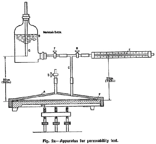
Each tile to be tested shall be placed horizontally, face uppermost, on three points, as shown in Fig. 2a. The upper surface of the tile shall be covered with a special metal cover A, which shall be so designed that the test may be applied to the whole of the exposed surface of the tile to be tested. The metal cover shall be attached to the tile by Faraday Wax* so as to make a water-tight joint between the metal cover and the tile. | ||||
* Faraday Wax is a mixture of colophony resin, beeswax and red oxide of iron and can be obtained from the usual suppliers of chemical stores. | ||||
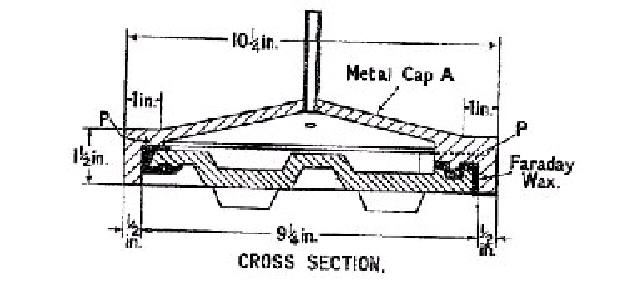
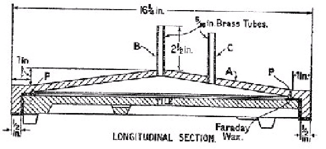
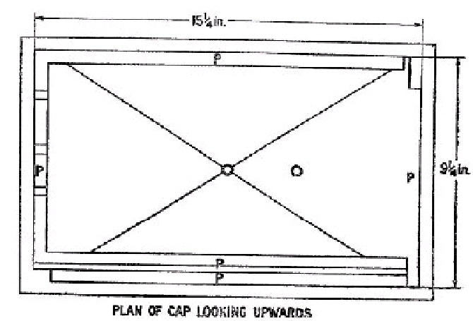
A metal cover suitable for the 15 in. x 9 in. size is shown in detail in Fig. 2b. A similar type of cover should be used for the 18 in. x 10 in. size. | ||||
The metal cover A is provided with air-cock B and tube connection C. The space enclosed by the metal cover A and the upper surface of the tile shall be connected through C to a reservoir of water D and to a calibrated capillary tube E. | ||||
On commencing the test cocks F and B shall be open to admit water to the metal cover A. When this is fully charged with water, cock B shall be closed. The water shall then be allowed to pass into the tile for 24 hours, during which time the level of water in the reservoir D shall be maintained, if necessary, by adding water, above the level of the bottom of tube G. After 24 hours the tap H shall be opened and water allowed to fill the capillary tube E. Tap F shall then be closed and the rate of flow of water into or through the tile shall be deducted from the rate at which the water travels along the calibrated capillary tube E, a stop watch being used to measure the time. The flow of water through the tile shall not exceed that indicated in Clause 14. | ||||
The average of the three tiles tested shall be taken. Should this test fail, a further three tiles shall be selected from the same batch, and the test repeated. If the average of the two tests complies with the limit laid down in Clause 14, the batch shall be considered to have passed the test. | ||||
APPENDIX C. | ||||
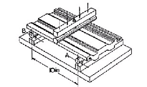
Description of Suitable Type of Testing Apparatus for Transverse Test (See Figs. 1a and 1b). | ||||
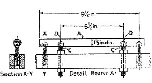
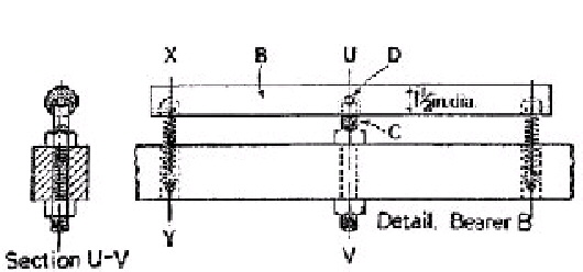
The tile to be tested is placed an bearers A and B.** Bearer A is supported horizontally on two bearer screws C, which carry hardened steel balls D concentric with the bearer (See Fig. 1a). Bearer B is supported on one such bearer screw and ball. The load is applied through bearer E, also having one bearer screw and ball. The bearers A, B and E are of mild steel not less than ¾ in. in diameter and each is provided with two springs which hold the bearers in position. | ||||
** Self-aligning bearings are essential so that when the tile deflects under load the circular bearers rotate about their own axes and eliminate drag at the points of support. | ||||
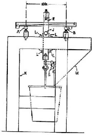
Bearer bar G carries link H which supports load-pan I. Link H is provided with stops J which, when the tile breaks, come into contact with frame K to prevent load-pan I from falling to the ground. Link H is guided in its vertical movement by guides L. | ||||
M is a vessel containing shot, the flow of which through orifice N into load-pan I is controlled by swinging shutter O. Shutter O is provided with handle P and adjusting screw Q which, when the tile breaks, is struck by Link H in falling, thus automatically stopping the flow of shot from vessel M. Stop R limits the movement of shutter O and a fibre washer behind wing-nut S offers frictional resistance to easy movement of shutter O. | ||||
The distance between the bearers A and B at the points of contact with the tile is 10 in. Bearer E is mid-way between bearers A and B measured horizontally. | ||||
Bearers A and B are in the same horizontal plane, parallel to each other and to bearer E. | ||||
The tile to be tested is placed centrally on bearers A and B with its long axis at right angles to the bearers. Bearer E rests upon the upper surface of the tile. The load is applied gradually by adjusting lever P until the orifice in shutter O is opposite the orifice in vessel M, and screw Q is adjusted so that its point is clear of link H. The rate of flow of the shot must be between 100-150 lb. per minute. | ||||
The breaking load includes bearer E, bearer bar G, link H, load-pan I and its contents. | ||||
| ||||
| ||||
| ||||
| ||||
| ||||
| ||||
| ||||
| ||||
Fig. 1a—Essentials of apparatus for transverse test. | ||||
NOTE. The bearer shown as 1½ in. in diameter may be any diameter not less than ¾ in. | ||||
| ||||
| ||||
Fig. 1b—Suggested form of apparatus for transverse test. | ||||
| ||||
| ||||
| ||||
| ||||
| ||||
| ||||
| ||||
| ||||
Fig. 1a—Essentials of apparatus for transverse test. | ||||
GIVEN under my Official Seal, this 3rd day of February, 1950. | ||||
DANIEL MORRISSEY, | ||||
Minister for Industry and Commerce. |