S.I. No. 102/1967 - Merchant Shipping (Grain) Rules, 1967.
S.I. No. 102 of 1967. | |||||||||||||||||||||||||||||||||||||||||||||||||||||||||||||||||||||||||||||||||||||||||||||||||||||||||||||||||||||||||||||||||||||||||||||||||||||||||||||||||||||||||||||||||||||||||||||||||||||||||||||||||||||||||||||||||||||||||||||||||
MERCHANT SHIPPING (GRAIN) RULES, 1967. | |||||||||||||||||||||||||||||||||||||||||||||||||||||||||||||||||||||||||||||||||||||||||||||||||||||||||||||||||||||||||||||||||||||||||||||||||||||||||||||||||||||||||||||||||||||||||||||||||||||||||||||||||||||||||||||||||||||||||||||||||
I, ERSKINE H. CHILDERS, Minister for Transport and Power, in exercise of the powers conferred on me by section 39 (3) of the Merchant Shipping (Safety Convention) Act, 1952 (No. 29 of 1952), and the Transport, Fuel and Power (Transfer of Departmental Administration and Ministerial Functions) Order, 1959 ( S.I. No. 125 of 1959 ), hereby make the following rules: 1.—(1) These Rules may be cited as the Merchant Shipping (Grain) Rules, 1967. | |||||||||||||||||||||||||||||||||||||||||||||||||||||||||||||||||||||||||||||||||||||||||||||||||||||||||||||||||||||||||||||||||||||||||||||||||||||||||||||||||||||||||||||||||||||||||||||||||||||||||||||||||||||||||||||||||||||||||||||||||
(2) These Rules shall come into operation on the 14th day of May, 1967. | |||||||||||||||||||||||||||||||||||||||||||||||||||||||||||||||||||||||||||||||||||||||||||||||||||||||||||||||||||||||||||||||||||||||||||||||||||||||||||||||||||||||||||||||||||||||||||||||||||||||||||||||||||||||||||||||||||||||||||||||||
(3) The Merchant Shipping (Grain) Rules, 1953 ( S.I. No. 348 of 1953 ), are hereby revoked. 2. Every precaution set forth in the Schedule to these Rules is hereby prescribed as being, subject to the provisions of the said Schedule, a precaution to be treated for the purposes of subsections (1) and (2) of section 39 of the Merchant Shipping (Safety Convention) Act, 1952 (No. 29 of 1952) as a necessary or reasonable precaution to prevent grain from shifting, in the case of ships of the following classes— | |||||||||||||||||||||||||||||||||||||||||||||||||||||||||||||||||||||||||||||||||||||||||||||||||||||||||||||||||||||||||||||||||||||||||||||||||||||||||||||||||||||||||||||||||||||||||||||||||||||||||||||||||||||||||||||||||||||||||||||||||
(a) ships which are loaded with grain within any port in the State; | |||||||||||||||||||||||||||||||||||||||||||||||||||||||||||||||||||||||||||||||||||||||||||||||||||||||||||||||||||||||||||||||||||||||||||||||||||||||||||||||||||||||||||||||||||||||||||||||||||||||||||||||||||||||||||||||||||||||||||||||||
(b) ships which, having been loaded with grain outside the State, enter any port in the State so laden. 3. Where these Rules require that a particular fitting, material, appliance or apparatus, or type thereof, shall be fitted or carried in a ship or that any particular provision shall be made, the Minister for Transport and Power may allow any other fitting, material, appliance or apparatus, or type thereof, to be fitted or carried, or any other provision to be made in that ship if he is satisfied that such other fitting, material, appliance or apparatus, or type thereof, or provision is at least as effective as that required by these Rules. | |||||||||||||||||||||||||||||||||||||||||||||||||||||||||||||||||||||||||||||||||||||||||||||||||||||||||||||||||||||||||||||||||||||||||||||||||||||||||||||||||||||||||||||||||||||||||||||||||||||||||||||||||||||||||||||||||||||||||||||||||
|
SCHEDULE. | |||||||||||||||||||||||||||||||||||||||||||||||||||||||||||||||||||||||||||||||||||||||||||||||||||||||||||||||||||||||||||||||||||||||||||||||||||||||||||||||||||||||||||||||||||||||||||||||||||||||||||||||||||||||||||||||||||||||||||||||||
DEFINITIONS. | |||||||||||||||||||||||||||||||||||||||||||||||||||||||||||||||||||||||||||||||||||||||||||||||||||||||||||||||||||||||||||||||||||||||||||||||||||||||||||||||||||||||||||||||||||||||||||||||||||||||||||||||||||||||||||||||||||||||||||||||||
1. In this Schedule— | |||||||||||||||||||||||||||||||||||||||||||||||||||||||||||||||||||||||||||||||||||||||||||||||||||||||||||||||||||||||||||||||||||||||||||||||||||||||||||||||||||||||||||||||||||||||||||||||||||||||||||||||||||||||||||||||||||||||||||||||||
"compartment" means a hold or a cargo space bounded by bulkheads at each end and having decks above and below; | |||||||||||||||||||||||||||||||||||||||||||||||||||||||||||||||||||||||||||||||||||||||||||||||||||||||||||||||||||||||||||||||||||||||||||||||||||||||||||||||||||||||||||||||||||||||||||||||||||||||||||||||||||||||||||||||||||||||||||||||||
"grain" includes wheat, maize, oats, rye, barley, rice, pulses and seeds; | |||||||||||||||||||||||||||||||||||||||||||||||||||||||||||||||||||||||||||||||||||||||||||||||||||||||||||||||||||||||||||||||||||||||||||||||||||||||||||||||||||||||||||||||||||||||||||||||||||||||||||||||||||||||||||||||||||||||||||||||||
"metacentric height" means the distance between the transverse metacentre (M) and the centre of gravity (G) corrected for the free surface effects of liquids in tanks, and, for the purposes of paragraph 4 (3) of this Schedule, for the free surface effects of grain in feeders; | |||||||||||||||||||||||||||||||||||||||||||||||||||||||||||||||||||||||||||||||||||||||||||||||||||||||||||||||||||||||||||||||||||||||||||||||||||||||||||||||||||||||||||||||||||||||||||||||||||||||||||||||||||||||||||||||||||||||||||||||||
"shifting boards" means shifting boards constructed in accordance with the requirements of paragraphs 17 to 20 of this Schedule, or with such other requirements as the Minister for Transport and Power may allow under Rule 3; | |||||||||||||||||||||||||||||||||||||||||||||||||||||||||||||||||||||||||||||||||||||||||||||||||||||||||||||||||||||||||||||||||||||||||||||||||||||||||||||||||||||||||||||||||||||||||||||||||||||||||||||||||||||||||||||||||||||||||||||||||
"two deck ship" means a ship which, in addition to the uppermost complete deck, has a complete or partial deck below that level. | |||||||||||||||||||||||||||||||||||||||||||||||||||||||||||||||||||||||||||||||||||||||||||||||||||||||||||||||||||||||||||||||||||||||||||||||||||||||||||||||||||||||||||||||||||||||||||||||||||||||||||||||||||||||||||||||||||||||||||||||||
STOWAGE | |||||||||||||||||||||||||||||||||||||||||||||||||||||||||||||||||||||||||||||||||||||||||||||||||||||||||||||||||||||||||||||||||||||||||||||||||||||||||||||||||||||||||||||||||||||||||||||||||||||||||||||||||||||||||||||||||||||||||||||||||
Trimming. | |||||||||||||||||||||||||||||||||||||||||||||||||||||||||||||||||||||||||||||||||||||||||||||||||||||||||||||||||||||||||||||||||||||||||||||||||||||||||||||||||||||||||||||||||||||||||||||||||||||||||||||||||||||||||||||||||||||||||||||||||
2.—(1) In compartments entirely filled with bulk grain the grain shall be trimmed so as to fill all the spaces between the beams and in the wings and ends. | |||||||||||||||||||||||||||||||||||||||||||||||||||||||||||||||||||||||||||||||||||||||||||||||||||||||||||||||||||||||||||||||||||||||||||||||||||||||||||||||||||||||||||||||||||||||||||||||||||||||||||||||||||||||||||||||||||||||||||||||||
(2) In compartments partly filled with bulk grain the grain shall be levelled except where this is impracticable. | |||||||||||||||||||||||||||||||||||||||||||||||||||||||||||||||||||||||||||||||||||||||||||||||||||||||||||||||||||||||||||||||||||||||||||||||||||||||||||||||||||||||||||||||||||||||||||||||||||||||||||||||||||||||||||||||||||||||||||||||||
Stowage of full compartments. | |||||||||||||||||||||||||||||||||||||||||||||||||||||||||||||||||||||||||||||||||||||||||||||||||||||||||||||||||||||||||||||||||||||||||||||||||||||||||||||||||||||||||||||||||||||||||||||||||||||||||||||||||||||||||||||||||||||||||||||||||
3.—(1) Except as hereinafter provided, any compartment which is entirely filled with bulk grain shall be divided either (a) by a longitudinal bulkhead or by shifting boards sited not more than 5 per cent. of the moulded breadth of the ship from the centre line or (b) by two or more longitudinal bulkheads or shifting boards provided that the distance between them shall not exceed 60 per cent. of the moulded breadth of the ship, and that trimming hatches of suitable size suitably placed to feed the wings shall be provided at longitudinal intervals of not more than 25 feet with end trimming hatches placed not more than 12 feet from transverse bulkheads. In any compartment which is a hold such longitudinal bulkheads or shifting boards shall extend downwards from the underside of the deck to a distance of at least one-third of the depth of the hold or 8 feet whichever is the greater. In other compartments such longitudinal bulkheads or shifting boards shall extend from deck to deck. | |||||||||||||||||||||||||||||||||||||||||||||||||||||||||||||||||||||||||||||||||||||||||||||||||||||||||||||||||||||||||||||||||||||||||||||||||||||||||||||||||||||||||||||||||||||||||||||||||||||||||||||||||||||||||||||||||||||||||||||||||
(2) The requirements of sub-paragraph (1) of this paragraph shall not apply to— | |||||||||||||||||||||||||||||||||||||||||||||||||||||||||||||||||||||||||||||||||||||||||||||||||||||||||||||||||||||||||||||||||||||||||||||||||||||||||||||||||||||||||||||||||||||||||||||||||||||||||||||||||||||||||||||||||||||||||||||||||
(a) a compartment other than a hold if bagged grain or other suitable cargo therein is tightly stowed in the wings to a width at any point of not less than 20 per cent. of the corresponding breadth of the ship; | |||||||||||||||||||||||||||||||||||||||||||||||||||||||||||||||||||||||||||||||||||||||||||||||||||||||||||||||||||||||||||||||||||||||||||||||||||||||||||||||||||||||||||||||||||||||||||||||||||||||||||||||||||||||||||||||||||||||||||||||||
(b) parts of compartments where the maximum breadth of the deckhead within such parts does not exceed one-half of the moulded breadth of the ship; | |||||||||||||||||||||||||||||||||||||||||||||||||||||||||||||||||||||||||||||||||||||||||||||||||||||||||||||||||||||||||||||||||||||||||||||||||||||||||||||||||||||||||||||||||||||||||||||||||||||||||||||||||||||||||||||||||||||||||||||||||
(c) except in the case of compartments loaded with bulk linseed, those parts of a compartment which, in ships which maintain throughout the voyage a metacentric height of not less than 12 inches in the case of single deck or two deck ships and not less than 14 inches in the case of other ships, are— | |||||||||||||||||||||||||||||||||||||||||||||||||||||||||||||||||||||||||||||||||||||||||||||||||||||||||||||||||||||||||||||||||||||||||||||||||||||||||||||||||||||||||||||||||||||||||||||||||||||||||||||||||||||||||||||||||||||||||||||||||
(i) below and within 7 feet of a feeder, but only below or abreast of a hatchway, if that feeder contains, or all the feeders collectively feeding a compartment contain, not less than 5 per cent. of the quantity of grain carried in the compartment which is fed; | |||||||||||||||||||||||||||||||||||||||||||||||||||||||||||||||||||||||||||||||||||||||||||||||||||||||||||||||||||||||||||||||||||||||||||||||||||||||||||||||||||||||||||||||||||||||||||||||||||||||||||||||||||||||||||||||||||||||||||||||||
(ii) below or abreast of a hatchway where the bulk grain beneath the hatchway is trimmed in the form of a saucer hard up to the deckhead beyond the hatchway to a depth in the centre of the saucer of not less than 6 feet measured below the deck line and is topped off with bagged grain or other suitable bagged cargo so as to fill the hatchway and the saucer below and is stowed tightly against the deckhead, the longitudinal bulkheads, the hatchway beams and the hatchway side and end coamings. | |||||||||||||||||||||||||||||||||||||||||||||||||||||||||||||||||||||||||||||||||||||||||||||||||||||||||||||||||||||||||||||||||||||||||||||||||||||||||||||||||||||||||||||||||||||||||||||||||||||||||||||||||||||||||||||||||||||||||||||||||
Feeders. | |||||||||||||||||||||||||||||||||||||||||||||||||||||||||||||||||||||||||||||||||||||||||||||||||||||||||||||||||||||||||||||||||||||||||||||||||||||||||||||||||||||||||||||||||||||||||||||||||||||||||||||||||||||||||||||||||||||||||||||||||
4.—(1) Any compartment which is entirely filled with bulk grain shall be provided with feeders which shall be constructed in accordance with the requirements of paragraph 22 of this Schedule or with such other requirements as the Minister for Transport and Power may allow under Rule 3 and which shall be placed so as to ensure a free flow of grain to all parts of the compartment containing bulk grain. | |||||||||||||||||||||||||||||||||||||||||||||||||||||||||||||||||||||||||||||||||||||||||||||||||||||||||||||||||||||||||||||||||||||||||||||||||||||||||||||||||||||||||||||||||||||||||||||||||||||||||||||||||||||||||||||||||||||||||||||||||
Provided that feeders shall not be required— | |||||||||||||||||||||||||||||||||||||||||||||||||||||||||||||||||||||||||||||||||||||||||||||||||||||||||||||||||||||||||||||||||||||||||||||||||||||||||||||||||||||||||||||||||||||||||||||||||||||||||||||||||||||||||||||||||||||||||||||||||
(a) when bulk grain is carried in deep tanks which are primarily constructed for the carriage of liquids and in which the greatest width does not exceed one-half of the moulded breadth of the ship, or which are divided by one or more permanent steel longitudinal divisions sited not more than one-half of the moulded breadth of the ship apart. Provided that in such cases the tanks and tank hatchways are completely filled and the tank lids are secured; | |||||||||||||||||||||||||||||||||||||||||||||||||||||||||||||||||||||||||||||||||||||||||||||||||||||||||||||||||||||||||||||||||||||||||||||||||||||||||||||||||||||||||||||||||||||||||||||||||||||||||||||||||||||||||||||||||||||||||||||||||
(b) when bulk grain is trimmed in the form of a saucer hard up to the deckhead beyond the hatchway to a depth in the centre of the saucer of not less than 6 feet measured belowthe deck line and is topped off with bagged grain or other suitable bagged cargo so as to fill the hatchway and the saucer below and is stowed tightly against the deckhead, the longitudinal bulkheads, the hatchway beams and the hatchway side and end coamings. | |||||||||||||||||||||||||||||||||||||||||||||||||||||||||||||||||||||||||||||||||||||||||||||||||||||||||||||||||||||||||||||||||||||||||||||||||||||||||||||||||||||||||||||||||||||||||||||||||||||||||||||||||||||||||||||||||||||||||||||||||
(2) Each feeder shall contain not less than 2 per cent. of the quantity of grain carried below deck level in that part of the compartment which it feeds. | |||||||||||||||||||||||||||||||||||||||||||||||||||||||||||||||||||||||||||||||||||||||||||||||||||||||||||||||||||||||||||||||||||||||||||||||||||||||||||||||||||||||||||||||||||||||||||||||||||||||||||||||||||||||||||||||||||||||||||||||||
(3) Each feeder shall be fitted with a longitudinal bulkhead or shifting boards extending the full depth of the feeder. | |||||||||||||||||||||||||||||||||||||||||||||||||||||||||||||||||||||||||||||||||||||||||||||||||||||||||||||||||||||||||||||||||||||||||||||||||||||||||||||||||||||||||||||||||||||||||||||||||||||||||||||||||||||||||||||||||||||||||||||||||
Provided that such longitudinal bulkhead or shifting boards need not be fitted in feeders in ships which maintain throughout the voyage a metacentric height of not less than 12 inches in the case of single deck or two deck ships and not less than 14 inches in the case of other ships if the feeder contains, or all the feeders collectively feeding a compartment contain, not less than 5 per cent. of the quantity of grain carried below deck level in that compartment and if the free grain surface will not fall below the lower extremities of the feeder or feeders at deck level after allowing for a sinkage of grain amounting to 2 per cent. of the volume of the compartment fed and a shift of the free grain surface to an angle of 12 degrees to the horizontal. In this case the effects of the additional free grain surfaces within the feeders due to the omission of centre-line divisions shall be taken into account in calculating the metacentric height referred to in sub-paragraph (c) of paragraph 3 (2) of this Schedule. The correction to the metacentric height for each feeder shall be made in accordance with the following formula:— | |||||||||||||||||||||||||||||||||||||||||||||||||||||||||||||||||||||||||||||||||||||||||||||||||||||||||||||||||||||||||||||||||||||||||||||||||||||||||||||||||||||||||||||||||||||||||||||||||||||||||||||||||||||||||||||||||||||||||||||||||
| |||||||||||||||||||||||||||||||||||||||||||||||||||||||||||||||||||||||||||||||||||||||||||||||||||||||||||||||||||||||||||||||||||||||||||||||||||||||||||||||||||||||||||||||||||||||||||||||||||||||||||||||||||||||||||||||||||||||||||||||||
where L=Length of feeder in feet and B=Breadth of feeder in feet. | |||||||||||||||||||||||||||||||||||||||||||||||||||||||||||||||||||||||||||||||||||||||||||||||||||||||||||||||||||||||||||||||||||||||||||||||||||||||||||||||||||||||||||||||||||||||||||||||||||||||||||||||||||||||||||||||||||||||||||||||||
Common loading. | |||||||||||||||||||||||||||||||||||||||||||||||||||||||||||||||||||||||||||||||||||||||||||||||||||||||||||||||||||||||||||||||||||||||||||||||||||||||||||||||||||||||||||||||||||||||||||||||||||||||||||||||||||||||||||||||||||||||||||||||||
2. Compartments above one another may be loaded as one compartment under the following conditions:— | |||||||||||||||||||||||||||||||||||||||||||||||||||||||||||||||||||||||||||||||||||||||||||||||||||||||||||||||||||||||||||||||||||||||||||||||||||||||||||||||||||||||||||||||||||||||||||||||||||||||||||||||||||||||||||||||||||||||||||||||||
(a) except as provided in sub-paragraph (c) of paragraph 3(2) of this Schedule a longitudinal bulkhead or shifting boards shall in the 'tween decks of a two deck ship be fitted deck to deck and in all other ships be fitted for the upper third of the total depth of the compartments loaded in common; | |||||||||||||||||||||||||||||||||||||||||||||||||||||||||||||||||||||||||||||||||||||||||||||||||||||||||||||||||||||||||||||||||||||||||||||||||||||||||||||||||||||||||||||||||||||||||||||||||||||||||||||||||||||||||||||||||||||||||||||||||
(b) openings each of at least 4 square feet shall be provided in the wings of the deck immediately below the uppermost deck of the compartments loaded in common and forward and aft of the main hatchway and such openings shall provide, in combination with the main or other hatchways, a feeding distance of not more than 8 feet measured in a fore and aft line; and | |||||||||||||||||||||||||||||||||||||||||||||||||||||||||||||||||||||||||||||||||||||||||||||||||||||||||||||||||||||||||||||||||||||||||||||||||||||||||||||||||||||||||||||||||||||||||||||||||||||||||||||||||||||||||||||||||||||||||||||||||
(c) the requirements of paragraphs 4 and 6 of this Schedule shall apply to compartments loaded in common as if they were one. | |||||||||||||||||||||||||||||||||||||||||||||||||||||||||||||||||||||||||||||||||||||||||||||||||||||||||||||||||||||||||||||||||||||||||||||||||||||||||||||||||||||||||||||||||||||||||||||||||||||||||||||||||||||||||||||||||||||||||||||||||
Trimming and bagging of ends of compartments. | |||||||||||||||||||||||||||||||||||||||||||||||||||||||||||||||||||||||||||||||||||||||||||||||||||||||||||||||||||||||||||||||||||||||||||||||||||||||||||||||||||||||||||||||||||||||||||||||||||||||||||||||||||||||||||||||||||||||||||||||||
6. The bulk grain in any part of a compartment which is more than 25 feet measured in a fore and aft line from the nearest feeder or saucer shall be levelled off at a depth of at least 6 feet below the deck, and the space above filled with bagged grain or other suitable cargo built up on platform which shall be constructed in accordance with the requirements of paragraph 7 of this Schedule. | |||||||||||||||||||||||||||||||||||||||||||||||||||||||||||||||||||||||||||||||||||||||||||||||||||||||||||||||||||||||||||||||||||||||||||||||||||||||||||||||||||||||||||||||||||||||||||||||||||||||||||||||||||||||||||||||||||||||||||||||||
Stowage of partly filled compartments. | |||||||||||||||||||||||||||||||||||||||||||||||||||||||||||||||||||||||||||||||||||||||||||||||||||||||||||||||||||||||||||||||||||||||||||||||||||||||||||||||||||||||||||||||||||||||||||||||||||||||||||||||||||||||||||||||||||||||||||||||||
7.—(1) Except as hereinafter provided any compartment which is partly filled with bulk grain shall be divided either (a) by a longitudinal bulkhead or by shifting boards sited not more than 5 per cent. of the moulded breadth of the ship from the centre line or (b) by two or more longitudinal bulkheads or shifting boards provided that the distance between them shall not exceed 60 per cent. of the moulded breadth of the ship. Such longitudinal bulkheads or shifting boards shall extend from the bottom of the compartment to a height of not less than 2 feet above the surface of the bulk grain. | |||||||||||||||||||||||||||||||||||||||||||||||||||||||||||||||||||||||||||||||||||||||||||||||||||||||||||||||||||||||||||||||||||||||||||||||||||||||||||||||||||||||||||||||||||||||||||||||||||||||||||||||||||||||||||||||||||||||||||||||||
(2) The requirements of sub-paragraph (1) of this paragraph shall not apply to— | |||||||||||||||||||||||||||||||||||||||||||||||||||||||||||||||||||||||||||||||||||||||||||||||||||||||||||||||||||||||||||||||||||||||||||||||||||||||||||||||||||||||||||||||||||||||||||||||||||||||||||||||||||||||||||||||||||||||||||||||||
(a) except in the case of compartments loaded with bulk linseed, those parts of a compartment which are below or abreast of the hatchway in the case of ships in which a metacentric height of not less than 12 inches in the case of single deck or two deck ships and not less than 14 inches in the case of other ships is maintained throughout the voyage; | |||||||||||||||||||||||||||||||||||||||||||||||||||||||||||||||||||||||||||||||||||||||||||||||||||||||||||||||||||||||||||||||||||||||||||||||||||||||||||||||||||||||||||||||||||||||||||||||||||||||||||||||||||||||||||||||||||||||||||||||||
(b) a compartment which is a hold if the bulk grain therein does not exceed one-third of the capacity of the hold or, where such a hold is divided by a shaft tunnel, one-half of the capacity of that hold; | |||||||||||||||||||||||||||||||||||||||||||||||||||||||||||||||||||||||||||||||||||||||||||||||||||||||||||||||||||||||||||||||||||||||||||||||||||||||||||||||||||||||||||||||||||||||||||||||||||||||||||||||||||||||||||||||||||||||||||||||||
(c) a compartment other than a hold if bagged grain or other suitable cargo therein is tightly stowed in the wings to a width at any point of not less than 20 per cent. of the corresponding breadth of the ship; | |||||||||||||||||||||||||||||||||||||||||||||||||||||||||||||||||||||||||||||||||||||||||||||||||||||||||||||||||||||||||||||||||||||||||||||||||||||||||||||||||||||||||||||||||||||||||||||||||||||||||||||||||||||||||||||||||||||||||||||||||
(d) those parts of a compartment where the maximum breadth of the deckhead within such parts does not exceed one-half of the moulded breadth of the ship. | |||||||||||||||||||||||||||||||||||||||||||||||||||||||||||||||||||||||||||||||||||||||||||||||||||||||||||||||||||||||||||||||||||||||||||||||||||||||||||||||||||||||||||||||||||||||||||||||||||||||||||||||||||||||||||||||||||||||||||||||||
(3) If any compartment is partly filled with bulk grain the bulk grain shall be topped off with bagged grain or other suitable cargo tightly stowed and extending to a height of not less than 4 feet in those parts of a compartment which are divided by a longitudinal bulkhead or shifting boards, and to a height of not less than 5 feet in those parts of a compartment which are not so divided. Provided that in the case of a compartment which is a hold in which the bulk grain does not exceed one-third of the capacity of the compartment, or one-half of the capacity of the compartment where it is divided by a shaft tunnel, the depth of the bagged grain or other suitable cargo shall be not less than 4 feet. The bagged grain or other suitable cargo shall be supported on suitable platforms laid over the whole surface of the bulk grain; such platforms shall consist of bearers spaced not more than 4 feet apart and 1 inch boards laid thereon spaced not more than 4 inches apart or of strong separation cloths with adequate over-lapping. | |||||||||||||||||||||||||||||||||||||||||||||||||||||||||||||||||||||||||||||||||||||||||||||||||||||||||||||||||||||||||||||||||||||||||||||||||||||||||||||||||||||||||||||||||||||||||||||||||||||||||||||||||||||||||||||||||||||||||||||||||
Limitation on number of partly filled compartments. | |||||||||||||||||||||||||||||||||||||||||||||||||||||||||||||||||||||||||||||||||||||||||||||||||||||||||||||||||||||||||||||||||||||||||||||||||||||||||||||||||||||||||||||||||||||||||||||||||||||||||||||||||||||||||||||||||||||||||||||||||
8. Except in the case of ships in which a metacentric height of not less than 12 inches in the case of single deck or two deck ships and not less than 14 inches in the case of other ships is maintained throughout the voyage, not more than two compartments may be partly filled with bulk grain except that other compartments may be partly filled with bulk grain provided that they are filled up to the deckhead with bagged grain or other suitable cargo. | |||||||||||||||||||||||||||||||||||||||||||||||||||||||||||||||||||||||||||||||||||||||||||||||||||||||||||||||||||||||||||||||||||||||||||||||||||||||||||||||||||||||||||||||||||||||||||||||||||||||||||||||||||||||||||||||||||||||||||||||||
Bulk grain in 'tween decks and superstructures. | |||||||||||||||||||||||||||||||||||||||||||||||||||||||||||||||||||||||||||||||||||||||||||||||||||||||||||||||||||||||||||||||||||||||||||||||||||||||||||||||||||||||||||||||||||||||||||||||||||||||||||||||||||||||||||||||||||||||||||||||||
9. Bulk grain shall not be carried in compartments which are in the superstructure of a ship or in the 'tween decks of a two deck ship, or in the uppermost 'tween decks of a ship having more than two decks except under the following conditions:— | |||||||||||||||||||||||||||||||||||||||||||||||||||||||||||||||||||||||||||||||||||||||||||||||||||||||||||||||||||||||||||||||||||||||||||||||||||||||||||||||||||||||||||||||||||||||||||||||||||||||||||||||||||||||||||||||||||||||||||||||||
(a) either a metacentric height of not less than 12 inches in the case of single deck or two deck ships and not less than 14 inches in the case of other ships shall be maintained throughout the voyage or, alternatively, the aggregate quantity of bulk grain or other cargo carried in such compartments shall not exceed 28 per cent. by weight of the remaining cargo and the Master shall be satisfied that the ship will have adequate stability throughout the voyage; | |||||||||||||||||||||||||||||||||||||||||||||||||||||||||||||||||||||||||||||||||||||||||||||||||||||||||||||||||||||||||||||||||||||||||||||||||||||||||||||||||||||||||||||||||||||||||||||||||||||||||||||||||||||||||||||||||||||||||||||||||
(b) the deck area of any part of such compartments which contains bulk grain and which is only partly filled shall not exceed 1,000 square feet; and | |||||||||||||||||||||||||||||||||||||||||||||||||||||||||||||||||||||||||||||||||||||||||||||||||||||||||||||||||||||||||||||||||||||||||||||||||||||||||||||||||||||||||||||||||||||||||||||||||||||||||||||||||||||||||||||||||||||||||||||||||
(c) all such compartments in which bulk grain is stowed shall be either subdivided by transverse bulkheads at intervals of not more than 100 feet or, when this distance is exceeded, the excess space shall be entirely filled with bagged grain or other suitable cargo. | |||||||||||||||||||||||||||||||||||||||||||||||||||||||||||||||||||||||||||||||||||||||||||||||||||||||||||||||||||||||||||||||||||||||||||||||||||||||||||||||||||||||||||||||||||||||||||||||||||||||||||||||||||||||||||||||||||||||||||||||||
Stowage of specially suitable ships. | |||||||||||||||||||||||||||||||||||||||||||||||||||||||||||||||||||||||||||||||||||||||||||||||||||||||||||||||||||||||||||||||||||||||||||||||||||||||||||||||||||||||||||||||||||||||||||||||||||||||||||||||||||||||||||||||||||||||||||||||||
10.—(1) The requirements of paragraphs 3 to 9 of this Schedule shall not apply to ships in which the effect of any transverse shift of grain is limited by means of longitudinal divisions or other constructional feature so that the list resulting from a shift of grain and calculated from the assumptions referred to in sub-paragraph (2) of this paragraph does not exceed 5 degrees at any stage of the voyage. | |||||||||||||||||||||||||||||||||||||||||||||||||||||||||||||||||||||||||||||||||||||||||||||||||||||||||||||||||||||||||||||||||||||||||||||||||||||||||||||||||||||||||||||||||||||||||||||||||||||||||||||||||||||||||||||||||||||||||||||||||
(2) In calculating the list referred to in sub-paragraph (1) of this paragraph the assumption shall be made that the grain surfaces which are levelled, or which are constrained by a boundary having an angle of inclination of less than 30 degrees to the horizontal, settle 2 per cent. by volume and move through an angle of 12 degrees with their original surface or 8 degrees if overstowed in accordance with paragraph 7 of this Schedule. | |||||||||||||||||||||||||||||||||||||||||||||||||||||||||||||||||||||||||||||||||||||||||||||||||||||||||||||||||||||||||||||||||||||||||||||||||||||||||||||||||||||||||||||||||||||||||||||||||||||||||||||||||||||||||||||||||||||||||||||||||
(3) Every ship to which paragraphs 3 to 9 of this Schedule do not apply shall carry a grain loading plan and sufficient stability information to show that, for the stowage arrangements to be adopted, the calculated list referred to in sub-paragraph (1) of this paragraph is not exceeded. | |||||||||||||||||||||||||||||||||||||||||||||||||||||||||||||||||||||||||||||||||||||||||||||||||||||||||||||||||||||||||||||||||||||||||||||||||||||||||||||||||||||||||||||||||||||||||||||||||||||||||||||||||||||||||||||||||||||||||||||||||
Water ballast tanks. | |||||||||||||||||||||||||||||||||||||||||||||||||||||||||||||||||||||||||||||||||||||||||||||||||||||||||||||||||||||||||||||||||||||||||||||||||||||||||||||||||||||||||||||||||||||||||||||||||||||||||||||||||||||||||||||||||||||||||||||||||
11. Double bottom tanks which are taken into account in calculating the metacentric height referred to in paragraphs 3, 4, 7, 8, and 9 of this Schedule or calculating the list referred to in paragraph 10 of this Schedule shall have adequate watertight longitudinal sub-division except where the width of the tank measured at half length does not exceed 60 per cent. of the ship's moulded breadth. | |||||||||||||||||||||||||||||||||||||||||||||||||||||||||||||||||||||||||||||||||||||||||||||||||||||||||||||||||||||||||||||||||||||||||||||||||||||||||||||||||||||||||||||||||||||||||||||||||||||||||||||||||||||||||||||||||||||||||||||||||
Bagged grain. | |||||||||||||||||||||||||||||||||||||||||||||||||||||||||||||||||||||||||||||||||||||||||||||||||||||||||||||||||||||||||||||||||||||||||||||||||||||||||||||||||||||||||||||||||||||||||||||||||||||||||||||||||||||||||||||||||||||||||||||||||
12. Bagged grain shall be carried in sound bags which shall be securely closed and, except as provided in sub-paragraph (b) of paragraph 15 of this Schedule, well filled. | |||||||||||||||||||||||||||||||||||||||||||||||||||||||||||||||||||||||||||||||||||||||||||||||||||||||||||||||||||||||||||||||||||||||||||||||||||||||||||||||||||||||||||||||||||||||||||||||||||||||||||||||||||||||||||||||||||||||||||||||||
Loading of home trade ships. | |||||||||||||||||||||||||||||||||||||||||||||||||||||||||||||||||||||||||||||||||||||||||||||||||||||||||||||||||||||||||||||||||||||||||||||||||||||||||||||||||||||||||||||||||||||||||||||||||||||||||||||||||||||||||||||||||||||||||||||||||
13. Except in regard to the stowage of bulk grain in the 'tween decks of a two deck ship or the uppermost 'tween decks of a ship having more than two decks, the foregoing requirements of this Schedule shall not apply to any home-trade ship in which bulk grain is carried provided that the precautions to prevent the grain from shifting required by paragraphs 14 and 15 of this Schedule are taken. | |||||||||||||||||||||||||||||||||||||||||||||||||||||||||||||||||||||||||||||||||||||||||||||||||||||||||||||||||||||||||||||||||||||||||||||||||||||||||||||||||||||||||||||||||||||||||||||||||||||||||||||||||||||||||||||||||||||||||||||||||
Stowage of full compartments in home trade ships. | |||||||||||||||||||||||||||||||||||||||||||||||||||||||||||||||||||||||||||||||||||||||||||||||||||||||||||||||||||||||||||||||||||||||||||||||||||||||||||||||||||||||||||||||||||||||||||||||||||||||||||||||||||||||||||||||||||||||||||||||||
14. In home-trade ships the stowage in any compartment which is entirely filled with bulk grain shall be as follows:— | |||||||||||||||||||||||||||||||||||||||||||||||||||||||||||||||||||||||||||||||||||||||||||||||||||||||||||||||||||||||||||||||||||||||||||||||||||||||||||||||||||||||||||||||||||||||||||||||||||||||||||||||||||||||||||||||||||||||||||||||||
(a) the grain shall be trimmed tightly into the wings, ends and beam spaces; and | |||||||||||||||||||||||||||||||||||||||||||||||||||||||||||||||||||||||||||||||||||||||||||||||||||||||||||||||||||||||||||||||||||||||||||||||||||||||||||||||||||||||||||||||||||||||||||||||||||||||||||||||||||||||||||||||||||||||||||||||||
(b) either the hatchway shall contain not less than 4 per cent. of the quantity of bulk grain carried below deck level in the compartment which it feeds or, alternatively, the bulk grain beneath the hatchway shall be trimmed in the formof a saucer and topped off with bagged grain or other suitable bagged cargo in the manner specified in sub-paragraph (c) (ii) of paragraph 3(2) of this Schedule. | |||||||||||||||||||||||||||||||||||||||||||||||||||||||||||||||||||||||||||||||||||||||||||||||||||||||||||||||||||||||||||||||||||||||||||||||||||||||||||||||||||||||||||||||||||||||||||||||||||||||||||||||||||||||||||||||||||||||||||||||||
Stowage of partly-filled compartments in home trade ships. | |||||||||||||||||||||||||||||||||||||||||||||||||||||||||||||||||||||||||||||||||||||||||||||||||||||||||||||||||||||||||||||||||||||||||||||||||||||||||||||||||||||||||||||||||||||||||||||||||||||||||||||||||||||||||||||||||||||||||||||||||
15. In home-trade ships the stowage in any compartment which is partly filled with bulk grain shall comply with the requirement of paragraph 7 of this Schedule. | |||||||||||||||||||||||||||||||||||||||||||||||||||||||||||||||||||||||||||||||||||||||||||||||||||||||||||||||||||||||||||||||||||||||||||||||||||||||||||||||||||||||||||||||||||||||||||||||||||||||||||||||||||||||||||||||||||||||||||||||||
Provided that not more than two compartments may be stowed in either of the following ways:— | |||||||||||||||||||||||||||||||||||||||||||||||||||||||||||||||||||||||||||||||||||||||||||||||||||||||||||||||||||||||||||||||||||||||||||||||||||||||||||||||||||||||||||||||||||||||||||||||||||||||||||||||||||||||||||||||||||||||||||||||||
(a) The bulk grain shall be levelled off and overstowed with at least two tiers of bagged grain laid on separation cloths, or with other suitable cargo supported on platforms or separation cloths; or | |||||||||||||||||||||||||||||||||||||||||||||||||||||||||||||||||||||||||||||||||||||||||||||||||||||||||||||||||||||||||||||||||||||||||||||||||||||||||||||||||||||||||||||||||||||||||||||||||||||||||||||||||||||||||||||||||||||||||||||||||
(b) (i) The bulk grain shall be divided from the empty space in the hold by one of the following methods:— | |||||||||||||||||||||||||||||||||||||||||||||||||||||||||||||||||||||||||||||||||||||||||||||||||||||||||||||||||||||||||||||||||||||||||||||||||||||||||||||||||||||||||||||||||||||||||||||||||||||||||||||||||||||||||||||||||||||||||||||||||
Method 1. A transverse vertical wood grain-tight bulkhead shall be fitted in the fore part of the compartment in such a way as to reduce the capacity of the compartment to that required for the stowage of the grain. | |||||||||||||||||||||||||||||||||||||||||||||||||||||||||||||||||||||||||||||||||||||||||||||||||||||||||||||||||||||||||||||||||||||||||||||||||||||||||||||||||||||||||||||||||||||||||||||||||||||||||||||||||||||||||||||||||||||||||||||||||
Method 2. A strongly and tightly constructed transverse vertical bulkhead of bagged grain shall be used. The bulkhead shall contain sufficient rows of bags laid in a fore and aft direction to enable it to withstand the effects of pitching and scending during the voyage. Its foundation shall be on the floor of the compartment and shall consist of not less than four rows of bags. Provided adequate support is maintained the bulkhead may be narrowed to two rows of bags at the top. | |||||||||||||||||||||||||||||||||||||||||||||||||||||||||||||||||||||||||||||||||||||||||||||||||||||||||||||||||||||||||||||||||||||||||||||||||||||||||||||||||||||||||||||||||||||||||||||||||||||||||||||||||||||||||||||||||||||||||||||||||
Method 3. A sloping bulkhead shall be constructed of stepped bags of grain. The bags shall be packed tightly together and bedded into the grain in a fore and aft direction. They shall lie horizontally and overlap not less than one-half of their length. The lowest tier shall be arranged so as to rest upon a firm and solid foundation and shall be placed on the floor of the compartment or on separation cloths laid on a levelled grain surface reaching to one of the ship's transverse bulkheads. The bags shall be well locked into the frames at the ship's side and a double tier shall be laid at the sides of the compartment. The bulkheads shall be secured in the hatchway and the top tier of bags shall be so wedged tightly against the web beams or the hatch end coamings that they will be secured against fore and aft movement. | |||||||||||||||||||||||||||||||||||||||||||||||||||||||||||||||||||||||||||||||||||||||||||||||||||||||||||||||||||||||||||||||||||||||||||||||||||||||||||||||||||||||||||||||||||||||||||||||||||||||||||||||||||||||||||||||||||||||||||||||||
The bulk grain shall be stowed in such a way a to confine its loose surface within the limits of the hatchway in such a manner that it will serve as a feeder. The part of the compartment containing bulk grain shall be entirely filled and the grain shall be so confined as to prevent anyof it getting into the empty part of the compartment. The bulk grain shall be trimmed tightly into one end of the compartment, the wings and beam spaces shall be filled, and as much grain as possible shall be stowed at the same end of the hatchway to ensure a sufficient supply for feeding purposes. | |||||||||||||||||||||||||||||||||||||||||||||||||||||||||||||||||||||||||||||||||||||||||||||||||||||||||||||||||||||||||||||||||||||||||||||||||||||||||||||||||||||||||||||||||||||||||||||||||||||||||||||||||||||||||||||||||||||||||||||||||
(iii) Where the bulk grain is insufficient to reach up into the hatchway the grain surface shall be trimmed level athwartships and the fore and aft slope reduced considerably below the natural angle of repose and the surface of the grain shall be secured by not less than two tiers of bagged grain or by other suitable cargo tightly stowed. The bagged grain or other suitable cargo shall be supported on suitable platforms or on strong separation cloths laid over the whole surface of the bulk grain. | |||||||||||||||||||||||||||||||||||||||||||||||||||||||||||||||||||||||||||||||||||||||||||||||||||||||||||||||||||||||||||||||||||||||||||||||||||||||||||||||||||||||||||||||||||||||||||||||||||||||||||||||||||||||||||||||||||||||||||||||||
(iv) The bags referred to in this sub-paragraph shall be loosely filled and, where used in the construction of bulkheads, shall be arranged with their mouths laid towards the bulk grain. | |||||||||||||||||||||||||||||||||||||||||||||||||||||||||||||||||||||||||||||||||||||||||||||||||||||||||||||||||||||||||||||||||||||||||||||||||||||||||||||||||||||||||||||||||||||||||||||||||||||||||||||||||||||||||||||||||||||||||||||||||
GRAIN FITTINGS | |||||||||||||||||||||||||||||||||||||||||||||||||||||||||||||||||||||||||||||||||||||||||||||||||||||||||||||||||||||||||||||||||||||||||||||||||||||||||||||||||||||||||||||||||||||||||||||||||||||||||||||||||||||||||||||||||||||||||||||||||
General. | |||||||||||||||||||||||||||||||||||||||||||||||||||||||||||||||||||||||||||||||||||||||||||||||||||||||||||||||||||||||||||||||||||||||||||||||||||||||||||||||||||||||||||||||||||||||||||||||||||||||||||||||||||||||||||||||||||||||||||||||||
16. All timber used for grain fittings shall be of good sound quality and of a type and grade which has been proved to be satisfactory for this purpose. The actual finished dimensions of the timber shall be in accordance with the dimensions hereinafter specified in this Schedule. Plywood of an exterior type bonded with waterproof glue and fitted so that the direction of the grain in the face plies is perpendicular to the supporting uprights or binder may be used provided that its strength is equivalent to that of solid timber of the appropriate scantlings. | |||||||||||||||||||||||||||||||||||||||||||||||||||||||||||||||||||||||||||||||||||||||||||||||||||||||||||||||||||||||||||||||||||||||||||||||||||||||||||||||||||||||||||||||||||||||||||||||||||||||||||||||||||||||||||||||||||||||||||||||||
Shifting boards. | |||||||||||||||||||||||||||||||||||||||||||||||||||||||||||||||||||||||||||||||||||||||||||||||||||||||||||||||||||||||||||||||||||||||||||||||||||||||||||||||||||||||||||||||||||||||||||||||||||||||||||||||||||||||||||||||||||||||||||||||||
17.—(1) Shifting boards shall have a thickness of not less than 2 inches and shall be fitted grain-tight and where necessary supported by uprights. | |||||||||||||||||||||||||||||||||||||||||||||||||||||||||||||||||||||||||||||||||||||||||||||||||||||||||||||||||||||||||||||||||||||||||||||||||||||||||||||||||||||||||||||||||||||||||||||||||||||||||||||||||||||||||||||||||||||||||||||||||
(2) The maximum unsupported span for shifting boards of various thicknesses shall be as follows:— | |||||||||||||||||||||||||||||||||||||||||||||||||||||||||||||||||||||||||||||||||||||||||||||||||||||||||||||||||||||||||||||||||||||||||||||||||||||||||||||||||||||||||||||||||||||||||||||||||||||||||||||||||||||||||||||||||||||||||||||||||
| |||||||||||||||||||||||||||||||||||||||||||||||||||||||||||||||||||||||||||||||||||||||||||||||||||||||||||||||||||||||||||||||||||||||||||||||||||||||||||||||||||||||||||||||||||||||||||||||||||||||||||||||||||||||||||||||||||||||||||||||||
(3) The ends of all shifting boards shall be securely housed with a 3 inch minimum bearing length. | |||||||||||||||||||||||||||||||||||||||||||||||||||||||||||||||||||||||||||||||||||||||||||||||||||||||||||||||||||||||||||||||||||||||||||||||||||||||||||||||||||||||||||||||||||||||||||||||||||||||||||||||||||||||||||||||||||||||||||||||||
(4) Where 2½ inch or 3 inch shifting boards are used, the boards may be butt-jointed in way of the uprights and at least 4 inches of board shall be supported. Where 2 inch shifting boards are used the joints shall overlap by at least 9 inches at the uprights. | |||||||||||||||||||||||||||||||||||||||||||||||||||||||||||||||||||||||||||||||||||||||||||||||||||||||||||||||||||||||||||||||||||||||||||||||||||||||||||||||||||||||||||||||||||||||||||||||||||||||||||||||||||||||||||||||||||||||||||||||||
(5) Where no permanent grain-tight divisions exist wood filling pieces of the same thickness as the shifting boards shall be securely fitted grain-tight between the beams. | |||||||||||||||||||||||||||||||||||||||||||||||||||||||||||||||||||||||||||||||||||||||||||||||||||||||||||||||||||||||||||||||||||||||||||||||||||||||||||||||||||||||||||||||||||||||||||||||||||||||||||||||||||||||||||||||||||||||||||||||||
Uprights. | |||||||||||||||||||||||||||||||||||||||||||||||||||||||||||||||||||||||||||||||||||||||||||||||||||||||||||||||||||||||||||||||||||||||||||||||||||||||||||||||||||||||||||||||||||||||||||||||||||||||||||||||||||||||||||||||||||||||||||||||||
18.—(1) The horizontal distances between the centres of the uprights shall be appropriate for the spans of boards in paragraph 17(2) of this Schedule and in no case greater than 13 feet. Unless means are provided to prevent the ends of uprights being dislodged from their sockets the depth of housing at each end of each upright shall be not less than 3 inches. If an upright is not secured at the top, the uppermost shore or stay shall be not more than 18 inches down from the deck or top of the upright. | |||||||||||||||||||||||||||||||||||||||||||||||||||||||||||||||||||||||||||||||||||||||||||||||||||||||||||||||||||||||||||||||||||||||||||||||||||||||||||||||||||||||||||||||||||||||||||||||||||||||||||||||||||||||||||||||||||||||||||||||||
(2) The vertical unsupported span of an upright supported on each side by wood shores complying with the requirements of paragraph 19(2) of this Schedule or by wire stays complying with the requirements of paragraph 20(1) of this Schedule shall be either the distance between the shores or stays or the distance from the ends of the upright to the nearest shore or stay whichever is the greater. | |||||||||||||||||||||||||||||||||||||||||||||||||||||||||||||||||||||||||||||||||||||||||||||||||||||||||||||||||||||||||||||||||||||||||||||||||||||||||||||||||||||||||||||||||||||||||||||||||||||||||||||||||||||||||||||||||||||||||||||||||
(3) Wood uprights shall consist of two planks, one on each side of the shifting boards. They shall be throughbolted in a reeled pattern at alternate boards and shall conform with the scantlings given in the following Table 1— | |||||||||||||||||||||||||||||||||||||||||||||||||||||||||||||||||||||||||||||||||||||||||||||||||||||||||||||||||||||||||||||||||||||||||||||||||||||||||||||||||||||||||||||||||||||||||||||||||||||||||||||||||||||||||||||||||||||||||||||||||
TABLE 1. | |||||||||||||||||||||||||||||||||||||||||||||||||||||||||||||||||||||||||||||||||||||||||||||||||||||||||||||||||||||||||||||||||||||||||||||||||||||||||||||||||||||||||||||||||||||||||||||||||||||||||||||||||||||||||||||||||||||||||||||||||
SCANTLINGS OF DOUBLE WOOD PLANK UPRIGHTS IN INCHES | |||||||||||||||||||||||||||||||||||||||||||||||||||||||||||||||||||||||||||||||||||||||||||||||||||||||||||||||||||||||||||||||||||||||||||||||||||||||||||||||||||||||||||||||||||||||||||||||||||||||||||||||||||||||||||||||||||||||||||||||||
| |||||||||||||||||||||||||||||||||||||||||||||||||||||||||||||||||||||||||||||||||||||||||||||||||||||||||||||||||||||||||||||||||||||||||||||||||||||||||||||||||||||||||||||||||||||||||||||||||||||||||||||||||||||||||||||||||||||||||||||||||
At intermediate vertical spans or horizontal distances the scantlings applicable to the next higher span or spacing shall apply. | |||||||||||||||||||||||||||||||||||||||||||||||||||||||||||||||||||||||||||||||||||||||||||||||||||||||||||||||||||||||||||||||||||||||||||||||||||||||||||||||||||||||||||||||||||||||||||||||||||||||||||||||||||||||||||||||||||||||||||||||||
(4) Steel uprights shall conform with the section moduli given in the following Table 2— | |||||||||||||||||||||||||||||||||||||||||||||||||||||||||||||||||||||||||||||||||||||||||||||||||||||||||||||||||||||||||||||||||||||||||||||||||||||||||||||||||||||||||||||||||||||||||||||||||||||||||||||||||||||||||||||||||||||||||||||||||
TABLE 2. | |||||||||||||||||||||||||||||||||||||||||||||||||||||||||||||||||||||||||||||||||||||||||||||||||||||||||||||||||||||||||||||||||||||||||||||||||||||||||||||||||||||||||||||||||||||||||||||||||||||||||||||||||||||||||||||||||||||||||||||||||
SECTION MODULUS OF STEEL UPRIGHTS IN INCHES3 | |||||||||||||||||||||||||||||||||||||||||||||||||||||||||||||||||||||||||||||||||||||||||||||||||||||||||||||||||||||||||||||||||||||||||||||||||||||||||||||||||||||||||||||||||||||||||||||||||||||||||||||||||||||||||||||||||||||||||||||||||
| |||||||||||||||||||||||||||||||||||||||||||||||||||||||||||||||||||||||||||||||||||||||||||||||||||||||||||||||||||||||||||||||||||||||||||||||||||||||||||||||||||||||||||||||||||||||||||||||||||||||||||||||||||||||||||||||||||||||||||||||||
At intermediate vertical spans or horizontal distances the section modulus of steel uprights shall be obtained by interpolation. | |||||||||||||||||||||||||||||||||||||||||||||||||||||||||||||||||||||||||||||||||||||||||||||||||||||||||||||||||||||||||||||||||||||||||||||||||||||||||||||||||||||||||||||||||||||||||||||||||||||||||||||||||||||||||||||||||||||||||||||||||
(5) Where uprights are formed by two angle bars or other sections, one fitted each side of the shifting boards and throughbolted at alternate boards, the effective section modulus shall be taken as 70 per cent. of the section modulus obtained by considering each angle bar or section to be fully effective about the neutral axis of the combined section. | |||||||||||||||||||||||||||||||||||||||||||||||||||||||||||||||||||||||||||||||||||||||||||||||||||||||||||||||||||||||||||||||||||||||||||||||||||||||||||||||||||||||||||||||||||||||||||||||||||||||||||||||||||||||||||||||||||||||||||||||||
(6) Uprights constructed of metals other than steel shall be of equivalent strength to the uprights referred to in Table 2. | |||||||||||||||||||||||||||||||||||||||||||||||||||||||||||||||||||||||||||||||||||||||||||||||||||||||||||||||||||||||||||||||||||||||||||||||||||||||||||||||||||||||||||||||||||||||||||||||||||||||||||||||||||||||||||||||||||||||||||||||||
Shores. | |||||||||||||||||||||||||||||||||||||||||||||||||||||||||||||||||||||||||||||||||||||||||||||||||||||||||||||||||||||||||||||||||||||||||||||||||||||||||||||||||||||||||||||||||||||||||||||||||||||||||||||||||||||||||||||||||||||||||||||||||
19.—(1) Any wood shore shall be in a single piece and shall be securely fixed at each end and heeled against the permanent structure of the ship except that it shall not bear directly against the side plating of the ship. | |||||||||||||||||||||||||||||||||||||||||||||||||||||||||||||||||||||||||||||||||||||||||||||||||||||||||||||||||||||||||||||||||||||||||||||||||||||||||||||||||||||||||||||||||||||||||||||||||||||||||||||||||||||||||||||||||||||||||||||||||
(2) Subject to the provisions of sub-paragraphs (3) and (4) of this paragraph the minimum size of wood shores shall be as follows:— | |||||||||||||||||||||||||||||||||||||||||||||||||||||||||||||||||||||||||||||||||||||||||||||||||||||||||||||||||||||||||||||||||||||||||||||||||||||||||||||||||||||||||||||||||||||||||||||||||||||||||||||||||||||||||||||||||||||||||||||||||
| |||||||||||||||||||||||||||||||||||||||||||||||||||||||||||||||||||||||||||||||||||||||||||||||||||||||||||||||||||||||||||||||||||||||||||||||||||||||||||||||||||||||||||||||||||||||||||||||||||||||||||||||||||||||||||||||||||||||||||||||||
Shores of 24 feet or more in length shall be securely bridged at approximately mid-length. | |||||||||||||||||||||||||||||||||||||||||||||||||||||||||||||||||||||||||||||||||||||||||||||||||||||||||||||||||||||||||||||||||||||||||||||||||||||||||||||||||||||||||||||||||||||||||||||||||||||||||||||||||||||||||||||||||||||||||||||||||
(3) Where the vertical unsupported span of the upright is less than 8 feet or the horizontal distance between the uprights is less than 13 feet, the size of the shore may be reduced in proportion. | |||||||||||||||||||||||||||||||||||||||||||||||||||||||||||||||||||||||||||||||||||||||||||||||||||||||||||||||||||||||||||||||||||||||||||||||||||||||||||||||||||||||||||||||||||||||||||||||||||||||||||||||||||||||||||||||||||||||||||||||||
(4) Where the angle of the shore to the horizontal exceeds 10 degrees the next larger shore to that required by sub-paragraph (2) of this paragraph shall be fitted provided that in no case shall the angle between any shore and the horizontal exceed 45 degrees. | |||||||||||||||||||||||||||||||||||||||||||||||||||||||||||||||||||||||||||||||||||||||||||||||||||||||||||||||||||||||||||||||||||||||||||||||||||||||||||||||||||||||||||||||||||||||||||||||||||||||||||||||||||||||||||||||||||||||||||||||||
Stays. | |||||||||||||||||||||||||||||||||||||||||||||||||||||||||||||||||||||||||||||||||||||||||||||||||||||||||||||||||||||||||||||||||||||||||||||||||||||||||||||||||||||||||||||||||||||||||||||||||||||||||||||||||||||||||||||||||||||||||||||||||
20.—(1) Where stays are used the following provisions shall apply:— | |||||||||||||||||||||||||||||||||||||||||||||||||||||||||||||||||||||||||||||||||||||||||||||||||||||||||||||||||||||||||||||||||||||||||||||||||||||||||||||||||||||||||||||||||||||||||||||||||||||||||||||||||||||||||||||||||||||||||||||||||
(a) the stays shall be fitted horizontally and shall be of 3 inch circumference galvanised flexible steel wire rope of 6 x 12 construction having a breaking strength of not less than 18·6 tons; | |||||||||||||||||||||||||||||||||||||||||||||||||||||||||||||||||||||||||||||||||||||||||||||||||||||||||||||||||||||||||||||||||||||||||||||||||||||||||||||||||||||||||||||||||||||||||||||||||||||||||||||||||||||||||||||||||||||||||||||||||
(b) the rigging screws shall be 1¼ inches diameter and shall be fitted in accessible positions; | |||||||||||||||||||||||||||||||||||||||||||||||||||||||||||||||||||||||||||||||||||||||||||||||||||||||||||||||||||||||||||||||||||||||||||||||||||||||||||||||||||||||||||||||||||||||||||||||||||||||||||||||||||||||||||||||||||||||||||||||||
(c) the shackles shall be 1 inch; | |||||||||||||||||||||||||||||||||||||||||||||||||||||||||||||||||||||||||||||||||||||||||||||||||||||||||||||||||||||||||||||||||||||||||||||||||||||||||||||||||||||||||||||||||||||||||||||||||||||||||||||||||||||||||||||||||||||||||||||||||
(d) the eye bolts through the upright shall be 1¼ inches; and | |||||||||||||||||||||||||||||||||||||||||||||||||||||||||||||||||||||||||||||||||||||||||||||||||||||||||||||||||||||||||||||||||||||||||||||||||||||||||||||||||||||||||||||||||||||||||||||||||||||||||||||||||||||||||||||||||||||||||||||||||
(e) either eye plates of 1 inch thickness shall be securely attached to the side stringers or frames, or 1 inch shackles passed through the frame. | |||||||||||||||||||||||||||||||||||||||||||||||||||||||||||||||||||||||||||||||||||||||||||||||||||||||||||||||||||||||||||||||||||||||||||||||||||||||||||||||||||||||||||||||||||||||||||||||||||||||||||||||||||||||||||||||||||||||||||||||||
(2) Where shifting boards do not extend to the full depth of the hold the shifting boards and their uprights shall be supported or stayed so as to be as efficient as shifting boards which do extend to the full depth of the hold. | |||||||||||||||||||||||||||||||||||||||||||||||||||||||||||||||||||||||||||||||||||||||||||||||||||||||||||||||||||||||||||||||||||||||||||||||||||||||||||||||||||||||||||||||||||||||||||||||||||||||||||||||||||||||||||||||||||||||||||||||||
Construction of feeders and bulkheads. | |||||||||||||||||||||||||||||||||||||||||||||||||||||||||||||||||||||||||||||||||||||||||||||||||||||||||||||||||||||||||||||||||||||||||||||||||||||||||||||||||||||||||||||||||||||||||||||||||||||||||||||||||||||||||||||||||||||||||||||||||
21. Feeders and bulkheads shall be of sufficient strength to withstand the pressure of the grain and shall be grain-tight. | |||||||||||||||||||||||||||||||||||||||||||||||||||||||||||||||||||||||||||||||||||||||||||||||||||||||||||||||||||||||||||||||||||||||||||||||||||||||||||||||||||||||||||||||||||||||||||||||||||||||||||||||||||||||||||||||||||||||||||||||||
Construction of wood feeders. | |||||||||||||||||||||||||||||||||||||||||||||||||||||||||||||||||||||||||||||||||||||||||||||||||||||||||||||||||||||||||||||||||||||||||||||||||||||||||||||||||||||||||||||||||||||||||||||||||||||||||||||||||||||||||||||||||||||||||||||||||
22.—(1) The construction of wood feeders shall conform to either of the specifications and methods set out in sub-paragraphs (2) and (3) of this paragraph. | |||||||||||||||||||||||||||||||||||||||||||||||||||||||||||||||||||||||||||||||||||||||||||||||||||||||||||||||||||||||||||||||||||||||||||||||||||||||||||||||||||||||||||||||||||||||||||||||||||||||||||||||||||||||||||||||||||||||||||||||||
(2) In feeders constructed of horizontal boards and supported by uprights the following provisions shall apply:— | |||||||||||||||||||||||||||||||||||||||||||||||||||||||||||||||||||||||||||||||||||||||||||||||||||||||||||||||||||||||||||||||||||||||||||||||||||||||||||||||||||||||||||||||||||||||||||||||||||||||||||||||||||||||||||||||||||||||||||||||||
(a) Boards | |||||||||||||||||||||||||||||||||||||||||||||||||||||||||||||||||||||||||||||||||||||||||||||||||||||||||||||||||||||||||||||||||||||||||||||||||||||||||||||||||||||||||||||||||||||||||||||||||||||||||||||||||||||||||||||||||||||||||||||||||
The unsupported span of 2½ inch boards shall not exceed the maximum permitted unsupported spans specified in Tables 3 and 4 for feeder sides and feeder ends respectively. The unsupported span for other boards which shall be not less than 2½ inches thick shall not exceed that obtained by modifying the span specified in the aforesaid Tables in direct proportion to the thickness of the board. | |||||||||||||||||||||||||||||||||||||||||||||||||||||||||||||||||||||||||||||||||||||||||||||||||||||||||||||||||||||||||||||||||||||||||||||||||||||||||||||||||||||||||||||||||||||||||||||||||||||||||||||||||||||||||||||||||||||||||||||||||
TABLE 3. | |||||||||||||||||||||||||||||||||||||||||||||||||||||||||||||||||||||||||||||||||||||||||||||||||||||||||||||||||||||||||||||||||||||||||||||||||||||||||||||||||||||||||||||||||||||||||||||||||||||||||||||||||||||||||||||||||||||||||||||||||
MAXIMUM PERMITTED UNSUPPORTED SPAN OF 2½ INCH HORIZONTAL BOARDS ON FEEDER SIDES IN FEET. | |||||||||||||||||||||||||||||||||||||||||||||||||||||||||||||||||||||||||||||||||||||||||||||||||||||||||||||||||||||||||||||||||||||||||||||||||||||||||||||||||||||||||||||||||||||||||||||||||||||||||||||||||||||||||||||||||||||||||||||||||
| |||||||||||||||||||||||||||||||||||||||||||||||||||||||||||||||||||||||||||||||||||||||||||||||||||||||||||||||||||||||||||||||||||||||||||||||||||||||||||||||||||||||||||||||||||||||||||||||||||||||||||||||||||||||||||||||||||||||||||||||||
At intermediate feeder heights or breadths the maximum unsupported span of 2½ inch boards shall be obtained by interpolation. | |||||||||||||||||||||||||||||||||||||||||||||||||||||||||||||||||||||||||||||||||||||||||||||||||||||||||||||||||||||||||||||||||||||||||||||||||||||||||||||||||||||||||||||||||||||||||||||||||||||||||||||||||||||||||||||||||||||||||||||||||
TABLE 4. | |||||||||||||||||||||||||||||||||||||||||||||||||||||||||||||||||||||||||||||||||||||||||||||||||||||||||||||||||||||||||||||||||||||||||||||||||||||||||||||||||||||||||||||||||||||||||||||||||||||||||||||||||||||||||||||||||||||||||||||||||
MAXIMUM PERMITTED UNSUPPORTED SPAN OF 2½ INCH HORIZONTAL BOARDS ON FEEDER ENDS IN FEET. | |||||||||||||||||||||||||||||||||||||||||||||||||||||||||||||||||||||||||||||||||||||||||||||||||||||||||||||||||||||||||||||||||||||||||||||||||||||||||||||||||||||||||||||||||||||||||||||||||||||||||||||||||||||||||||||||||||||||||||||||||
| |||||||||||||||||||||||||||||||||||||||||||||||||||||||||||||||||||||||||||||||||||||||||||||||||||||||||||||||||||||||||||||||||||||||||||||||||||||||||||||||||||||||||||||||||||||||||||||||||||||||||||||||||||||||||||||||||||||||||||||||||
At intermediate feeder heights or lengths the maximum unsupported span of 2½ inch boards shall be obtained by interpolation. | |||||||||||||||||||||||||||||||||||||||||||||||||||||||||||||||||||||||||||||||||||||||||||||||||||||||||||||||||||||||||||||||||||||||||||||||||||||||||||||||||||||||||||||||||||||||||||||||||||||||||||||||||||||||||||||||||||||||||||||||||
(b) Feeder uprights. | |||||||||||||||||||||||||||||||||||||||||||||||||||||||||||||||||||||||||||||||||||||||||||||||||||||||||||||||||||||||||||||||||||||||||||||||||||||||||||||||||||||||||||||||||||||||||||||||||||||||||||||||||||||||||||||||||||||||||||||||||
The section modulus in inches3 of uprights used to support the horizontal boards shall be not less than that given by the expression 1·5 Psh1 in the case of wood uprights or the expression 0·15 Psh1 in the case of steel uprights where— | |||||||||||||||||||||||||||||||||||||||||||||||||||||||||||||||||||||||||||||||||||||||||||||||||||||||||||||||||||||||||||||||||||||||||||||||||||||||||||||||||||||||||||||||||||||||||||||||||||||||||||||||||||||||||||||||||||||||||||||||||
P =pressure load in tons per foot length of feeder side, or breadth of feeder end, on the portion of feeder side or feeder end supported by the upright, obtained respectively from Tables 5 and 6; | |||||||||||||||||||||||||||||||||||||||||||||||||||||||||||||||||||||||||||||||||||||||||||||||||||||||||||||||||||||||||||||||||||||||||||||||||||||||||||||||||||||||||||||||||||||||||||||||||||||||||||||||||||||||||||||||||||||||||||||||||
s =half the distance in feet between the nearest upright or support on each side; and | |||||||||||||||||||||||||||||||||||||||||||||||||||||||||||||||||||||||||||||||||||||||||||||||||||||||||||||||||||||||||||||||||||||||||||||||||||||||||||||||||||||||||||||||||||||||||||||||||||||||||||||||||||||||||||||||||||||||||||||||||
h1 =unsupported height of upright in feet. | |||||||||||||||||||||||||||||||||||||||||||||||||||||||||||||||||||||||||||||||||||||||||||||||||||||||||||||||||||||||||||||||||||||||||||||||||||||||||||||||||||||||||||||||||||||||||||||||||||||||||||||||||||||||||||||||||||||||||||||||||
The scantlings of uprights at feeder corners shall be sufficient to withstand the combined stresses due to feeder side and end loading. | |||||||||||||||||||||||||||||||||||||||||||||||||||||||||||||||||||||||||||||||||||||||||||||||||||||||||||||||||||||||||||||||||||||||||||||||||||||||||||||||||||||||||||||||||||||||||||||||||||||||||||||||||||||||||||||||||||||||||||||||||
Uprights constructed of metals other than steel shall be of equivalent strength to the uprights referred to in Table 5. | |||||||||||||||||||||||||||||||||||||||||||||||||||||||||||||||||||||||||||||||||||||||||||||||||||||||||||||||||||||||||||||||||||||||||||||||||||||||||||||||||||||||||||||||||||||||||||||||||||||||||||||||||||||||||||||||||||||||||||||||||
TABLE 5. | |||||||||||||||||||||||||||||||||||||||||||||||||||||||||||||||||||||||||||||||||||||||||||||||||||||||||||||||||||||||||||||||||||||||||||||||||||||||||||||||||||||||||||||||||||||||||||||||||||||||||||||||||||||||||||||||||||||||||||||||||
PRESSURE LOAD IN TONS PER FOOT LENGTH OF FEEDER SIDE. | |||||||||||||||||||||||||||||||||||||||||||||||||||||||||||||||||||||||||||||||||||||||||||||||||||||||||||||||||||||||||||||||||||||||||||||||||||||||||||||||||||||||||||||||||||||||||||||||||||||||||||||||||||||||||||||||||||||||||||||||||
| |||||||||||||||||||||||||||||||||||||||||||||||||||||||||||||||||||||||||||||||||||||||||||||||||||||||||||||||||||||||||||||||||||||||||||||||||||||||||||||||||||||||||||||||||||||||||||||||||||||||||||||||||||||||||||||||||||||||||||||||||
At intermediate feeder heights or breadths the pressure load per foot length of feeder side shall be obtained by interpolation. | |||||||||||||||||||||||||||||||||||||||||||||||||||||||||||||||||||||||||||||||||||||||||||||||||||||||||||||||||||||||||||||||||||||||||||||||||||||||||||||||||||||||||||||||||||||||||||||||||||||||||||||||||||||||||||||||||||||||||||||||||
TABLE 6. | |||||||||||||||||||||||||||||||||||||||||||||||||||||||||||||||||||||||||||||||||||||||||||||||||||||||||||||||||||||||||||||||||||||||||||||||||||||||||||||||||||||||||||||||||||||||||||||||||||||||||||||||||||||||||||||||||||||||||||||||||
PRESSURE LOAD IN TONS PER FOOT BREADTH OF FEEDER END. | |||||||||||||||||||||||||||||||||||||||||||||||||||||||||||||||||||||||||||||||||||||||||||||||||||||||||||||||||||||||||||||||||||||||||||||||||||||||||||||||||||||||||||||||||||||||||||||||||||||||||||||||||||||||||||||||||||||||||||||||||
| |||||||||||||||||||||||||||||||||||||||||||||||||||||||||||||||||||||||||||||||||||||||||||||||||||||||||||||||||||||||||||||||||||||||||||||||||||||||||||||||||||||||||||||||||||||||||||||||||||||||||||||||||||||||||||||||||||||||||||||||||
At intermediate feeder heights or lengths the pressure load per foot length of feeder end shall be obtained by interpolation. | |||||||||||||||||||||||||||||||||||||||||||||||||||||||||||||||||||||||||||||||||||||||||||||||||||||||||||||||||||||||||||||||||||||||||||||||||||||||||||||||||||||||||||||||||||||||||||||||||||||||||||||||||||||||||||||||||||||||||||||||||
(c) Wire stays. | |||||||||||||||||||||||||||||||||||||||||||||||||||||||||||||||||||||||||||||||||||||||||||||||||||||||||||||||||||||||||||||||||||||||||||||||||||||||||||||||||||||||||||||||||||||||||||||||||||||||||||||||||||||||||||||||||||||||||||||||||
The breaking strength in tons of horizontal wire stays used to support feeder side or end uprights shall be not less than that given by the expression 3P1s where— | |||||||||||||||||||||||||||||||||||||||||||||||||||||||||||||||||||||||||||||||||||||||||||||||||||||||||||||||||||||||||||||||||||||||||||||||||||||||||||||||||||||||||||||||||||||||||||||||||||||||||||||||||||||||||||||||||||||||||||||||||
P1=pressure load in tons per foot length of feeder side, or breadth of feeder end, on the portion of feeder side or feeder end supported by the wire stay, obtained respectively from Tables 5 and 6; and | |||||||||||||||||||||||||||||||||||||||||||||||||||||||||||||||||||||||||||||||||||||||||||||||||||||||||||||||||||||||||||||||||||||||||||||||||||||||||||||||||||||||||||||||||||||||||||||||||||||||||||||||||||||||||||||||||||||||||||||||||
s =half the distance in feet between the nearest upright or support on each side. | |||||||||||||||||||||||||||||||||||||||||||||||||||||||||||||||||||||||||||||||||||||||||||||||||||||||||||||||||||||||||||||||||||||||||||||||||||||||||||||||||||||||||||||||||||||||||||||||||||||||||||||||||||||||||||||||||||||||||||||||||
(d) Shores. | |||||||||||||||||||||||||||||||||||||||||||||||||||||||||||||||||||||||||||||||||||||||||||||||||||||||||||||||||||||||||||||||||||||||||||||||||||||||||||||||||||||||||||||||||||||||||||||||||||||||||||||||||||||||||||||||||||||||||||||||||
The moment of inertia in inches4 of shores used to support feeder side or end uprights shall be not less than that given | |||||||||||||||||||||||||||||||||||||||||||||||||||||||||||||||||||||||||||||||||||||||||||||||||||||||||||||||||||||||||||||||||||||||||||||||||||||||||||||||||||||||||||||||||||||||||||||||||||||||||||||||||||||||||||||||||||||||||||||||||
by the expression | |||||||||||||||||||||||||||||||||||||||||||||||||||||||||||||||||||||||||||||||||||||||||||||||||||||||||||||||||||||||||||||||||||||||||||||||||||||||||||||||||||||||||||||||||||||||||||||||||||||||||||||||||||||||||||||||||||||||||||||||||
the expression | |||||||||||||||||||||||||||||||||||||||||||||||||||||||||||||||||||||||||||||||||||||||||||||||||||||||||||||||||||||||||||||||||||||||||||||||||||||||||||||||||||||||||||||||||||||||||||||||||||||||||||||||||||||||||||||||||||||||||||||||||
where— | |||||||||||||||||||||||||||||||||||||||||||||||||||||||||||||||||||||||||||||||||||||||||||||||||||||||||||||||||||||||||||||||||||||||||||||||||||||||||||||||||||||||||||||||||||||||||||||||||||||||||||||||||||||||||||||||||||||||||||||||||
P1=pressure load in tons per foot length of feeder side, or breadth of feeder end, on the portion of feeder side or feeder end supported by the shore, obtained respectively from Tables 5 and 6; | |||||||||||||||||||||||||||||||||||||||||||||||||||||||||||||||||||||||||||||||||||||||||||||||||||||||||||||||||||||||||||||||||||||||||||||||||||||||||||||||||||||||||||||||||||||||||||||||||||||||||||||||||||||||||||||||||||||||||||||||||
s =half the distance in feet between the nearest upright or support on each side; | |||||||||||||||||||||||||||||||||||||||||||||||||||||||||||||||||||||||||||||||||||||||||||||||||||||||||||||||||||||||||||||||||||||||||||||||||||||||||||||||||||||||||||||||||||||||||||||||||||||||||||||||||||||||||||||||||||||||||||||||||
l1 =length of shore in feet; and | |||||||||||||||||||||||||||||||||||||||||||||||||||||||||||||||||||||||||||||||||||||||||||||||||||||||||||||||||||||||||||||||||||||||||||||||||||||||||||||||||||||||||||||||||||||||||||||||||||||||||||||||||||||||||||||||||||||||||||||||||
θ =inclination of the shore to the horizontal which shall be not greater than 45 degrees. | |||||||||||||||||||||||||||||||||||||||||||||||||||||||||||||||||||||||||||||||||||||||||||||||||||||||||||||||||||||||||||||||||||||||||||||||||||||||||||||||||||||||||||||||||||||||||||||||||||||||||||||||||||||||||||||||||||||||||||||||||
(3) In feeders constructed of vertical boards the following provisions shall apply:— | |||||||||||||||||||||||||||||||||||||||||||||||||||||||||||||||||||||||||||||||||||||||||||||||||||||||||||||||||||||||||||||||||||||||||||||||||||||||||||||||||||||||||||||||||||||||||||||||||||||||||||||||||||||||||||||||||||||||||||||||||
(a) Boards. | |||||||||||||||||||||||||||||||||||||||||||||||||||||||||||||||||||||||||||||||||||||||||||||||||||||||||||||||||||||||||||||||||||||||||||||||||||||||||||||||||||||||||||||||||||||||||||||||||||||||||||||||||||||||||||||||||||||||||||||||||
The thickness of vertical boards shall be not less than that given by the expression | |||||||||||||||||||||||||||||||||||||||||||||||||||||||||||||||||||||||||||||||||||||||||||||||||||||||||||||||||||||||||||||||||||||||||||||||||||||||||||||||||||||||||||||||||||||||||||||||||||||||||||||||||||||||||||||||||||||||||||||||||
P =pressure load in tons per foot length of feeder side, or breadth of feeder end, on the portion of feeder side or feeder end supported by the boards, obtained respectively from Tables 5 and 6; and | |||||||||||||||||||||||||||||||||||||||||||||||||||||||||||||||||||||||||||||||||||||||||||||||||||||||||||||||||||||||||||||||||||||||||||||||||||||||||||||||||||||||||||||||||||||||||||||||||||||||||||||||||||||||||||||||||||||||||||||||||
h2=unsupported span of boards in feet. | |||||||||||||||||||||||||||||||||||||||||||||||||||||||||||||||||||||||||||||||||||||||||||||||||||||||||||||||||||||||||||||||||||||||||||||||||||||||||||||||||||||||||||||||||||||||||||||||||||||||||||||||||||||||||||||||||||||||||||||||||
(b) Binders. | |||||||||||||||||||||||||||||||||||||||||||||||||||||||||||||||||||||||||||||||||||||||||||||||||||||||||||||||||||||||||||||||||||||||||||||||||||||||||||||||||||||||||||||||||||||||||||||||||||||||||||||||||||||||||||||||||||||||||||||||||
The section modulus in inches3 of horizontal binders used to support the vertical boards shall be not less than that given by the expression 1·5 P1s12 in the case of wood binders or the expression 0·15 P1s12 in the case of steel binders where— | |||||||||||||||||||||||||||||||||||||||||||||||||||||||||||||||||||||||||||||||||||||||||||||||||||||||||||||||||||||||||||||||||||||||||||||||||||||||||||||||||||||||||||||||||||||||||||||||||||||||||||||||||||||||||||||||||||||||||||||||||
P1=pressure load in tons per foot length of feeder side, or breadth of feeder end, on the portion of feeder side or feeder end supported by the binder, obtained respectively from Tables 5 and 6. The vertical extent of the feeder supported by the binder shall be taken as half the distance between the nearest supports above and below the binder; and | |||||||||||||||||||||||||||||||||||||||||||||||||||||||||||||||||||||||||||||||||||||||||||||||||||||||||||||||||||||||||||||||||||||||||||||||||||||||||||||||||||||||||||||||||||||||||||||||||||||||||||||||||||||||||||||||||||||||||||||||||
s1 =unsupported length of binder in feet. | |||||||||||||||||||||||||||||||||||||||||||||||||||||||||||||||||||||||||||||||||||||||||||||||||||||||||||||||||||||||||||||||||||||||||||||||||||||||||||||||||||||||||||||||||||||||||||||||||||||||||||||||||||||||||||||||||||||||||||||||||
Binders constructed of metals other than steel shall be of equivalent strength to steel binders. | |||||||||||||||||||||||||||||||||||||||||||||||||||||||||||||||||||||||||||||||||||||||||||||||||||||||||||||||||||||||||||||||||||||||||||||||||||||||||||||||||||||||||||||||||||||||||||||||||||||||||||||||||||||||||||||||||||||||||||||||||
Where binders are formed by two planks or metal angle bars or other sections, one fitted each side of the vertical boards and throughbolted at alternate boards, the effective section modulus shall be taken as 70 per cent. of the section modulus obtained by considering each plank or metal angle bar or other section to be fully effective about the neutral axis of the combined section. | |||||||||||||||||||||||||||||||||||||||||||||||||||||||||||||||||||||||||||||||||||||||||||||||||||||||||||||||||||||||||||||||||||||||||||||||||||||||||||||||||||||||||||||||||||||||||||||||||||||||||||||||||||||||||||||||||||||||||||||||||
(c) Wire stays. | |||||||||||||||||||||||||||||||||||||||||||||||||||||||||||||||||||||||||||||||||||||||||||||||||||||||||||||||||||||||||||||||||||||||||||||||||||||||||||||||||||||||||||||||||||||||||||||||||||||||||||||||||||||||||||||||||||||||||||||||||
The breaking strength in tons of horizontal wire stays used to support binders shall be not less than that given by the expression 3 P1s2 where— | |||||||||||||||||||||||||||||||||||||||||||||||||||||||||||||||||||||||||||||||||||||||||||||||||||||||||||||||||||||||||||||||||||||||||||||||||||||||||||||||||||||||||||||||||||||||||||||||||||||||||||||||||||||||||||||||||||||||||||||||||
P1=pressure load in tons per foot length of feeder side or breadth of feeder end on the portion of feeder side or feeder end supported by the binder, obtained respectively from Tables 5 and 6. The vertical extent of the feeder supported by the binder shall be taken as half the distance between the nearest supports above and below the binder; and | |||||||||||||||||||||||||||||||||||||||||||||||||||||||||||||||||||||||||||||||||||||||||||||||||||||||||||||||||||||||||||||||||||||||||||||||||||||||||||||||||||||||||||||||||||||||||||||||||||||||||||||||||||||||||||||||||||||||||||||||||
s2 =half the distance in feet between the nearest support on each side. | |||||||||||||||||||||||||||||||||||||||||||||||||||||||||||||||||||||||||||||||||||||||||||||||||||||||||||||||||||||||||||||||||||||||||||||||||||||||||||||||||||||||||||||||||||||||||||||||||||||||||||||||||||||||||||||||||||||||||||||||||
(d) Shores. | |||||||||||||||||||||||||||||||||||||||||||||||||||||||||||||||||||||||||||||||||||||||||||||||||||||||||||||||||||||||||||||||||||||||||||||||||||||||||||||||||||||||||||||||||||||||||||||||||||||||||||||||||||||||||||||||||||||||||||||||||
The moment of inertia in inches4 of shores used to support binders shall be not less than that given by the expression | |||||||||||||||||||||||||||||||||||||||||||||||||||||||||||||||||||||||||||||||||||||||||||||||||||||||||||||||||||||||||||||||||||||||||||||||||||||||||||||||||||||||||||||||||||||||||||||||||||||||||||||||||||||||||||||||||||||||||||||||||
P1 and s2 have the same meanings as given in the preceding sub-paragraph; | |||||||||||||||||||||||||||||||||||||||||||||||||||||||||||||||||||||||||||||||||||||||||||||||||||||||||||||||||||||||||||||||||||||||||||||||||||||||||||||||||||||||||||||||||||||||||||||||||||||||||||||||||||||||||||||||||||||||||||||||||
θ =the inclination of the shore to the horizontal, which shall be not greater than 45 degrees; and | |||||||||||||||||||||||||||||||||||||||||||||||||||||||||||||||||||||||||||||||||||||||||||||||||||||||||||||||||||||||||||||||||||||||||||||||||||||||||||||||||||||||||||||||||||||||||||||||||||||||||||||||||||||||||||||||||||||||||||||||||
l1 =length of shore in feet. | |||||||||||||||||||||||||||||||||||||||||||||||||||||||||||||||||||||||||||||||||||||||||||||||||||||||||||||||||||||||||||||||||||||||||||||||||||||||||||||||||||||||||||||||||||||||||||||||||||||||||||||||||||||||||||||||||||||||||||||||||
Construction of wood Bulkheads. | |||||||||||||||||||||||||||||||||||||||||||||||||||||||||||||||||||||||||||||||||||||||||||||||||||||||||||||||||||||||||||||||||||||||||||||||||||||||||||||||||||||||||||||||||||||||||||||||||||||||||||||||||||||||||||||||||||||||||||||||||
23. The construction of wood bulkheads, which are neither feeder sides nor ends and which are subject to grain pressure on one side only, shall conform to either of the specifications and methods set out for the construction of feeders in paragraphs 22(2) or 22(3) of this Schedule in the following manner:— | |||||||||||||||||||||||||||||||||||||||||||||||||||||||||||||||||||||||||||||||||||||||||||||||||||||||||||||||||||||||||||||||||||||||||||||||||||||||||||||||||||||||||||||||||||||||||||||||||||||||||||||||||||||||||||||||||||||||||||||||||
(a) the scantlings of longitudinal wood bulkheads shall be calculated in the manner prescribed for the calculation of scantlings of feeder sides; | |||||||||||||||||||||||||||||||||||||||||||||||||||||||||||||||||||||||||||||||||||||||||||||||||||||||||||||||||||||||||||||||||||||||||||||||||||||||||||||||||||||||||||||||||||||||||||||||||||||||||||||||||||||||||||||||||||||||||||||||||
(b) the scantlings of transverse wood bulkheads shall be calculated in the manner prescribed for the calculation of scantlings of feeder ends; | |||||||||||||||||||||||||||||||||||||||||||||||||||||||||||||||||||||||||||||||||||||||||||||||||||||||||||||||||||||||||||||||||||||||||||||||||||||||||||||||||||||||||||||||||||||||||||||||||||||||||||||||||||||||||||||||||||||||||||||||||
(c) when using Tables 3, 4, 5 and 6 to calculate the scantlings of such bulkheads, references to height, breadth and length of feeder shall be assumed to be references to the height, breadth and length of the compartment bounded by such bulkheads. | |||||||||||||||||||||||||||||||||||||||||||||||||||||||||||||||||||||||||||||||||||||||||||||||||||||||||||||||||||||||||||||||||||||||||||||||||||||||||||||||||||||||||||||||||||||||||||||||||||||||||||||||||||||||||||||||||||||||||||||||||
Feeding holes. | |||||||||||||||||||||||||||||||||||||||||||||||||||||||||||||||||||||||||||||||||||||||||||||||||||||||||||||||||||||||||||||||||||||||||||||||||||||||||||||||||||||||||||||||||||||||||||||||||||||||||||||||||||||||||||||||||||||||||||||||||
24. Where the depth of the hatchway end beams or side girders exceeds 15 inches below the surface of the deck, feeding holes spaced approximately 2 feet apart shall be provided as near to deck level as practicable to allow the grain to flow through such beams or girders into the compartments. Such feeding holes shall be 2 inches in diameter where the depth of the hatchway end beams or side girders exceeds 15 inches but does not exceed 18 inches, and 3½ inches in diameter where such depth exceeds 18 inches. | |||||||||||||||||||||||||||||||||||||||||||||||||||||||||||||||||||||||||||||||||||||||||||||||||||||||||||||||||||||||||||||||||||||||||||||||||||||||||||||||||||||||||||||||||||||||||||||||||||||||||||||||||||||||||||||||||||||||||||||||||
GIVEN under my Official Seal, this 3rd day of May, 1967. | |||||||||||||||||||||||||||||||||||||||||||||||||||||||||||||||||||||||||||||||||||||||||||||||||||||||||||||||||||||||||||||||||||||||||||||||||||||||||||||||||||||||||||||||||||||||||||||||||||||||||||||||||||||||||||||||||||||||||||||||||
ERSKINE H. CHILDERS | |||||||||||||||||||||||||||||||||||||||||||||||||||||||||||||||||||||||||||||||||||||||||||||||||||||||||||||||||||||||||||||||||||||||||||||||||||||||||||||||||||||||||||||||||||||||||||||||||||||||||||||||||||||||||||||||||||||||||||||||||
Minister for Transport and Power | |||||||||||||||||||||||||||||||||||||||||||||||||||||||||||||||||||||||||||||||||||||||||||||||||||||||||||||||||||||||||||||||||||||||||||||||||||||||||||||||||||||||||||||||||||||||||||||||||||||||||||||||||||||||||||||||||||||||||||||||||
EXPLANATORY NOTE | |||||||||||||||||||||||||||||||||||||||||||||||||||||||||||||||||||||||||||||||||||||||||||||||||||||||||||||||||||||||||||||||||||||||||||||||||||||||||||||||||||||||||||||||||||||||||||||||||||||||||||||||||||||||||||||||||||||||||||||||||
These Rules implement the provisions of the International Convention for the Safety of Life at Sea, 1960, relating to the carriage of grain. | |||||||||||||||||||||||||||||||||||||||||||||||||||||||||||||||||||||||||||||||||||||||||||||||||||||||||||||||||||||||||||||||||||||||||||||||||||||||||||||||||||||||||||||||||||||||||||||||||||||||||||||||||||||||||||||||||||||||||||||||||
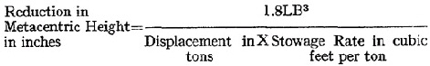
 in the case of wood shores or
 in the case of steel shores
 —
—  in the case of wood shores or the expression
  in the case of steel shores where—